38C - 2 ANTI-LOCK BRAKING SYSTEM Fault finding - Introduction 38C V2 MR-387-X77-38C050$062.mif 138C BOSCH 8.1 ESP Vdiag No.: 16 ANTI-LOCK BRAKING SYSTEM Fault finding - Introduction 1. SCOPE OF THIS DOCUMENT This document presents the fault finding procedure applicable to all computers with the following specifications: 2. PREREQUISITES FOR FAULT FINDING Documentation type Fault finding procedures (this manual): – Assisted fault finding (integrated into the diagnostic tool), Dialogys. Wiring Diagrams: – Visu-Schéma (CD-ROM), paper. Type of diagnostic tools – CLIP Special tooling required Vehicle(s): Modus Function concerned: BOSCH ESP 8.1 Name of computer: ESP 8.1 Program No.: VDIAG No: 16 Special tooling required Multimeter MR-387-X77-38C050$062.mif
38C - 3 ANTI-LOCK BRAKING SYSTEM Fault finding - Introduction 38C V2 MR-387-X77-38C050$062.mif BOSCH 8.1 ESP Vdiag No.: 16 3. RECAP Procedure To run fault finding on the vehicle computers, switch on the ignition. Faults Faults are declared as either present or stored (depending on whether they appeared in a certain context and have disappeared since, or whether they remain present but have not been diagnosed within the current context). The present or stored status of faults should be taken into consideration when the diagnostic tool is switched on after the + after ignition feed (without any system components being active). For a present fault, apply the procedure described in the Interpretation of faults section. For a stored fault , note the faults displayed and apply the instructions in the Notes section. If the fault is confirmed when the instructions in the Notes section are applied, the fault is present. Deal with the fault If the fault is not confirmed, check: – the electrical lines which correspond to the fault, – the connectors for these lines (for oxidation, bent pins, etc.), – the resistance of the component detected as faulty, – the condition of the wires (melted or split insulation, wear). Conformity check The aim of the conformity check is to check statuses and parameters that do not produce a fault display on the diagnostic tool when they are inconsistent. Therefore, this stage is used to: – carry out fault finding on faults that do not have a fault display, and which may correspond to a customer complaint. – check that the system is operating correctly and that there is no risk of a fault recurring after repairs. This section gives the fault finding procedures for statuses and parameters and the conditions for checking them. If a status is not behaving normally or a parameter is outside the permitted tolerance values, consult the corresponding fault finding page. Customer complaints - Fault finding chart If the test with the diagnostic tool is OK but the customer complaint is still present, the fault should be processed by customer complaint. A summary of the overall procedure to follow is provided on the following page in the form of a flow chart.
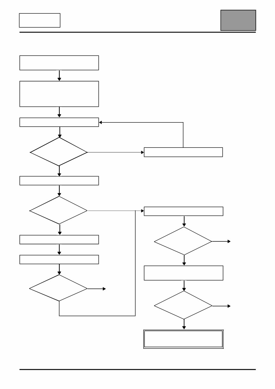
38C - 4 ANTI-LOCK BRAKING SYSTEM Fault finding - Introduction 38C V2 MR-387-X77-38C050$062.mif BOSCH 8.1 ESP Vdiag No.: 16 4. FAULT FINDING PROCEDURE Check the battery charge and the condition of the fuses Print the system fault finding log (available on CLIP and in the Workshop Repair Manual or Technical Note) Connect CLIP no Dialogue with computer? yes Read the faults no Faults present yes Deal with present faults Deal with stored faults no The cause is still present Fault solved yes Refer to ALP No. 1 Conformity check no The cause is still present Fault solved Use Fault Finding Charts (ALPs) no The cause is still present Fault solved Contact the Techline with the completed fault finding log
38C - 5 ANTI-LOCK BRAKING SYSTEM Fault finding - Introduction 38C V2 MR-387-X77-38C050$062.mif BOSCH 8.1 ESP Vdiag No.: 16 4. FAULT FINDING PROCEDURE (continued) Wiring check Fault finding problems Disconnecting the connectors and/or manipulating the wiring harness may temporarily remove the cause of a fault. Electrical measurements of voltage, resistance and insulation are generally correct, especially if the fault is not present when the analysis is made (stored fault). Visual inspection Look for damage under the bonnet and in the passenger compartment. Carefully check the fuses, insulators and wiring harness routing. Look for signs of oxidation. Tactile inspection While manipulating the wiring harness, use the diagnostic tool to note any change in fault status from stored to present. Make sure that the connectors are properly locked. Apply light pressure to the connectors. Twist the wiring harness. If there is a change in status, try to locate the source of the fault. Inspection of each component Disconnect the connectors and check the appearance of the clips and tabs, as well as their crimping (no crimping on the insulating section). Make sure that the clips and tabs are properly locked in the sockets. Make sure that no clips or tabs have been dislodged during connection. Check the clip contact pressure using an appropriate model of tab. Resistance check Check the continuity of entire lines, then section by section. Look for a short circuit to earth, to + 12 V or to another wire. If a fault is detected, repair or replace the wiring harness.
Introducing the 2005 Renault Modus Service and Repair Manual. This comprehensive manual is a must-have for all owners and enthusiasts of the Renault Modus model from the year 2005.
The 2005 Renault Modus Service and Repair Manual provides detailed step-by-step instructions, diagrams, and illustrations to help you accurately diagnose, service, and repair your vehicle. Whether you're a professional mechanic or a DIY enthusiast, this manual is designed to assist you in maintaining your Modus in top condition.
Key features of the 2005 Renault Modus Service and Repair Manual include:
Diagnostic procedures to identify and solve common problems
Detailed instructions for routine maintenance tasks
Comprehensive coverage of engine, transmission, suspension, and electrical systems
Exploded diagrams and illustrations for easy understanding
Step-by-step repair procedures for all components
Wiring diagrams for efficient electrical troubleshooting
Specifications and torque values for every part
Models covered:
Renault Modus 2005 1.2L
Renault Modus 2005 1.4L
Renault Modus 2005 1.5L
Renault Modus 2005 1.6L
With the 2005 Renault Modus Service and Repair Manual, you can confidently tackle any repairs or maintenance tasks on your Modus. Don't let car troubles hold you back, get your copy today and ensure the longevity and performance of your vehicle.