

Porsche 928 S S4 GT GTS Workshop Manual
What's Included?
Fast Download Speeds
Offline Viewing
Access Contents & Bookmarks
Full Search Facility
Print one or all pages of your manual
Wiring 97
Current Flow Diagram,Type 928 USA,
Symbols and Explanation
I
l
Current Flow Diagram
97-l
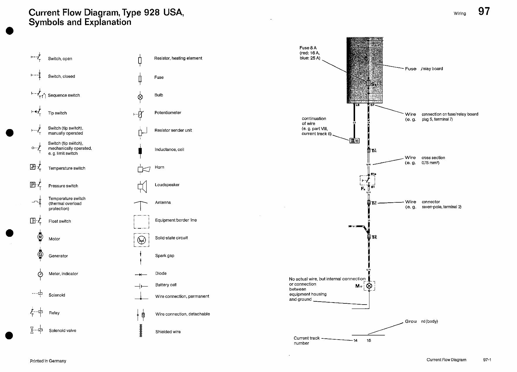
Current Flow Diagram,Type 928 USA,
Symbols and Explanation
Wiring 97
Fuse 8 A
(red: 16 A,
blue: 25 A) _
I
t
i---
T
Switch, open
0
Resistor, heating element
- Fuse Irelay board
Switch, closed
0
Fuse
C-
$
TfT Sequence switch
Q
Bulb
t-4
t
T
Tip switch
t-
Q
Potentiometer
continuation
I I!!
of wire
I Y
y Wire connection on fuse/relay board
(e. g. plug S, terminal 7)
i
l---
Switch (tip switch),
T manually operated
t
Switch (tip switch),
Q--
T
mechanically operated,
e. g. limit switch
P
Resistor sender unit
(e. 9. part VIII,
current track 6)
i
Inductance, coil
Et4 Temperature switch
N
Horn
B{ Pressure switch
Kl
Loudspeaker
t
Tz - wire Connector
(e. g. seven-pole, terminal 2)
Temperature switch
(thermal overload
protection)
m-4
Float switch
Motor
Antenna
r'-'-':
I ! Equipment border line
I
L.-.-. j
i-.-.-.-l
Solid-state circuit
No actual wire, but internal connection
or connection
between
equipment housing
and ground w
Generator
t
Spark gap
t
Meter, indicator 0 Diode
-I+
Battery cell
Wire connection, permanent
---
+
Solenoid
Relay
Wire connection, detachable
I I
I I
I I I
Shielded wire x+
--_
Solenoid valve
Current track -
number
,4 ,5
Printed in Gerrnany Current Flow Diagram
97-l
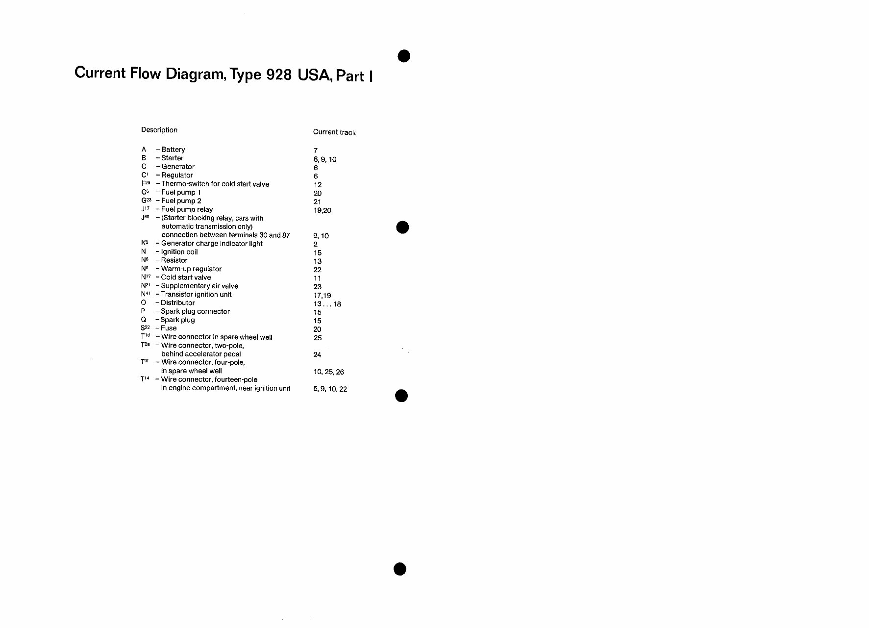
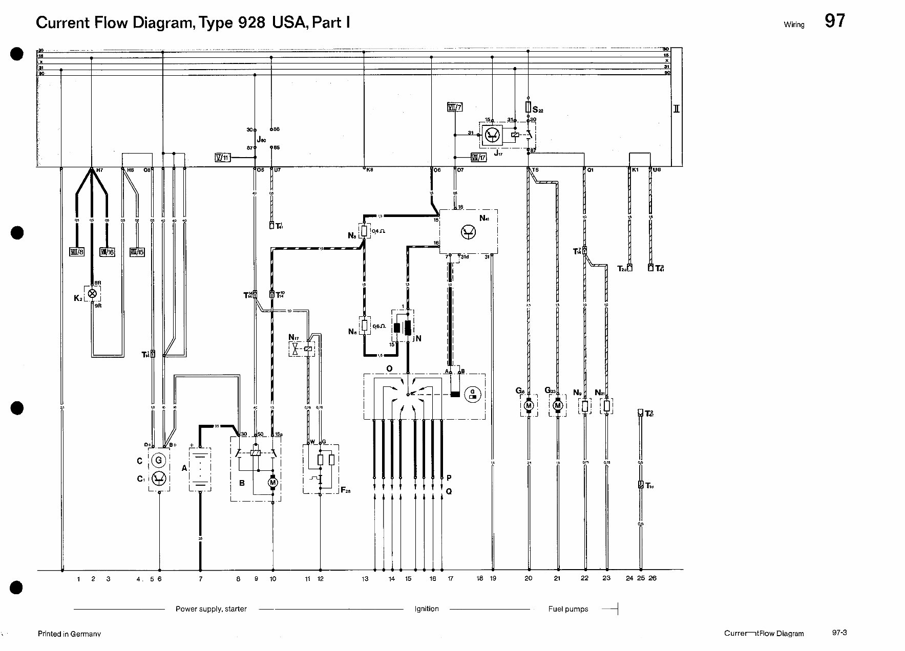
Current Flow Diagram, Type 928 USA, Part I
Description
A - Battery
B - Starter
C - Generator
C’ -Regulator
F*6 - Thermo-switch for cold start valve
G” -Fuel pump 1
G23 -Fuel pump 2
J’7 - Fuel pump relay
J@J - (Starter blocking relay, cars with
automatic transmission only)
connection between terminals 30 and 87
K* - Generator charge indicator light
N - Ignition coil
NC - Resistor
Ng -Warm-up regulator
N’7 - Cold start valve
N*’ -Supplementary air valve
N4’ -Transistor ignition unit
0 - Distributor
P - Spark plug connector
Q -Spark plug
S*2 -Fuse
Tld -Wire connector in spare wheel well
T2a - Wire connector, two-pole,
behind accelerator pedal
T4’ - Wire connector, four-pole,
in spare wheel well
T14 - Wire connector, fourteen-pole
in engine compartment, near ignition unit
Current track
7
8,9, 10
6
6
12
20
21
19,20
9, 10
2
15
13
22
11
23
17,19
13... 18
15
15
20
25
24
10,25,26
5,9,10,22
Wiring 97
Current Flow Diagram, Type 928 USA, Part I
Current Flow Diagram 97-3
Current Flow Diagram, Type 928 USA, Part I
Wiring 97
L- ._.-
7?--f31d 3
1
1 r-I
, I
j”i
I1
II
s 22
s
I
I
i
rs
1
T,:
*
I
Td
01
r
K2i
I.-
Tl!i
L
a
I--
-
-
1
/I
!,
i J
i.
N17
r.-
I
B
i.-
l====
a
v
,‘T
b j
r
0f f
r- -7
‘I
; F
I
i !I
_i 1
i i ’
G6
l-
i (
i
GZ
II L
j i.
-.-_-. j
P
D.
I
A
-
-_ .
!
35
5
I
12 3 4. 56 7 8 9 10 11 12 13 14 15 16 17 20 2-l 22 23 24 25 26
‘v Power supply, starter ~
Ignition Fuel pumps
+
Printed in Germanv
Current Flow Diagram
97-3
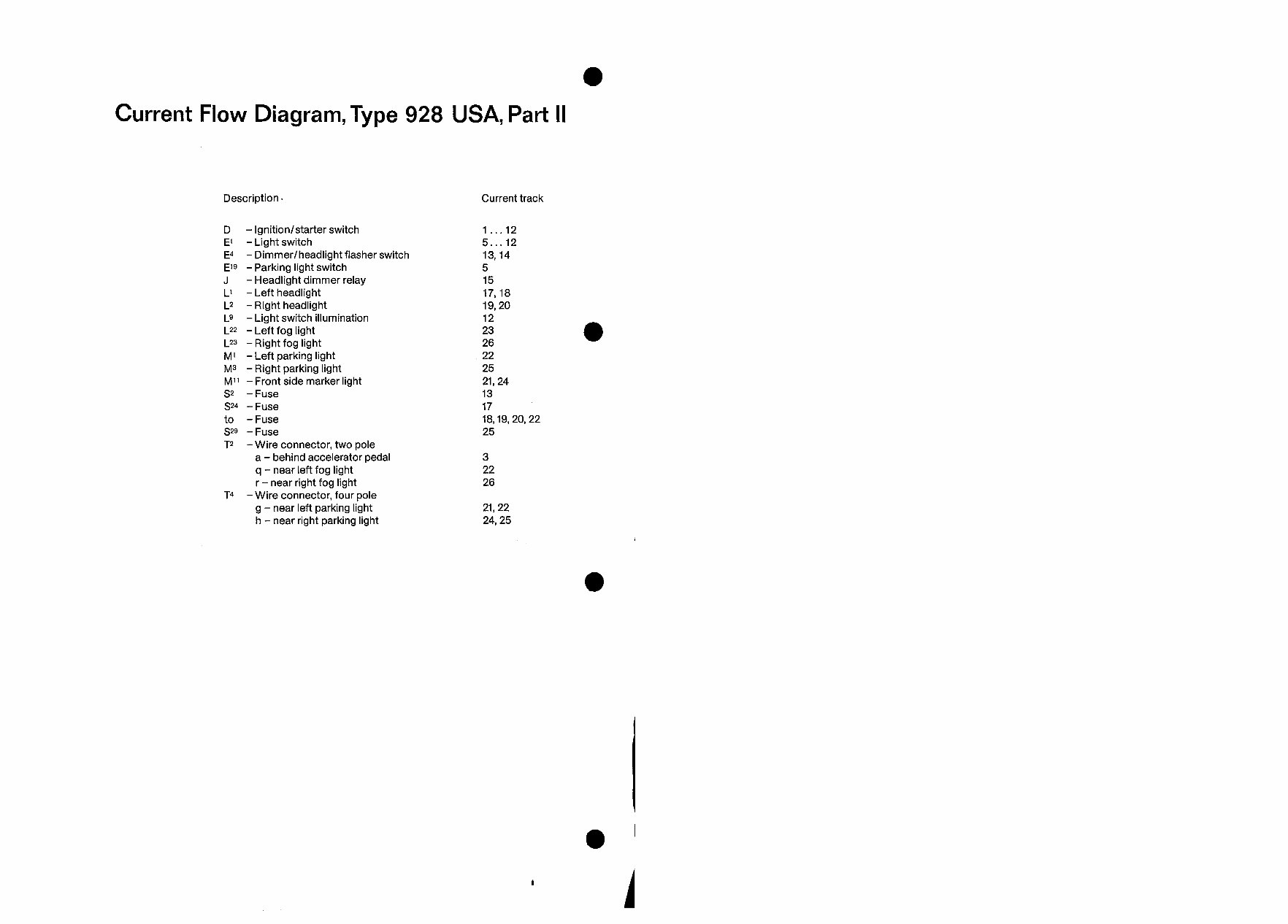
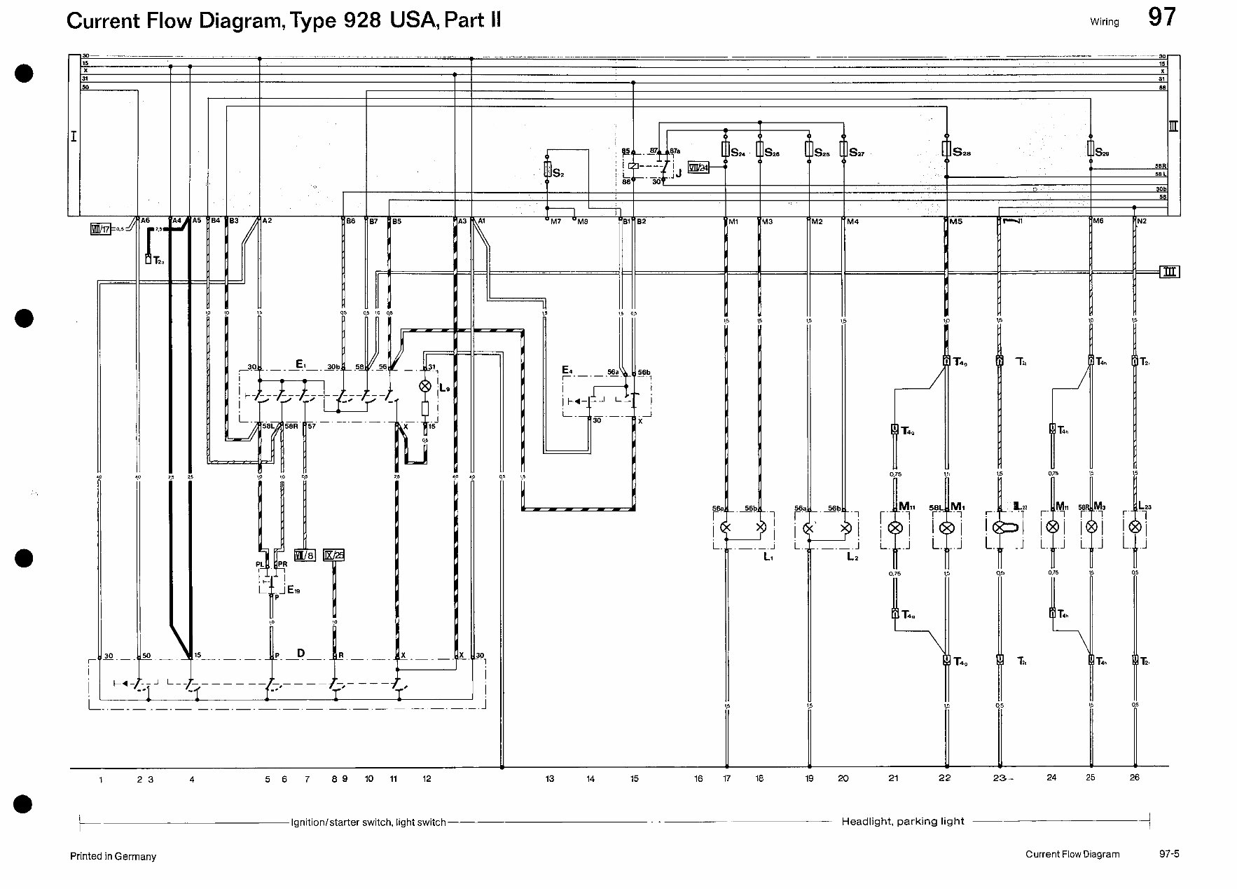
Current Flow Diagram, Type 928 USA, Part II
Description. Current track
D - Ignition/starter switch
E’ - Light switch
E4 - Dimmer/headlight flasher switch
El9 - Parking light switch
J - Headlight dimmer relay
L’ - Left headlight
L* - Right headlight
L9 - Light switch illumination
L** - Left fog light
L*3 -Right fog light
M’ -Left parking light
M3 - Right parking light
Ml’ - Front side marker light
s* - Fuse
S*4 -Fuse
to - Fuse
S*9 -Fuse
T* -Wire connector, two pole
a - behind accelerator pedal
q - near left fog light
r - near right fog light
T4 -Wire connector, four pole
g - near left parking light
h - near right parking light
1 . . . 12
5 12
13;;4
5
15
17,18
19,20
12
23
26
22
25
21,24
13
17
18,19,20,22
25
3
22
26
21,22
24,25
Wiring 97
Current Flow Diagram, Type 928 USA, Part II
Current Flow Diagram
97-5
Current Flow Diagram, Type 928 USA, Part II
Wiring 97
m
S25 s27
jkza
12 “M4 SM5 ;I-41
I
I
I
I
=m
1.5
ma2
!-’ - ‘1
1 i
t
i. -j
Q5
-Lo
I,5 0.5
i-L
E4 66a
r’-‘-‘--
ssb
1
ik+---l L- i
i-.
1
-.-.
;
i
30 x
T 4n T2r
5
9
!
‘i
i
j i
t
r 4n T&
w
1
r
T4h
0.75
r’ Pq p!
i
1
i ii
i. .j i.
0.75
L
T4n
1
..6br-.,
!
.-.-.
Li
I
I
I
I
I
I
I
I
‘P
H
L
Y------A 56
r
.-.--.-.-. .-.--.-.-.
t.0 t.0 1.00,” 1.00,” 2.5 2.5
i”
i 1
i.
i (
i
1 23 4 5 6 7 89 10 11 12 13 14 15 16 17 18 19 20 21 22 23 -* 24 25 26
Ignition/starter switch, light switch--
Headlight, parking light ~
Printed in Germany
Current Flow Diagram 97-5
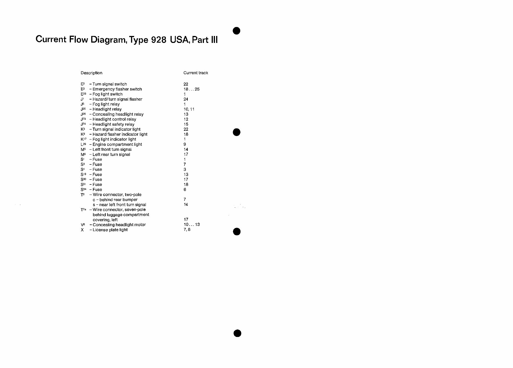
Current Flow Diagram, Type 928 USA, Part III
Description
E* -Turn signal switch
E3 - Emergency flasher switch
E*3 -Fog light switch
J’ -Hazard/turn signal flasher
J5 - Fog light relay
J*5 - Headlight relay
J36 - Concealing headlight relay
J73 - Headlight control relay
J74 - Headlight safety relay
K5 -Turn signal indicator light
K6 - Hazard flasher indicator light
Kl7 -Fog light indicator light
L29 - Engine compartment light
M5 - Left front turn signal
M6 - Left rear turn signal
S’ - Fuse
s3 - Fuse
S4 - Fuse
519 -Fuse
S30 - Fuse
S3’ - Fuse
S34 - Fuse
T* - Wire connector, two-pole
c - behind rear bumper
s - near left front turn signal
77a -Wire connector, seven-pole
behind luggage compartment
covering, left
Vs - Concealing headlight motor
X - License plate light
Current track
22
lg...25
1
24
1
10,ll
13
12
15
22
18
1
9
14
17
1
7
3
13
17
18
6
7
14
17
lo... 13
7,8
Wiring 97
Current Flow Diagram, Type 928 USA, Part Ill
Current Flow Diagram
97-7
You're Reading a Preview
What's Included?
Fast Download Speeds
Offline Viewing
Access Contents & Bookmarks
Full Search Facility
Print one or all pages of your manual
$31.99
Viewed 82 Times Today


Secure transaction
What's Included?
Fast Download Speeds
Offline Viewing
Access Contents & Bookmarks
Full Search Facility
Print one or all pages of your manual
$31.99
The Porsche 928 S S4 GT GTS Workshop Manual is a comprehensive guide available in English. It comes in PDF format, making it accessible to both professional mechanics and DIY enthusiasts. This manual provides detailed technical information essential for car repair, maintenance, and troubleshooting.


