Workshop manual DR. ING. h. c. F. PORSCHE KG STUTTGART - ZU FFENHAUSEN
PORSCHE WORKSHOP MANUAL 911 - FROM MODEL 1972 ON This publication contains the essential removal, installation and adjustment procedures for the Porsche 911 vehicles sold in the USA and Canada. Components and procedures described in this manual are identical for all types unless differences are pointed out in the text. It is assumed that the reader is familiar with basic automotive repair procedures. Special tools required in performing certain service operations are identified in the manual and recommended for use. Use of tools or procedures other than those recommended in this repair manual may be detrimental to the vehicle's safe operation as well as the safety of the person servicing the vehicle. The Workshop Manual 911 - from model 1972 on - is subdivided into 10 Assembly Groups, delive- red in supplements to volume I and 11. Survey of the individual Assembly Groups: Engine and Clutch Fuel System Transmission Front Axle Rear Axle Brakes, Wheels, Tires Code No. 1 Code No. 2 Code No. 3 Code No. 4 Code No. 5 Code No. 6 Pedal Controls and Manual Controls Code No. 7 Maintenance Jobs, Technical Data Code No.. 0 Body Code No. 8 Electrical System Code No. 9 For identification of the volumes, the back of the folders is provided with a transparent pocket at the top for insertion of the pertinent type. To find the individual repair steps quickly, each Assembly Group of this Workshop Manual is sub- divided into "Main Groups", "Chapters" and "Sections" and provided with a very detailed list of contents; refer to example on next page. Technical Information sheets should be filed at the beginning of their respective groups. The contents of the Technical Informations will be incorporated into the Workshop Manual at suitable intervals. The List of Contents will be edited whenever extensions and supplements are published. - XXXII, 1974 USA /CAN
Motor und Kupplung Engine and Clutch Moteur et Accouplement Motore e Frizione
ENGINE 911 1 CONTENTS 0 - INFORMATION, DESCRIPTION, TECHNICAL DATA 0.1 Description Engine changes - 1972 model Oil tank changes - 1972 model Oil cooler system and oil circuit schematic Oil cooler.schematic - 1973 model Oil cooler schematic with cooling coil - 1974 model Engine, front view cross section Engine, ' side view cross section Specifications for 2.7 liter - engine where differ 2.4 liter - engine Engine changes - 1974 model Cross section of engine with emission control equipment Layout of exhaust gas recirculation system Engine cross section with emission control - 1978/1979 models Emission control layout - 1980 model 0.2 Technical data General data Power performance curves Technical data, Type 911 T - Continuous Injection System (CIS) Technical data, Type 911/S/Carrera - 1974 model Full - power performance - 1974 model Technical data, Type 911 S and Carrera - 1975 model Engine tightening data Technical data, Type 911 - 1976 model Technical data, Type 911 S - 1977 model Technical data, Type 911 SC - 1978 model Technical data, Type 911 SC - 1980 model Technical Data, Type 911 SC - from 1981 Models COOLING SYSTEM, EXHAUST SYSTEM, EMISSION CONTROL 2.1 Cooling system Fan drive belt, replacing/adjusting
ENGINE 2.2 Exhaust system and heating Exhaust system and heater blower, removing and installing Exhaust system - 1978 model 2.3 Emission control Air injection components, removing and installing Air pump belt, tensioning Reactors and EGR equipment, removing and installing Exhaust gas recirculation system Reactor, checking for 1e:aks Exhaust gas recirculation system, checking Air injection system, checking 3 - OIL CIRCULATION 3.1 O'il circulation , Oil tank, removing and installing Oil tank, removing and installing - 1973 model Auxiliary pressure relief valve, removing and installing Auxiliary pressure relief valve, disassembling and assembling Oil cooler coil, removing and installing Oil cooler, removing and installing 3.2 Oil tank, removing and installing - 1974 model 3.3 Pressure relief valve cooling coil, removing and installing - 1974 model; 3.4 Pressure relief valve, disassembling and assembling - 1974 model 3.5 Oil cooler coil, removing and installing - 1974 model Cooling coil oil lines, service installing - 1974 model Replacing oil lines to front oil cooler or to cooling coil Oil cooler, removing/installing Auxiliary pressure relief/safety valves 5 - CAMSHAFT HOUSING AND CYLINDER HEAD j 5.1 Camshaft housing Injection tube in camshaft housing, removing and installing Chain tensioner, overhauling Sealing cylinder head/camshaft housing mating surfaces
ENGINE 911 1 5.2 Cylinder head Valve springs, installed length Adjusting timing 6 - CYLINDERS AND PISTONS 6.1 Cylinders and pistons Piston changes - 1972 model Piston and cylinder dimensions - 1972 model Piston and cylinder dimensions - 1973 model Piston and cylinder dimensions - 1974 model " LS " cylinders and pistons, installation instructions Pistons and cylinders, measuring Piston and cylinder sizes, 911 SC - 1978 model Piston weight classes - 911 SC from 1981 models 7 - CRANKCASE AND CRANKSHAFT 7.1 Crankcase and crankshaft Crankcase, measuring and reconditioning 'Modified flywheel installation - 1978 model Flywheel with pilot bearing - 1980 model Oil filter screen and suction plate, removing/installing Crankshaft Crankshaft changes - 1972 model Crankshaft dimensions Connecting rod changes - 1972 model Connecting rod weight groups Connecting rod weight groups - 1978 model Pistons for injection engines Modified crankshaft drive - 1978 model Crankshaft specifications, standard and undersize - 1978 model
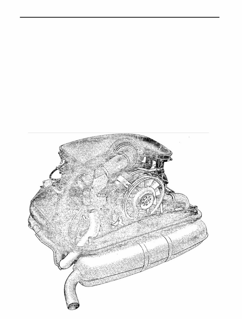
Engine Description 911 1 ENGINE CHANGES - B E G I N N I N G WITH 1972 MODELS General Information Beginning with 1972 models, Type 911 engines have a cubic displacement of 2.4 liters (2341 c/142.8 cu. in. )
911 Engine Description Individual changes and changed service operations are described on the pages that follow. Summary of Changes: 1. Technical Data 2. Crankcase 3. Crankshaft 4. Connecting rods and bearings 5. Pistons 6. Location of oil tank and oil lines 7. Clutch pressure plate, throwout bearing, and clutch disc 8. Ignition - see Group 9 (Electrical System) 9. Fuel system - see Group 2
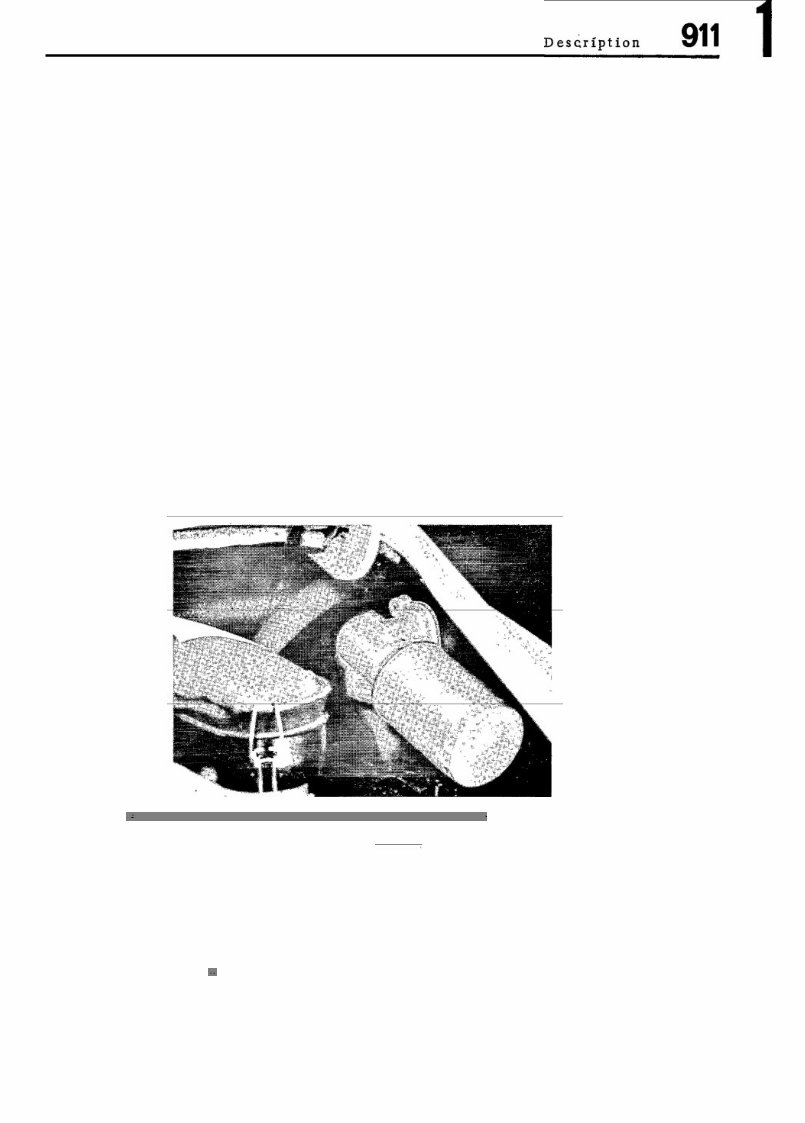
OIL TANK CHANGES - BEGINNING WITH 1972 MODELS General Information Beginning with 1972 models, the oil tank is located in right rear wheelhousing in front of the rear axle. The oil filler neck is now accessible from the outside. It is located under a hinged lid in the right rear fender. The oil filter housing is separated from the tank and mounted on the right engine compartment wall. The auxiliary oil cooler under the right front fender continues to be standard equipment in Type 911s vehicles.
The PORSCHE 911 CARRERA 1975 Service and Repair Manual is a comprehensive resource for all your maintenance and repair needs. Whether you own a classic 1975 Porsche 911 Carrera or you're a mechanic looking for detailed information, this manual is the perfect guide to keep your vehicle running smoothly.
The manual covers various models of the Porsche 911 Carrera released in 1975, including:
Porsche 911 Carrera Coupe
Porsche 911 Carrera Targa
Porsche 911 Carrera Cabriolet
Inside, you'll find step-by-step instructions, diagrams, and illustrations to assist you in successfully completing a range of repairs and services. The manual covers everything from routine maintenance tasks to more complex engine repairs, electrical systems, transmission, suspension, and more.
With this service and repair manual, you'll have access to detailed specifications, torque values, and troubleshooting tips to help diagnose and fix any issues you may encounter. Whether you're a seasoned Porsche enthusiast or a beginner mechanic, this manual is a valuable resource to have in your collection.
Make sure your beloved Porsche 911 Carrera 1975 stays in top-notch condition with the PORSCHE 911 CARRERA 1975 Service and Repair Manual.