

2009-2010 Pontiac Vibe Service & Repair Manual
What's Included?
Fast Download Speeds
Offline Viewing
Access Contents & Bookmarks
Full Search Facility
Print one or all pages of your manual

2009 Pontiac Vibe - AWD | Vibe (VIN S) Service Manual | Brakes | Antilock Brake System | Specifications |
Document ID: 2033874
Fastener Tightening Specifications
Application
Specification
Metric English
Brake Pipe Fitting Nuts 15 N·m 11 lb ft
Brake Pressure Modulator Valve Assembly to Bracket Bolts 5.4 N·m 48 lb in
Brake Pressure Modulator Valve Bracket Attaching Bolts 19 N·m 14 lb ft
Brake Pressure Modulator Valve Bracket Attaching Nut 19 N·m 14 lb ft
Front Wheel Speed Sensor Bolt 8.5 N·m 75 lb in
Front Wheel Speed Sensor Pigtail Harness Lower Bolt 29 N·m 21 lb ft
Front Wheel Speed Sensor Pigtail Harness Upper Bolt 8 N·m 71 lb in
Rear Wheel Speed Sensor Bolt (AWD) 8.5 N·m 75 lb in
Rear Wheel Speed Sensor Pigtail Harness Bolts (AWD) 8 N·m 71 lb in
Rear Wheel Speed Sensor Pigtail Harness Nut (AWD) 5 N·m 44 lb in
Rear Wheel Speed Sensor Pigtail Harness Lower Bolt (FWD) 19 N·m 14 lb ft
Rear Wheel Speed Sensor Pigtail Harness Upper Bolt (FWD) 5 N·m 44 lb in
© 2010 General Motors Corporation. All rights reserved.
Page 1 of 1 Document ID: 2033874
4/16/2010 http://localhost:9001/si/showDoc.do?docSyskey=2033874&pubCellSyskey=940&pubObj...
2009 Pontiac Vibe - AWD | Vibe (VIN S) Service Manual | Brakes | Antilock Brake System | Repair Instructions |
Document ID: 2033543
Brake Pressure Modulator Valve Replacement
Removal Procedure
1. Remove the right front wheel and tire assembly. Refer to Tire and Wheel Removal and
Installation .
2. Remove the right engine undercover. Refer to Engine Splash Shield Replacement - Right
Side .
3. Remove the generator. Refer to Generator Replacement .
4. Remove the coolant surge tank. Refer to Radiator Surge Tank Replacement .
5. Remove the washer reservoir. Refer to Windshield Washer Solvent Container Replacement .
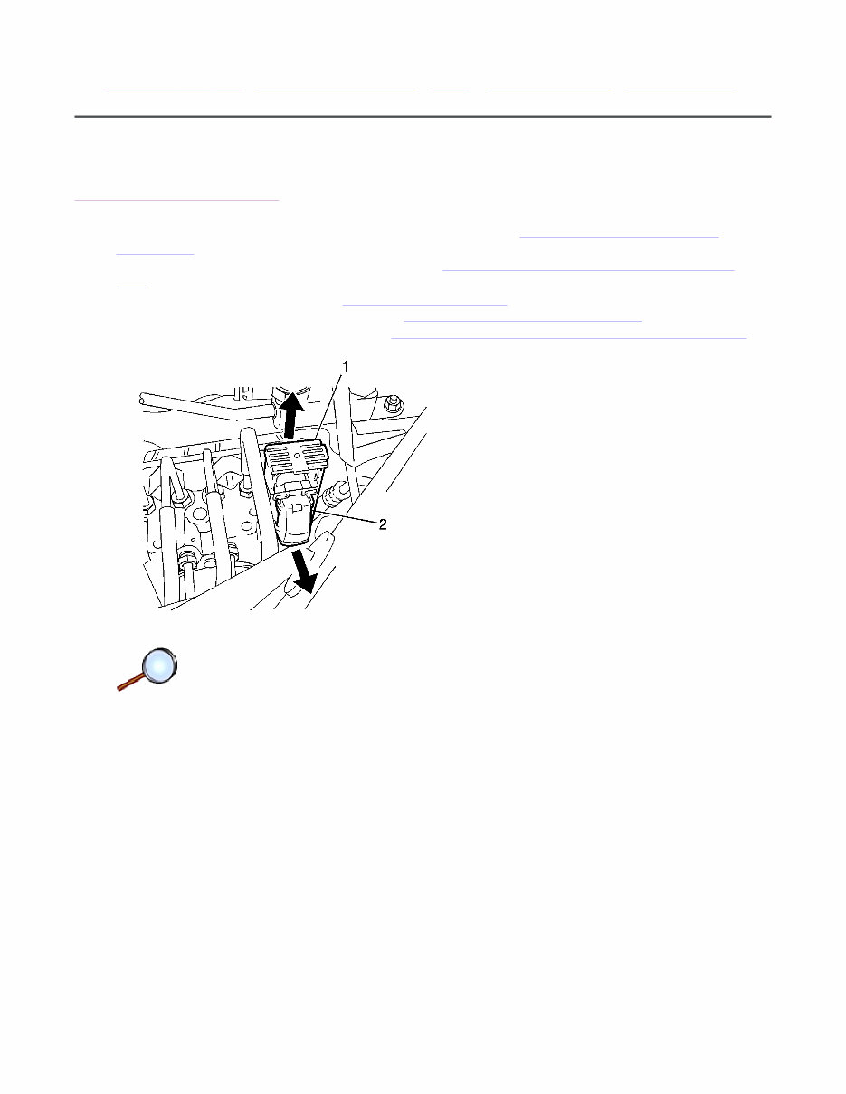
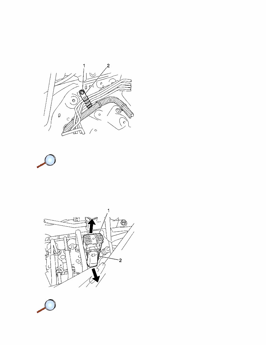
6. Release the electronic brake control module (EBCM) harness connector lock lever (1).
7. Disconnect the EBCM harness connector (2).
© 2010 General Motors Corporation. All rights reserved.
Page 1 of 7 Document ID: 2033543
4/16/2010 http://localhost:9001/si/showDoc.do?docSyskey=2033543&pubCellSyskey=1189&pubObj...
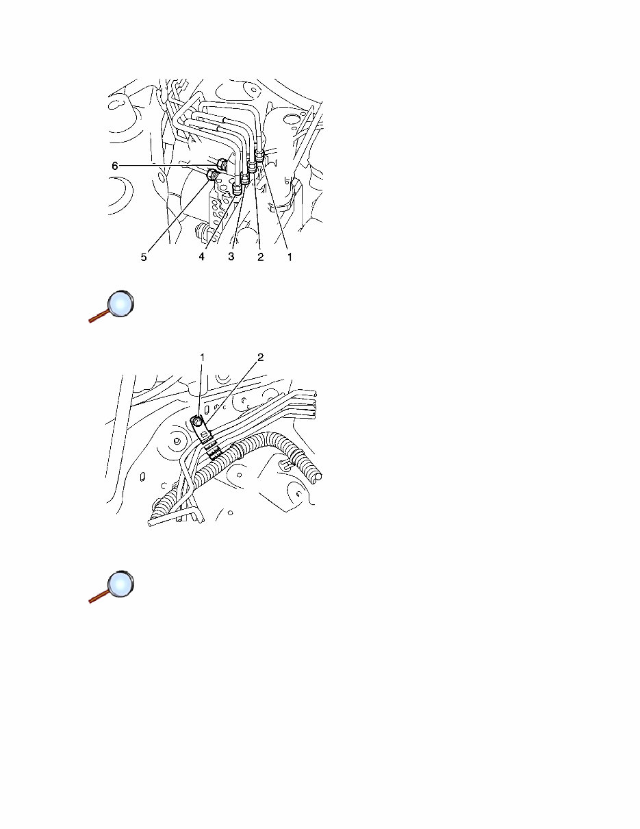
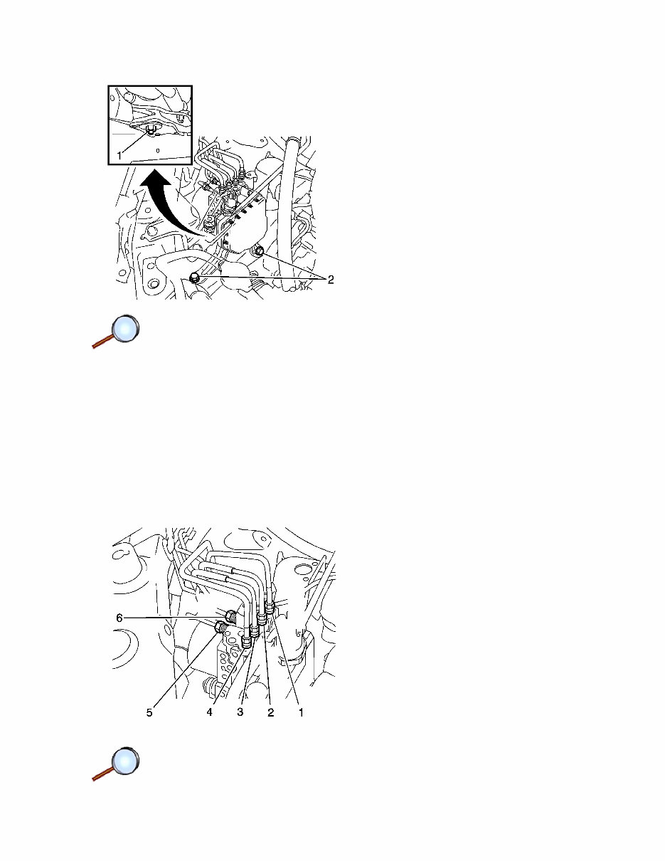
8. Mark the brake pipes (1-6) to aid in installation.
9. Remove the brake line clamp bolt (1) and clamp (2).
Page 2 of 7 Document ID: 2033543
4/16/2010 http://localhost:9001/si/showDoc.do?docSyskey=2033543&pubCellSyskey=1189&pubObj...
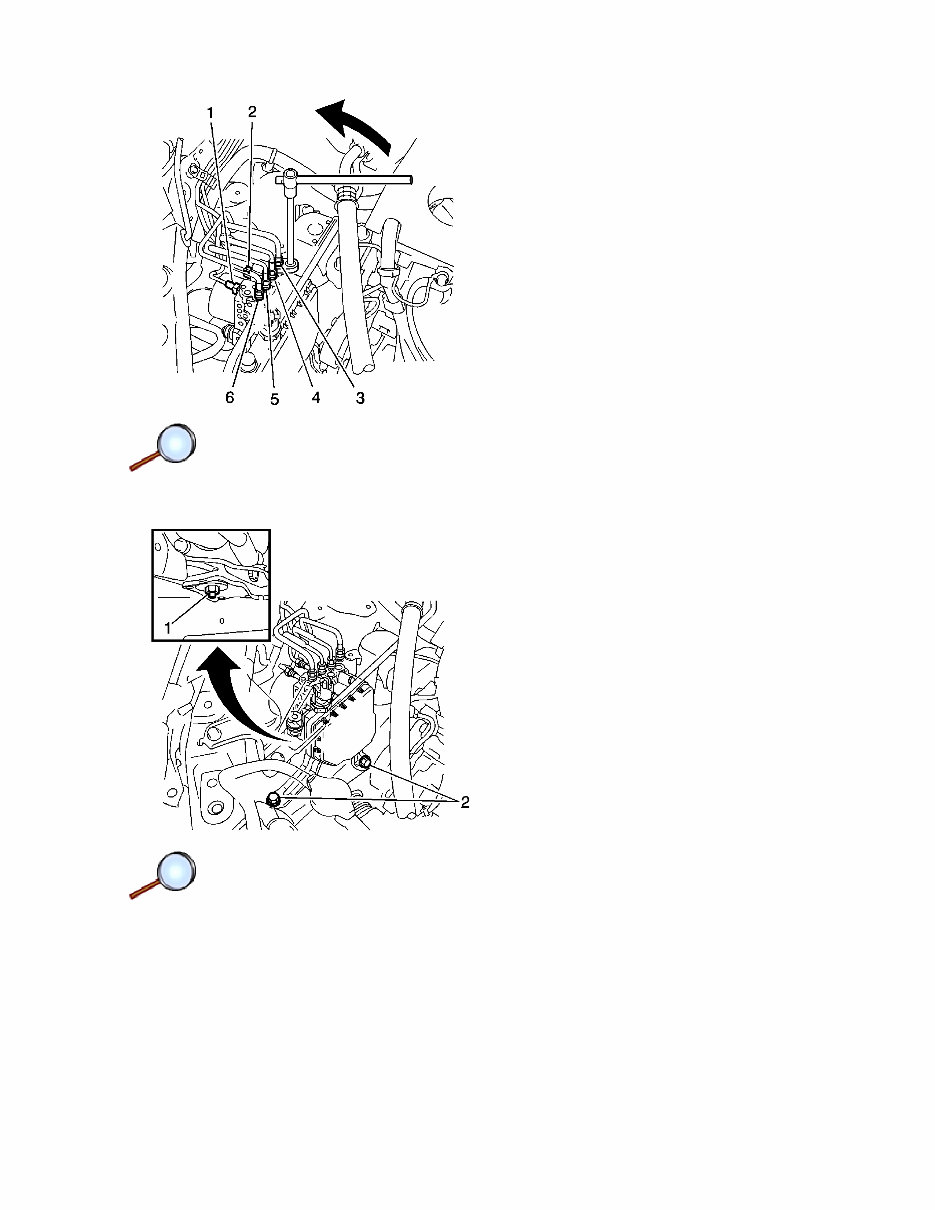
10. Remove the brake pipes (1-6) from the brake modulator assembly.
11. Plug the brake pipes in order to prevent loss or contamination of brake fluid.
12. Remove the 2 bolts (2) from the brake pressure modulator bracket (3).
13. Remove the nut (1) and the brake pressure modulator assembly and bracket.
Page 3 of 7 Document ID: 2033543
4/16/2010 http://localhost:9001/si/showDoc.do?docSyskey=2033543&pubCellSyskey=1189&pubObj...
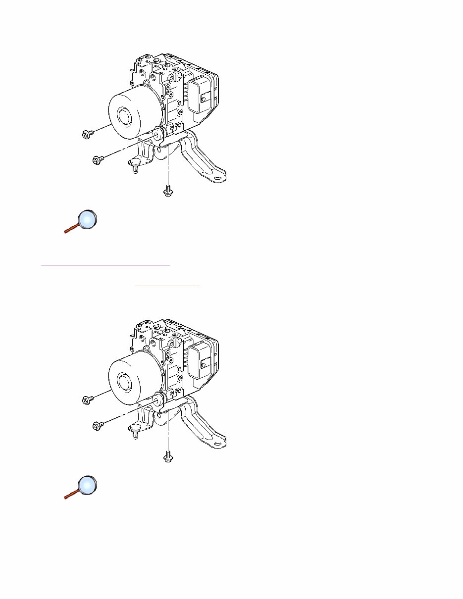
14. Remove the 3 bolts and the brake pressure modulator assembly from the bracket.
Installation Procedure
Caution: Refer to Fastener Caution in the Preface section.
1. Install the brake pressure modulator assembly to the bracket. Secure with the 3 bolts.
Tighten
Tighten the brake modulator assembly nuts to 5 N·m (48 lb in).
Page 4 of 7 Document ID: 2033543
4/16/2010 http://localhost:9001/si/showDoc.do?docSyskey=2033543&pubCellSyskey=1189&pubObj...
2. Install the 2 bolts (2) to the brake pressure modulator bracket (3).
Tighten
Tighten the brake modulator bracket bolts to 19 N·m (14 lb ft).
3. Install the brake pressure modulator assembly and bracket. Secure with the nut (1).
Tighten
Tighten the brake modulator bracket nut to 19 N·m (14 lb ft).
4. Remove the plugs from the brake pipes and connect the brake pipes to the brake modulator
Page 5 of 7 Document ID: 2033543
4/16/2010 http://localhost:9001/si/showDoc.do?docSyskey=2033543&pubCellSyskey=1189&pubObj...
assembly (1).
Tighten
Tighten the brake pipe fittings nuts to 15 N·m (11 lb ft).
5. Install the brake line clamp (2) and secure with bolt (1).
Tighten
Tighten the brake line clamp bolt to 5 N·m (48 lb in).
6. Connect the EBCM electrical connector (2).
Page 6 of 7 Document ID: 2033543
4/16/2010 http://localhost:9001/si/showDoc.do?docSyskey=2033543&pubCellSyskey=1189&pubObj...

7. Secure the EBCM electrical connector lock lever (1).
8. Install the washer reservoir. Refer to Windshield Washer Solvent Container Replacement .
9. Install the coolant surge tank. Refer to Radiator Surge Tank Replacement .
10. Install the generator. Refer to Generator Replacement .
11. Install the right engine undercover. Refer to Engine Splash Shield Replacement - Right Side .
12. Install the right front wheel and tire assembly. Refer to Tire and Wheel Removal and
Installation .
13. Bleed the brake system. Refer to Hydraulic Brake System Bleeding .
14. Using the scan tool, perform the yaw rate sensor zero point calibration under the special
functions menu.
15. Perform the Diagnostic System Check - Vehicle .
16. Refer to Control Module References for programming and setup information.
Page 7 of 7 Document ID: 2033543
4/16/2010 http://localhost:9001/si/showDoc.do?docSyskey=2033543&pubCellSyskey=1189&pubObj...
2009 Pontiac Vibe - AWD | Vibe (VIN S) Service Manual | Brakes | Antilock Brake System | Repair Instructions |
Document ID: 2033533
Front Wheel Speed Sensor Replacement
Removal Procedure
1. Remove the wheelhousing. Refer to Wheelhouse Panel Replacement .
Note: The wheel speed sensor is serviceable only as an assembly. Do NOT attempt to service
the sensor harness pigtail.
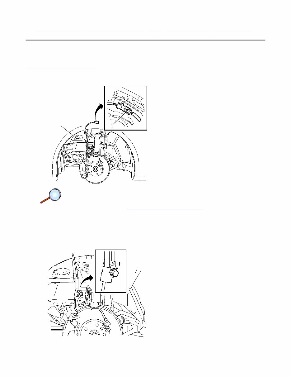
2. Disconnect the wheel speed sensor electrical connector (1).
© 2010 General Motors Corporation. All rights reserved.
Page 1 of 6 Document ID: 2033533
4/16/2010 http://localhost:9001/si/showDoc.do?docSyskey=2033533&pubCellSyskey=1415&pubObj...
3. Remove the bolt (1) retaining the wheel speed sensor pigtail harness.
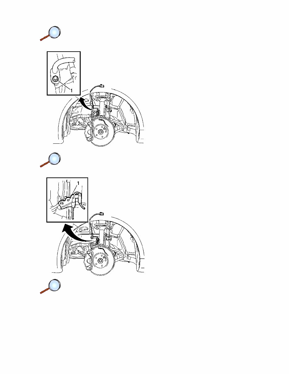
4. Remove the bolt (1) and separate the brake hose.
5. Remove the bolt (1) and the sensor clamp from the strut.
Page 2 of 6 Document ID: 2033533
4/16/2010 http://localhost:9001/si/showDoc.do?docSyskey=2033533&pubCellSyskey=1415&pubObj...
You're Reading a Preview
What's Included?
Fast Download Speeds
Offline Viewing
Access Contents & Bookmarks
Full Search Facility
Print one or all pages of your manual
$39.99
Viewed 39 Times Today


Secure transaction
What's Included?
Fast Download Speeds
Offline Viewing
Access Contents & Bookmarks
Full Search Facility
Print one or all pages of your manual
$39.99
The 2009-2010 Pontiac Vibe OEM Service & Repair Manual is a comprehensive guide providing detailed instructions and information for servicing and repairing Pontiac Vibe models from the years 2009 to 2010. This manual is an essential resource designed for both professional mechanics and DIY enthusiasts, offering the confidence to handle any maintenance or repair task.
Key features of the 2009-2010 Pontiac Vibe OEM Service & Repair Manual include:
- Step-by-step instructions: Easy-to-follow, step-by-step directions for a variety of repairs and maintenance procedures ensure that tasks are completed effectively and efficiently.
- Detailed diagrams and illustrations: Filled with clear diagrams, illustrations, and schematics to provide visual guidance and support throughout the repair process.
- Comprehensive coverage: Extensive information covering all aspects of servicing and repairing Pontiac Vibe models from 2009 to 2010, including the engine, transmission, electrical system, suspension, brakes, and more.
- Troubleshooting guides: Helpful troubleshooting guides to accurately diagnose and resolve any issues or problems encountered with your Pontiac Vibe.
- Maintenance schedules: Recommended maintenance schedules and procedures to keep your Pontiac Vibe operating at its best for years to come.
With the 2009-2010 Pontiac Vibe OEM Service & Repair Manual at your disposal, you can save time and money by performing repairs and maintenance on your own. This manual is a must-have for anyone owning or working on a Pontiac Vibe from 2009 to 2010.


