A/C COMPRESSOR CLUTCH CONTROLS A/C COMPRESSOR CLUTCH CONTROLS General Motors Corp. MODEL IDENTIFICATION BODY CODE DESIGNATIONS DESCRIPTION & OPERATION To improve idle quality and Wide Open Throttle (WOT) performance, and for system protection, the A/C compressor clutch is controlled by the Powertrain Control Module (PCM). Refrigerant switches used are low pressure switch (front A/C option), high pressure cut-out switch (front and rear A/C options), and A/C pressure cycling switch (rear A/C option). Different pressure switches are used because vehicles are equipped with different A/C compressors depending on A/C option installed. The A/C compressor clutch relay is controlled by the PCM. This allows the PCM to raise idle speed before engaging compressor clutch, and disable compressor clutch during WOT or if coolant temperature becomes excessive. PCM inhibits A/C compressor clutch operation until engine speed is less than 4000 RPM for 3 seconds. PCM engages Torque Converter Clutch (TCC) at 2 different speeds depending on A/C system operation. When A/C is off, PCM will engage TCC at about 30 MPH. When A/C is on, PCM will engage TCC at about 35 MPH. TROUBLE SHOOTING Trouble shoot A/C compressor clutch control using appropriate schematic and diagnostic charts. See TROUBLE SHOOTING CHART DIRECTORY. "U" Series, see A/C COMPRESSOR CLUTCH RELAY LOCATION table for A/C compressor clutch relay location. RELAY LOCATION Model (1) Series Designation Lumina Minivan, Silhouette & Trans Sport "U" (1) Series codes determined by fifth character of VIN code NOTE: The "U" Series FWD vans have PCM-controlled A/C compressor clutch circuits. NOTE: This article contains test charts which are part of General Motors Computerized Engine Controls. Only those charts required to test A/C compressor clutch control are included. Other diagnostic information may be referenced while performing A/C compressor clutch control diagnosis. For complete information on General Motors Computerized Engine Control systems, see the G-TESTS W/CODES article in the ENGINE PERFORMANCE section.
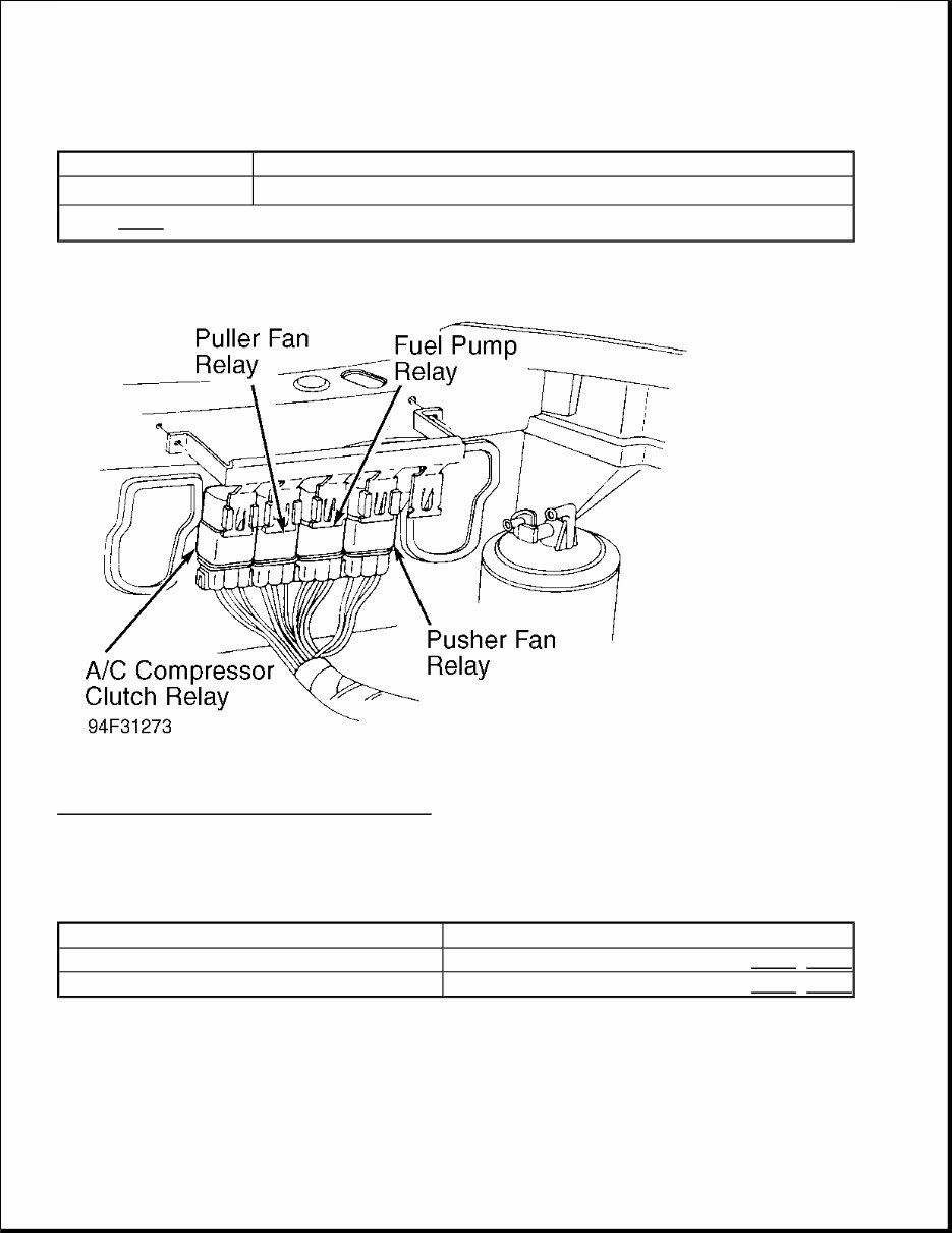
A/C COMPRESSOR CLUTCH RELAY LOCATION Fig. 1: Locating A/C Compressor Clutch Relay Courtesy of GENERAL MOTORS CORP. TROUBLE SHOOTING CHART DIRECTORY A/C COMPRESSOR CLUTCH CHART INDEX SCAN TESTER A variety of information is transmitted through Data Link Connector (DLC) terminal "E" or "M", depending on engine. This data is transmitted at a high frequency which requires a Tech 1 scan tester for interpretation. Several scan testers are available for diagnostic work. Scan testers other than Tech 1 scan tester will function Application Location "U" Series (1) On Bracket, Behind Right Headlight (1) See Fig. 1 . Application See Figure: 3.1L VIN D Fig. 2 -Fig. 5 3.8L VIN L Fig. 6 -Fig. 9
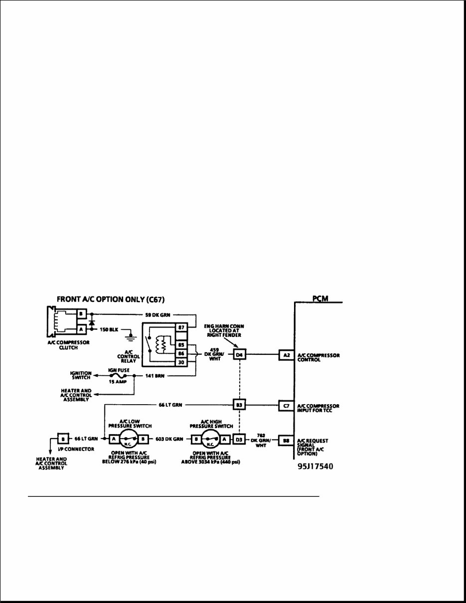
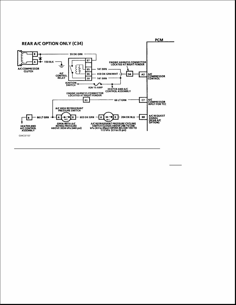
and provide information for diagnostic work; however, some charts will specify a Tech 1 scan tester. Failure to use a Tech 1 scan tester when specified may result in incorrect diagnosis of a system. TROUBLE SHOOTING CHARTS CHART C-10 - A/C COMPRESSOR CLUTCH CIRCUIT DIAGNOSIS 3.1L - VIN D Powertrain Control Module (PCM) delays A/C compressor clutch engagement about 8 seconds after engine is started. This delay allows Idle Air Control (IAC) motor to adjust engine RPM before A/C compressor clutch engages. PCM also disengages A/C compressor clutch during Wide Open Throttle (WOT) or if engine is overheating. A/C compressor clutch is energized when PCM grounds circuit No. 459. The low pressure switch will open if refrigerant pressure is less than 40 psi (2.8 kg/cm 2 ). The high pressure switch will open if refrigerant pressure is greater than about 440 psi (3.1 kg/cm 2 ). Vehicles equipped with a rear A/C option use a refrigerant pressure cycling switch instead of a low pressure switch. A/C refrigerant pressure cycling switch closes when refrigerant pressure is greater than 43-49 psi (3-3.4 kg/cm 2 ), and opens when refrigerant pressure is less than 18-22 psi (1.3-1.5.0 kg/cm 2 ). When refrigerant pressure exceeds about 200 psi (14 kg/cm 2 ), an A/C refrigerant fan request switch opens, turning fans on. Fig. 2: A/C Compressor Clutch Circuit Diagram (Front A/C) (3.1L VIN D) Courtesy of GENERAL MOTORS CORP.
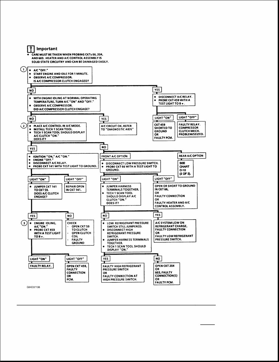
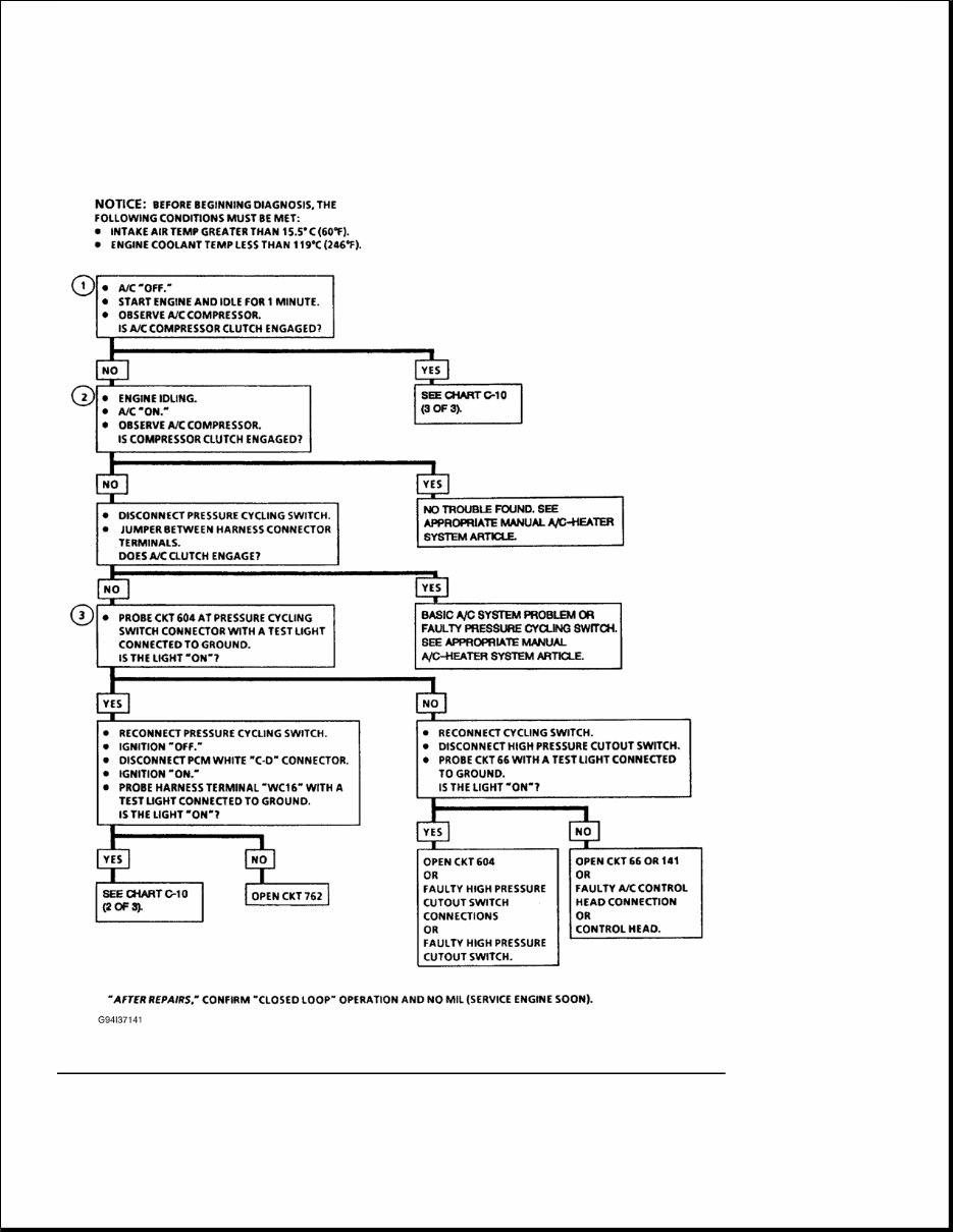
Fig. 3: A/C Compressor Clutch Circuit Diagram (Rear A/C) (3.1L VIN D) Courtesy of GENERAL MOTORS CORP. 1) PCM will only energize A/C compressor clutch relay when engine is running. This test determines whether relay or circuit No. 459 is faulty. 2) Determines if signal is reaching PCM on circuit No. 66 from A/C control panel. Signal should only be present when A/C mode or defrost mode is selected. 3) With engine idling and A/C on, PCM should ground circuit No. 459, causing test light to come on. NOTE: Test numbers refer to numbers on diagnostic chart. See Fig. 4
Fig. 4: A/C Compressor Clutch System Diagnosis, Flow Chart (1 Of 2) (3.1L - VIN D) Courtesy of GENERAL MOTORS CORP. NOTE: Test numbers refer to numbers on diagnostic chart. See Fig. 5
1) Determines if signal is reaching PCM on circuit No. 66 from A/C control panel. Signal should only be present when A/C mode or defrost mode is selected.
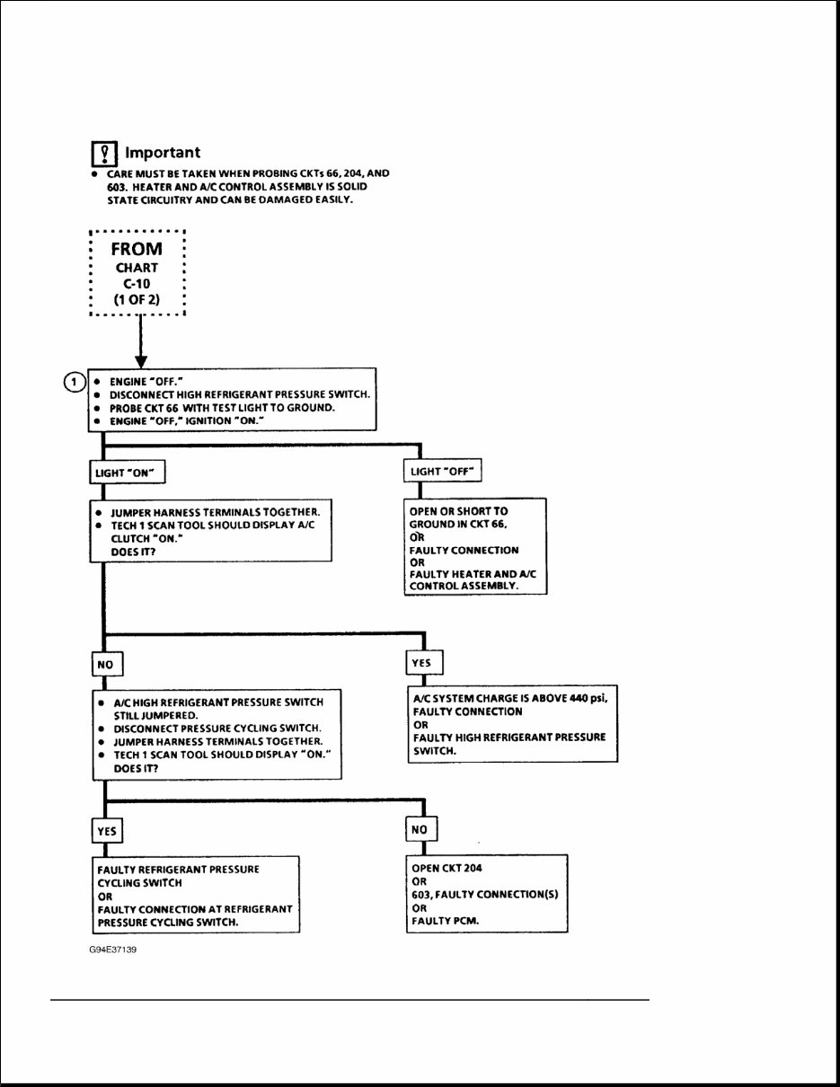
Fig. 5: A/C Compressor Clutch System Diagnosis, Flow Chart (2 Of 2) (3.1L - VIN D)
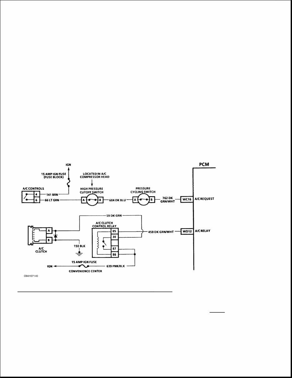
Courtesy of GENERAL MOTORS CORP. Diagnostic Aids If complaint is insufficient cooling, problem may be caused by inoperative cooling fan(s) or A/C refrigerant fan request switch. Engine cooling fan(s) should turn on when refrigerant pressure exceeds a predetermined value, opening switch and causing PCM to energize cooling fan relay(s). See appropriate C-12 chart in the ENGINE COOLING FANS article in the ENGINE COOLING section. If cooling fan operates correctly, problem is a basic A/C system problem. CHART C-10 - A/C COMPRESSOR CLUTCH CIRCUIT DIAGNOSIS 3.8L - VIN L Powertrain Control Module (PCM) delays A/C compressor clutch engagement momentarily after A/C is turned on. This delay allows Idle Air Control (IAC) motor to adjust engine RPM before A/C compressor clutch engages. PCM also disengages A/C compressor clutch during Wide Open Throttle (WOT). A/C compressor clutch is energized when PCM grounds circuit No. 459. PCM may engage A/C compressor clutch during engine cranking. Fig. 6: A/C Compressor Clutch Circuit Diagram (3.8L - VIN L) Courtesy of GENERAL MOTORS CORP. 1) A/C compressor clutch should not be engaged with engine running if an A/C mode is not selected at control head. 2) A/C compressor clutch should apply if conditions under NOTICE at top of chart are met. NOTE: Test numbers refer to numbers on diagnostic chart. See Fig. 7
3) Checks for an A/C request signal from control head to pressure cycling switch. Fig. 7: A/C Compressor Clutch System Diagnosis, Flow Chart (1 Of 3) (3.8L VIN L) Courtesy of GENERAL MOTORS CORP.
The 1990-1996 TRANS Sport Service and Repair Manual is a comprehensive guide designed to assist you in maintaining and repairing your vehicle. With detailed instructions and step-by-step illustrations, this manual is a valuable resource for any owner or mechanic.
Featuring an extensive range of models, including:
1990 TRANS Sport
1991 TRANS Sport
1992 TRANS Sport
1993 TRANS Sport
1994 TRANS Sport
1995 TRANS Sport
1996 TRANS Sport
Each model is covered in depth, providing you with the necessary information to diagnose and repair any issues that may arise. From routine maintenance tasks to complex troubleshooting, this manual is your go-to resource for keeping your TRANS Sport running smoothly.
Whether you are a seasoned mechanic or a beginner enthusiast, the 1990-1996 TRANS Sport Service and Repair Manual is designed to be user-friendly and easy to navigate. The clear and concise instructions ensure that you can confidently tackle any repair or maintenance task, saving you time and money.
Don't let car troubles hold you back. Equip yourself with the 1990-1996 TRANS Sport Service and Repair Manual and take control of your vehicle's maintenance today.