14. Lower the vehicle. 15. Remove the scan tool. 16. Install the tire and wheel assemblies. Refer to Tire and Wheel Removal and Installation . 17. Inspect the brake fluid level. Refer to Master Cylinder Reservoir Filling . 18. Road test the vehicle while inspecting that the pedal remains high and firm. Page 2 of 2 Document ID: 2101448 2/22/2010 http://localhost:9001/si/showDoc.do?docSyskey=2101448&pubCellSyskey=1238&pubObj...
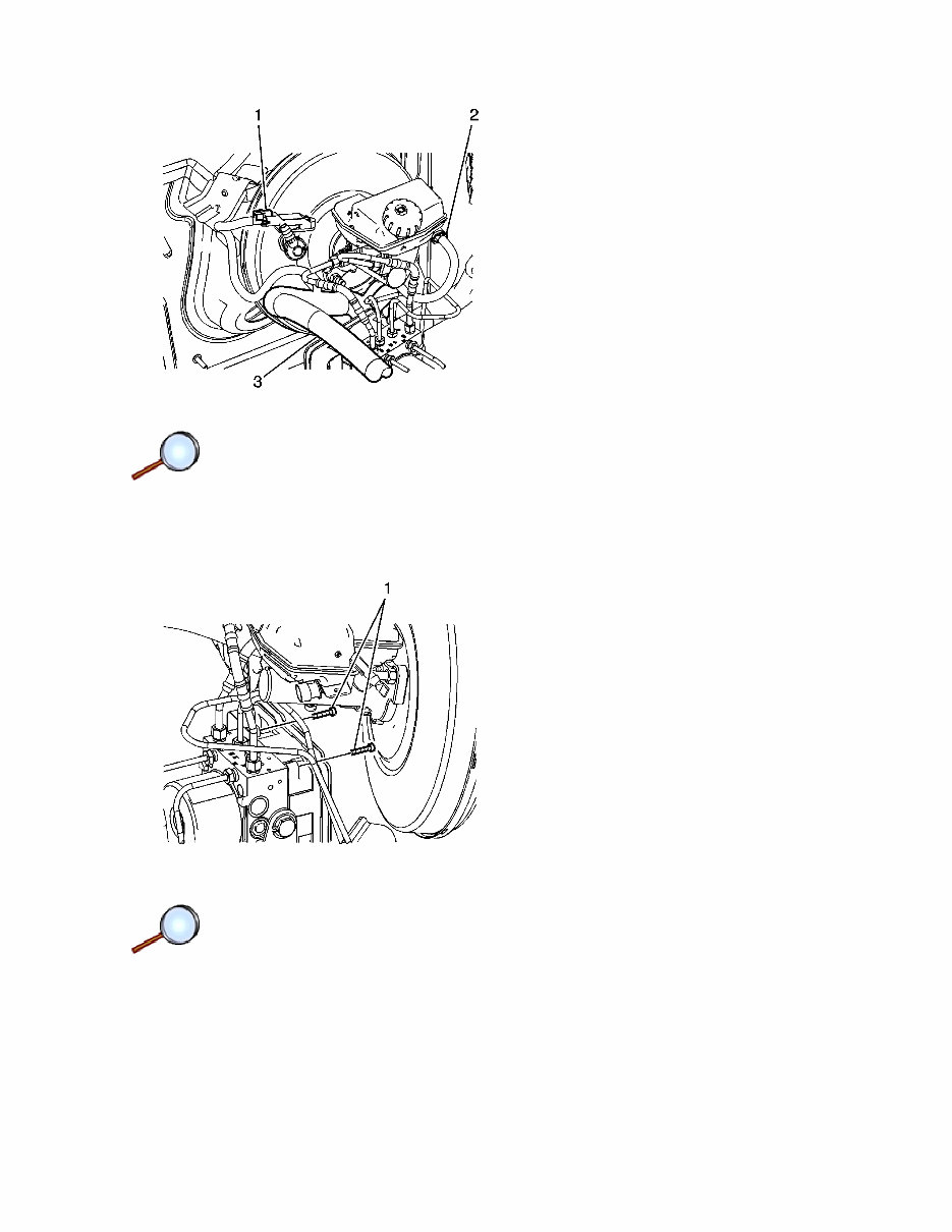
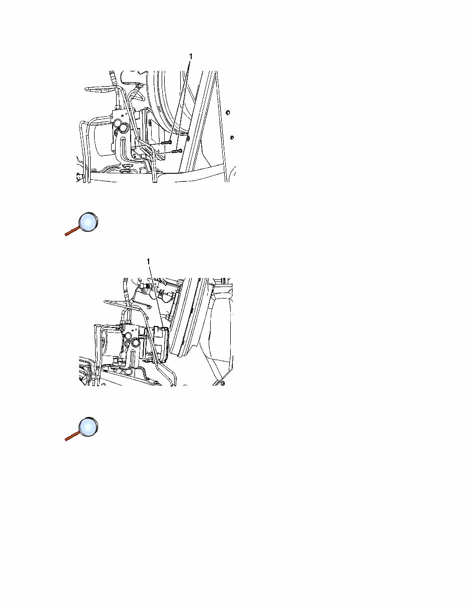
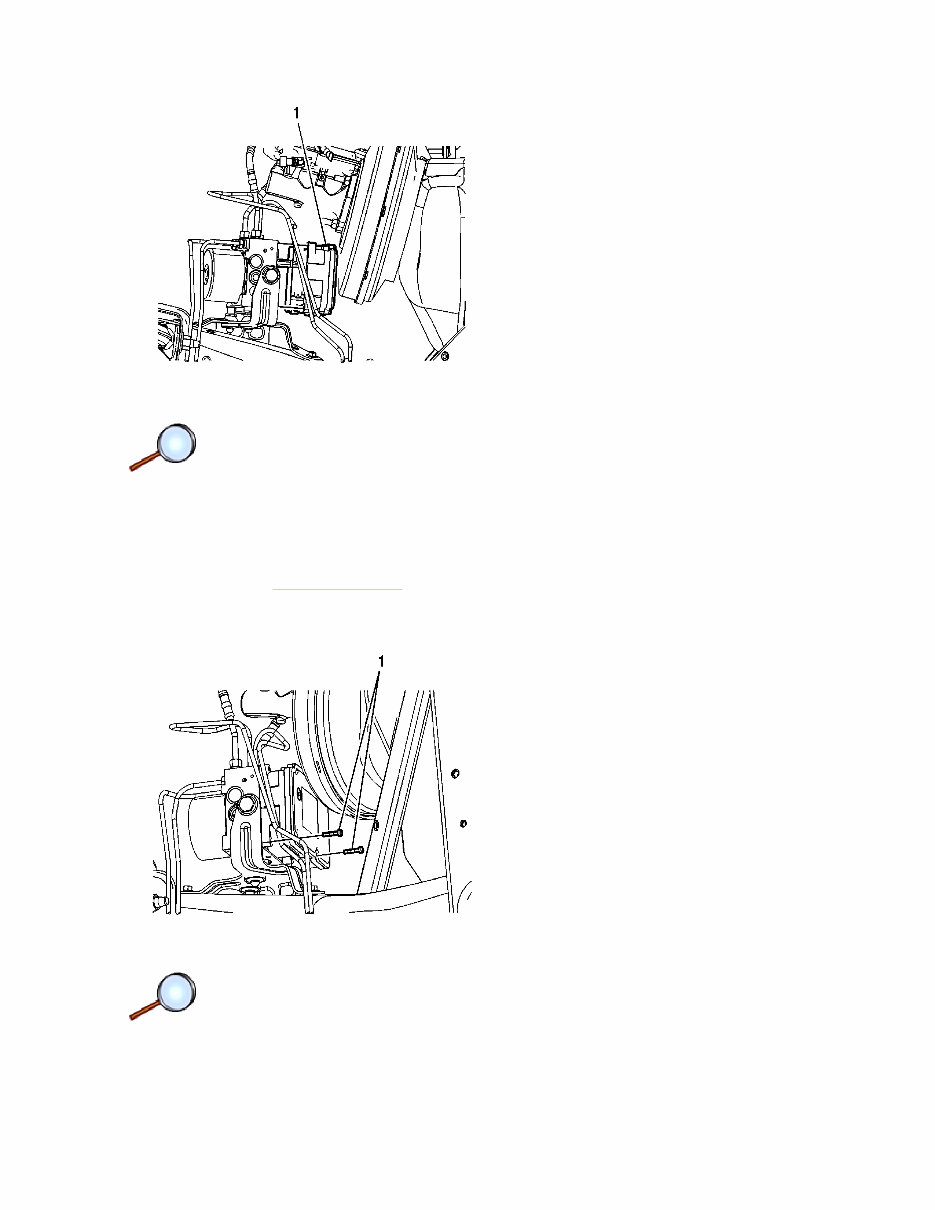
5. Disconnect the power brake booster vacuum sensor electrical connector (1). 6. Disconnect the brake fluid level indicator switch electrical connector (2). 7. Release the engine wiring harness retaining clip from the master cylinder mounting stud and position the harness (3) downward. 8. Remove the 2 upper EBCM bolts (1). Page 2 of 7 Document ID: 2101449 2/22/2010 http://localhost:9001/si/showDoc.do?docSyskey=2101449&pubCellSyskey=954&pubObj...
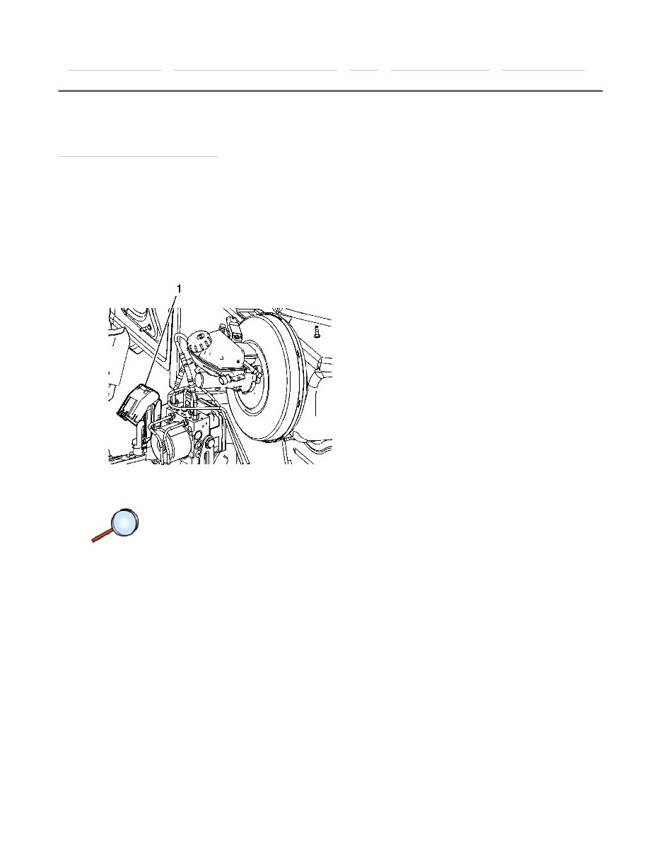
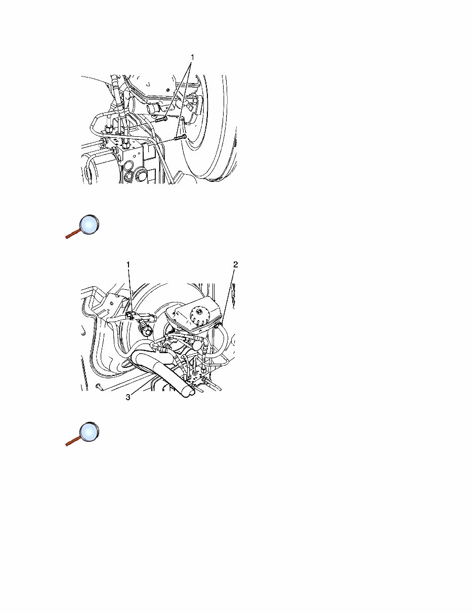
9. Remove the 2 lower EBCM bolts (1). 10. Carefully separate the EBCM (1) from the BPMV. Do not pry the components apart. Page 3 of 7 Document ID: 2101449 2/22/2010 http://localhost:9001/si/showDoc.do?docSyskey=2101449&pubCellSyskey=954&pubObj...
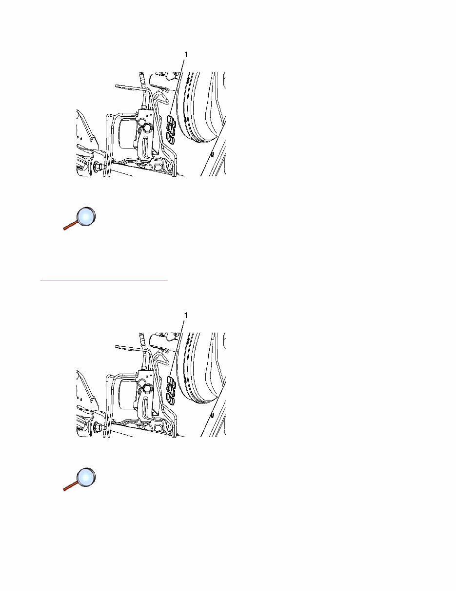
11. If installing a new EBCM, remove the 12 EBCM seals (1). 12. Clean the sealing surface of the BPMV with denatured alcohol and a clean shop cloth and allow to dry. Installation Procedure 1. If installing a new EBCM, install the 12 EBCM seals (1). Page 4 of 7 Document ID: 2101449 2/22/2010 http://localhost:9001/si/showDoc.do?docSyskey=2101449&pubCellSyskey=954&pubObj...
2. While aligning the brake pressure sensor to the BPMV, carefully install the EBCM (1) to the BPMV. Do not force the components together. Caution: Refer to Fastener Caution in the Preface section. 3. Install the 2 lower EBCM bolts (1) and tighten to 2.3 N·m (20 lb in). Page 5 of 7 Document ID: 2101449 2/22/2010 http://localhost:9001/si/showDoc.do?docSyskey=2101449&pubCellSyskey=954&pubObj...
4. Install the 2 upper EBCM bolts (1) and tighten to 2.3 N·m (20 lb in). 5. Position the engine wiring harness upward and connect the power brake booster vacuum sensor electrical connector (1). 6. Connect the brake fluid level indicator switch electrical connector (2). 7. Install the engine wiring harness (3) retaining clip to the master cylinder mounting stud. Page 6 of 7 Document ID: 2101449 2/22/2010 http://localhost:9001/si/showDoc.do?docSyskey=2101449&pubCellSyskey=954&pubObj...
If you are in need of a repair manual for your 2008 Pontiac Solstice, look no further. Our accessible repair manual software is a cost-effective and convenient alternative to traditional paper manuals. Whether you are a professional mechanic or a DIY enthusiast, this manual covers all the essential service and repair information for the Pontiac Solstice.
Gone are the days of purchasing expensive traditional service manuals in book format. Our repair manual software provides the same valuable information at a fraction of the cost and in a more accessible digital format.
Whether you are tackling brake repairs, suspension component replacements, engine troubleshooting, or standard maintenance tasks, this repair manual software for the Pontiac Solstice has got you covered. It includes comprehensive guidance on brakes, engine, suspension, steering, drivetrain, electrical systems, heating, air conditioning, and more.
By utilizing this manual, you can save a significant amount of money on vehicle repairs. Professional mechanics often charge high fees for their services, making a DIY approach with the assistance of our 2008 Pontiac Solstice repair manual software a cost-effective choice.
Our repair manual software is designed for ease of use and is compatible with Windows, Mac computers, smartphones, and tablets, ensuring accessibility across various devices.
Recently Viewed
5,521,897Happy Clients
2,594,462eManuals
1,120,453Trusted Sellers
15Years in Business
Price:
Actual Price:
2008 Pontiac Solstice Service & Repair Manual Software