

'-i..;LMES MOTORS, INC.
4CO £ast Seaonn Street
iO.i:. GROVc., IOWA 51445
1883
'
S-8310-F
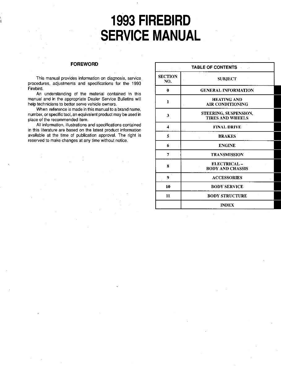
1993 FIREBIRD
SERVICE MANUAL
FOREWORD
TABLE OF CONTENTS
This manual provides information on diagnosis, service
procedures, adjustments and specifications for the 1993
Firebird.
An understanding of the material contained in this
manual and in the appropriate Dealer Service Bulletins will
help technicians to better serve vehicle owners.
When reference is made in this manual to a brand name,
number, or specific tool, an equivalent product may be used in
place of the recommended item.
All information, illustrations and specifications contained
in this literature are based on the latest product information
available at the time of publication approval. The right is
reserved to make changes at any time without notice.
SECTION
NO.
0
1
3
4
5
6
7
8
9
10
11
SUBJECT
GENERAL INFORMATION
HEATING AND
AIR CONDITIONING
STEERING, SUSPENSION,
TIRES AND WHEELS
FINAL DRIVE
BRAKES
ENGINE
TRANSMISSION
ELECTRICAL -
BODY AND CHASSIS
ACCESSORIES
BODY SERVICE
BODY STRUCTURE
INDEX
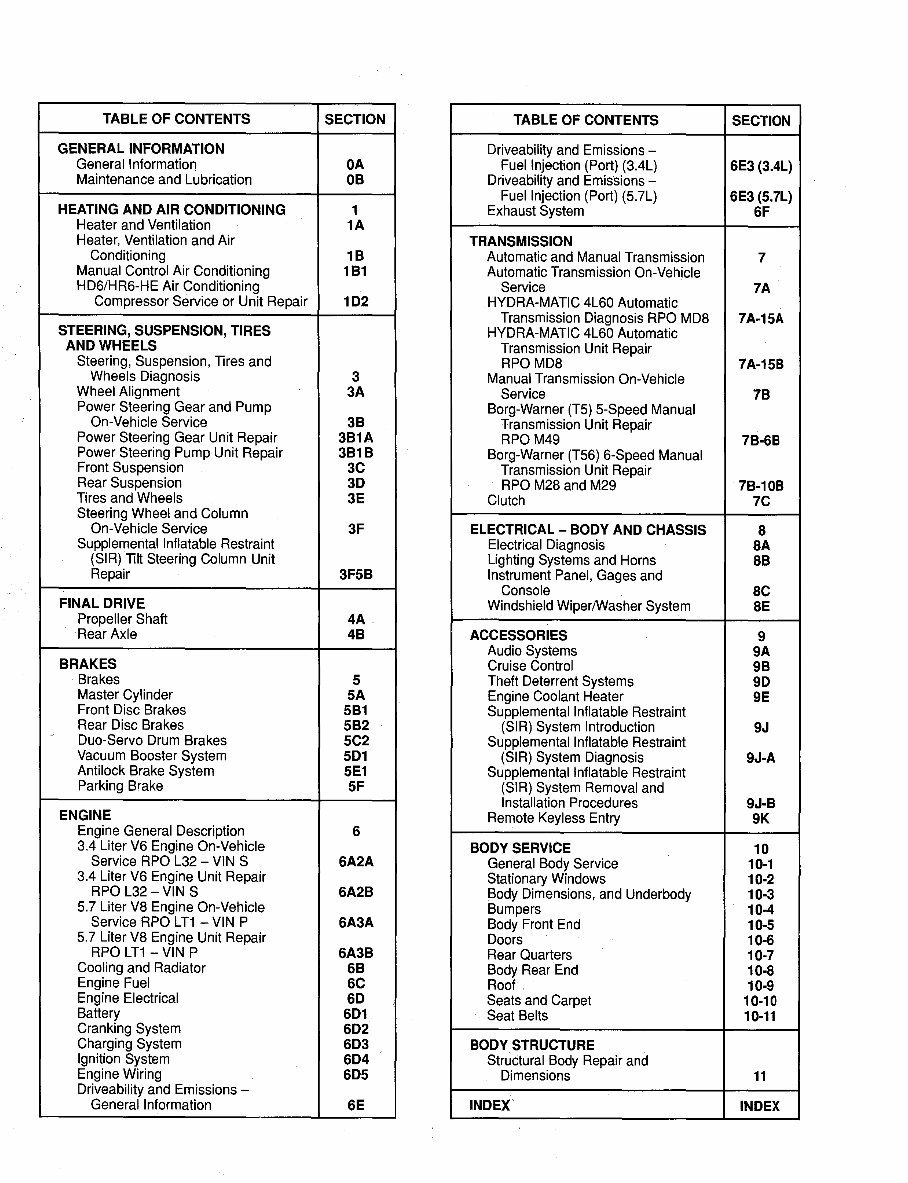
TABLE OF CONTENTS SECTION TABLE OF CONTENTS SECTION
GENERAL INFORMATION Driveability and Emissions -
General lnformatior, OA
Maintenance and Lubrication OB
Fuel Injection (Port) (3.4L) 6E3 (3.4L)
Driveability and Emissions -
HEATING AND AIR CONDITIONING 1
Fuel Injection (Port) (5.7L) 6E3 (5.7L)
Exhaust System SF
Heater and Ventilation 1A
Heater, Ventilation and Air TRANSMISSION
Conditioning 18 Automatic and Manual Transmission 7
Manual Control Air Conditioning 181 Automatic Transmission On-Vehicle
HD6/HR6-HE Air Conditioning Service 7A
Compressor Service or Unit Repair 102 HYDRA-MATIC 4L60 Automatic
STEERING, SUSPENSION, TIRES
Transmission Diagnosis RPO MD8 7A-15A
HYDRA-MATIC 4L60 Automatic
AND WHEELS
Steering, Suspension, Tires and
Transmission Unit Repair
RPO MD8 7A-158
Wheels Diagnosis 3
Manual Transmission On-Vehicle
Wheel Alignment 3A
Service 78
Power Steering Gear and Pump
On-Vehicle Service 38
Power Steering Gear Unit Repair 381A
Borg-Warner (T5) 5-Speed Manual
Transmission Unit Repair
RPO M49 78-68
Power Steering Pump Unit Repair 3818
Front Suspension 3C
Rear Suspension 30
Borg-Warner (T56) 6-Speed Manual
Transmission Unit Repair
RPO M28 and M29 78-108
Tires and Wheels 3E
Clutch 7C
Steering Wheel and Column
On-Vehicle Service 3F ELECTRICAL - BODY AND CHASSIS 8
Supplemental Inflatable Restraint
(SIR) Tilt Steering Column Unit
Electrical Diagnosis SA
Lighting Systems and Horns 88
Repair 3F5B Instrument Panel, Gages and
Console SC
FINAL DRIVE
Propeller Shaft 4A
Windshield Wiper/Washer System SE
Rear Axle 48 ACCESSORIES 9
BRAKES
Audio Systems 9A
Cruise Control 98
Brakes 5
Master Cylinder SA
Front Disc Brakes 581
Rear Disc Brakes 582
Duo-Servo Drum Brakes 5C2
Vacuum Booster System 501
Antilock Brake System 5E1
Parking Brake SF
Theft Deterrent Systems 90
Engine Coolant Heater 9E
Supplemental Inflatable Restraint
(SIR) System Introduction 9J
Supplemental Inflatable Restraint
(SIR) System Diagnosis 9J-A
Supplemental Inflatable Restraint
(SIR) System Removal and
Installation Procedures 9J-B
ENGINE
Engine General Description 6
Remote Keyless Entry 9K
3.4 Liter V6 Engine On-Vehicle
BODY SERVICE 10
Service RPO L32 - VIN S 6A2A
3.4 Liter V6 Engine Unit Repair
RPO L32 - VIN S 6A2B
5.7 Liter V8 Engine On-Vehicle
Service RPO LT1 -VIN P 6A3A
5. 7 Liter V8 Engine Unit Repair
General Body Service 10-1
Stationary Windows 10-2
Body Dimensions, and Underbody 10-3
Bumpers 10-4
Body Front End 10-5
Doors 10-6
RPO LT1 -VIN P 6A3B Rear Quarters 10-7
Cooling and Radiator 68
Engine Fuel SC
Body Rear End 10-8
Roof 10-9
Engine Electrical 60
Battery 601
Seats and Carpet 10-10
Seat Belts 10-11
Cranking System 602
Charging System 603 BODY STRUCTURE
Ignition System 604
Engine Wiring 605
Structural Body Repair and
Dimensions 11
Driveability and Emissions -
General Information SE INDEX' INDEX
1993 SERVICE MANUAL COMMENT FORM *
Use this form to advise us of any errors you might find in this manual. We also welcome
suggestions for improving the Service Manuals.
Service Manual(s) that have the error ---------------·----
Page number(s) that have the error ___________________ _
Figure number(s) that have the error ___________________ _
VIN (if available) or model and applicable options ______________ _
Describe in detail, the error found or the suggestion(s). Attach additional pages if necessary.
From: Dealer Firm Name ____________ Dealer Code _____ _
Cityfl'own State Zip Code ____ _
Name of Person Submitting This Comment Form ___________ _
Signature Date ____ Phone ( )
Mail To: Service Technology Group
Service Information Production
(030-5)
C.C.O. Building
30007 Van Dyke Ave.
Warren, Mi. 48090
* Additional comment forms at back of manual.
ST'&
Service Technology Group

1993 FIREBIRD
GENERAL INFORMATION OA· 1
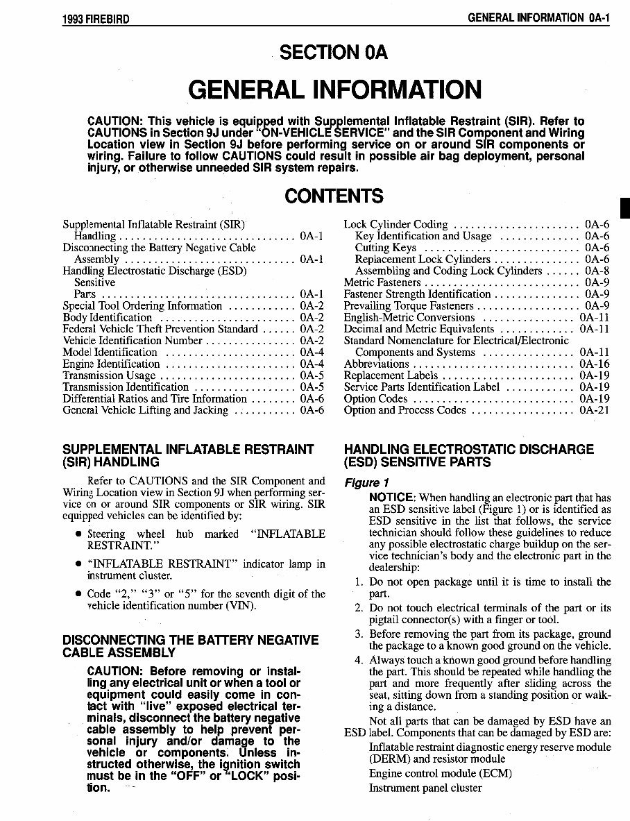
SECTION OA
GENERAL INFORMATION
CAUTION: This vehicle is equipped with Supplemental Inflatable Restraint (SIR). Refer to
CAUTIONS in Section 9J under "ON-VEHICLE SERVICE" and the SIR Component and Wiring
Location view in Section 9J before performing service on or around SIR components or
wiring. Failure to follow CAUTIONS could result in possible air bag deployment, personal
injury, or otherwise unneeded SIR system repairs.
CONTENTS
Supplemental Inflatable Restraint (SIR)
Handling ............................... OA-1
Disconnecting the Battery Negative Cable
Assembly .............................. OA-1
Handling Electrostatic Discharge (ESD)
Sensitive
Parts .................................. OA-1
Special Tool Ordering Information ............ OA-2
Body Identification ........................ OA-2
Federal Vehicle Theft Prevention Standard ...... OA-2
Vehicle Identification Number ................ OA-2
Model Identification ....................... OA-4
Engine Identification ....................... OA-4
Transmission Usage ........................ OA-5
Transmission Identification .................. OA-5
Differential Ratios and Tire Information ........ OA-6
General Vehicle Lifting and Jacking ........... OA-6
SUPPLEMENTAL INFLATABLE RESTRAINT
(SIR) HANDLING
Refer to CAUTIONS and the SIR Component and
Wiring Location view in Section 9J when performing ser-
vice on or around SIR components or SIR wiring. SIR
equipped vehicles can be identified by:
• Steering wheel hub marked "INFLATABLE
RESTRAINT."
• "INFLATABLE RESTRAINT" indicator lamp in
instrument cluster.
• Code "2," "3" or "5" for the seventh digit of the
vehicle identification number (VIN).
DISCONNECTING THE BATTERY NEGATIVE
CABLE ASSEMBLY
CAUTION: Before removing or instal·
ling any electrical unit or when a tool or
equipment could easily come in con-
tact with "live" exposed electrical ter-
minals, disconnect the battery negative
cable assembly to help prevent per-
sonal injury and/or damage to the
vehicle or components. Unless in-
structed otherwise, the ignition switch
must be in the "OFF" or "LOCK" posi-
tion. --
Lock Cylinder Coding ...................... OA-6
Key Identification and Usage .............. OA-6
Cutting Keys ........................... OA-6
Replacement Lock Cylinders . . . . . . . . . . . . . . . OA-6
Assembling and Coding Lock Cylinders ...... OA-8
Metric Fasteners ........................... OA-9
Fastener Strength Identification ............... OA-9
Prevailing Torque Fasteners .................. OA-9
English-Metric Conversions . . . . . . . . . . . . . . . . OA-11
Decimal and Metric Equivalents . . . . . . . . . . . . . OA-11
Standard Nomenclature for Electrical/Electronic
Components and Systems ................ OA-11
Abbreviations ............................ OA-16
Replacement Labels . . . . . . . . . . . . . . . . . . . . . . . OA-19
Service Parts Identification Label . . . . . . . . . . . . OA-19
Option Codes ............................ OA-19
Option and Process Codes .................. OA-21
HANDLING ELECTROSTATIC DISCHARGE
(ESD) SENSITIVE PARTS
Figure 1
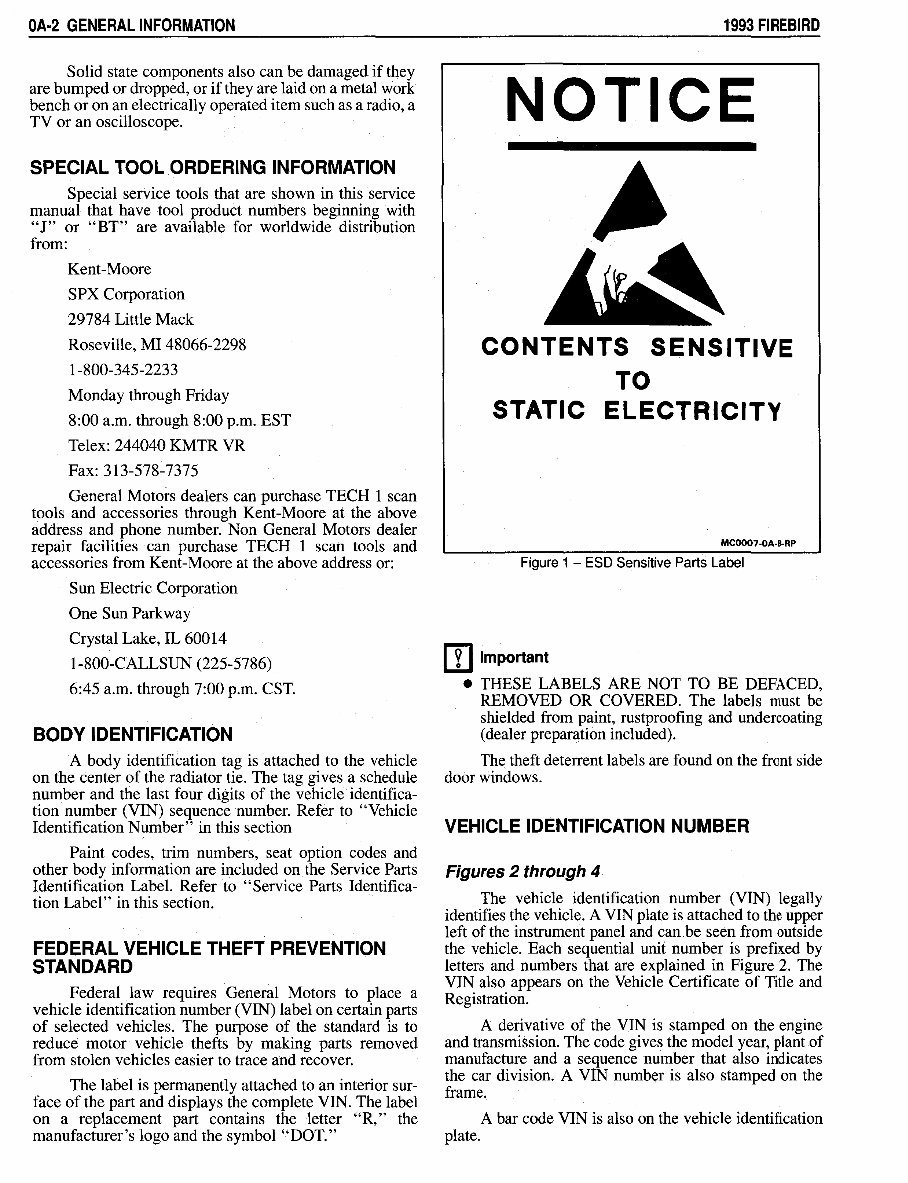
NOTICE: When handling an electronic part that has
an ESD sensitive label (Figure 1) or is identified as
ESD sensitive in the list that follows, the service
technician should follow these guidelines to reduce
any possible electrostatic charge buildup on the ser-
vice technician's body and the electronic part in the
dealership:
1. Do not open package until it is time to install the
part.
2. Do not touch electrical terminals of the part or its
pigtail connector(s) with a finger or tool.
3. Before removing the part from its package, ground
the package to a known good ground on the vehicle.
4. Always touch a known good ground before handling
the part. This should be repeated while handling the
part and more frequently after sliding across the
seat, sitting down from a standing position or walk-
ing a distance.
Not all parts that can be damaged by ESD have an
ESD label. Components that can be damaged by ESD are:
Inflatable restraint diagnostic energy reserve module
(DERM) and resistor module
Engine control module (ECM)
Instrument panel cluster
I
OA·2 GENERAL INFORMATION
Solid state components also can be damaged if they
are bumped or dropped, or if they are laid on a metal work
bench or on an electrically operated item such as a radio, a
TV or an oscilloscope.
SPECIAL TOOL ORDERING INFORMATION
Special service tools that are shown in this service
manual that have tool product numbers beginning with
"J" or "BT" are available for worldwide distribution
from:
Kent-Moore
SPX Corporation
29784 Little Mack
Roseville, MI 48066-2298
1-800-345-2233
Monday through Friday
8:00 a.m. through 8:00 p.m. EST
Telex: 244040 KMTR VR
Fax: 313-578-7375
General Motors dealers can purchase TECH 1 scan
tools and accessories through Kent-Moore at the above
address and phone number. Non General Motors dealer
repair facilities can purchase TECH 1 scan tools and
accessories from Kent-Moore at the above address or:
Sun Electric Corporation
One Sun Parkway
Crystal Lake, IL 60014
1-800-CALLSUN (225-5786)
6:45 a.m. through 7:00 p.m. CST.
BODY IDENTIFICATION
A body identification tag is attached to the vehicle
on the center of the radiator tie. The tag gives a schedule
number and the last four digits of the vehicle identifica-
tion number (VIN) sequence number. Refer to "Vehicle
Identification Number" in this section
Paint codes, trim numbers, seat option codes and
other body information are included on the Service Parts
Identification Label. Refer to "Service Parts Identifica-
tion Label" in this section.
FEDERAL VEHICLE THEFT PREVENTION
STANDARD
Federal law requires General Motors to place a
vehicle identification number (VIN) label on certain parts
of selected vehicles. The purpose of the standard is to
reduce motor vehicle thefts by making parts removed
from stolen vehicles easier to trace and recover.
The label is permanently attached to an interior sur-
face of the part and displays the complete VIN. The label
on a replacement part contains the letter "R," the
manufacturer's logo and the symbol "DOT."
1993 FIREBIRD
NOTICE
CONTENTS SENSITIVE
TO
STATIC ELECTRICITY
MC0007-0A-B-RP
Figure 1 - ESD Sensitive Parts Label
[I] Important
• THESE LABELS ARE NOT TO BE DEFACED,
REMOVED OR COVERED. The labels must be
shielded from paint, rustproofing and undercoating
(dealer preparation included).
Th~ theft deterrent labels are found on the front side
door windows.
VEHICLE IDENTIFICATION NUMBER
Figures 2 through 4
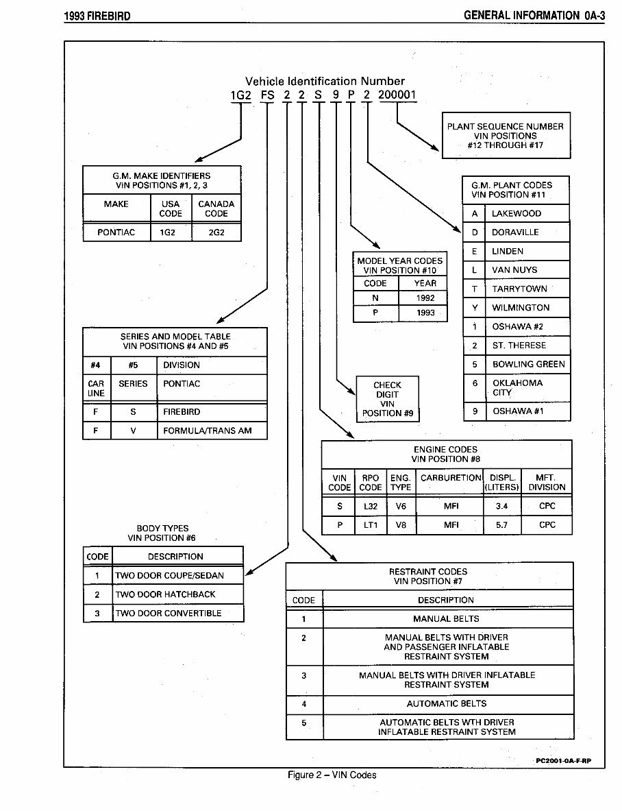
The vehicle identification number (VIN) legally
identifies the vehicle. A VIN plate is attached to the upper
left of the instrument panel and can,be seen from outside
the vehicle. Each sequential unit number is prefixed by
letters and numbers that are explained in Figure 2. The
VIN also appears on the Vehicle Certificate of Title and
Registration.
A derivative of the VIN is stamped on the engine
and transmission. The code gives the model year, plant of
manufacture and a sequence number that also indicates
the car division. A VIN number is also stamped on the
frame.
A bar code VIN is also on the vehicle identification
plate.
1993 FIREBIRD GENERAL INFORMATION OA-3
Vehicle Identification Number
1G2 FS 2 2 s 9
p
2 200001
y-- ------------ ~
PLANT SEQUENCE NUMBER
VIN POSITIONS
#12 THROUGH #17
G.M. MAKE IDENTIFIERS
VIN POSITIONS #1, 2, 3 G.M. PLANT CODES
VIN POSITION #11
MAKE USA CANADA
CODE CODE A LAKEWOOD
PONTIAC 1G2 2G2
~
D DORAVILLE
E LINDEN
MODEL YEAR CODES
VIN POSITION #10 L VAN NUYS
CODE YEAR
T TARRYTOWN
/
N 1992
p
1993
y
WILMINGTON
1 OSHAWA#2
SERIES AND MODEL TABLE
VIN POSITIONS #4 AND #5 2 ST.THERESE
#4 #5 DIVISION 5 BOWLING GREEN
CAR SERIES PONTIAC
~
CHECK
6 OKLAHOMA
LINE
DIGIT
CITY
VIN
F s FIRE BIRD
~
POSITION #9
9 OSHAWA#1
F v FORMULNTRANS AM
ENGINE CODES
VIN POSITION #8
VIN RPO ENG. CARBURETION DISPL. MFT.
CODE CODE TYPE (LITERS) DIVISION
s L32 V6 MFI 3.4 CPC
BODY TYPES
p
LT1 V8 MFI 5.7 CPC
VIN POSITION #6
~
CODE DESCRIPTION
I~
1 TWO DOOR COUPE/SEDAN
RESTRAINT CODES
VIN POSITION #7
2 TWO DOOR HATCHBACK
CODE DESCRIPTION
3 TWO DOOR CONVERTIBLE
1 MANUAL BELTS
2 MANUAL BELTS WITH DRIVER
AND PASSENGER INFLATABLE
RESTRAINT SYSTEM
3 MANUAL BELTS WITH DRIVER INFLATABLE
RESTRAINT SYSTEM
4 AUTOMATIC BELTS
5 AUTOMATIC BELTS WTH DRIVER
INFLATABLE RESTRAINT SYSTEM
PC2001-0A-F-RP
Figure 2 -VIN Codes
OA-4 GENERAL INFORMATION
VIN NUMBER PLATE
LOCATION
KC1002-0A·F-RP
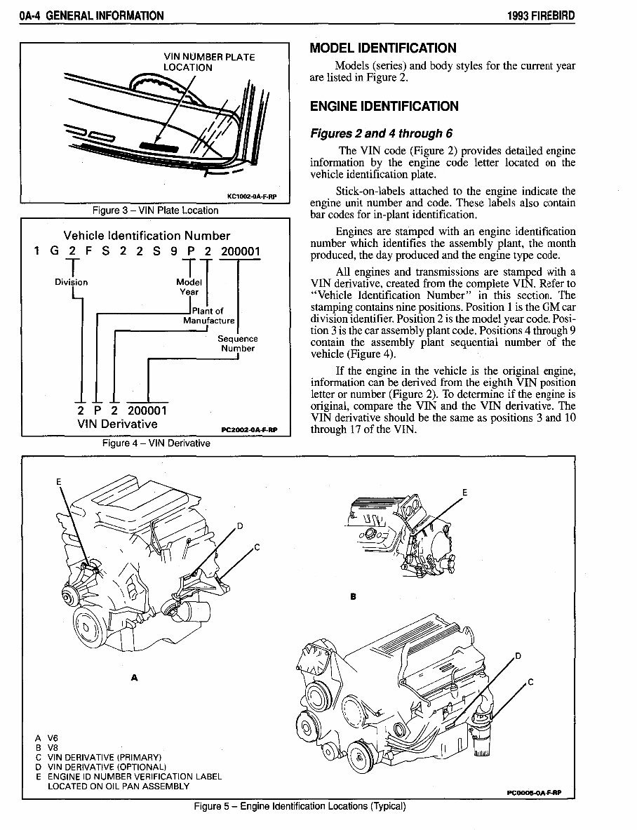
Figure 3 - VIN Plate Location
Vehicle Identification Number
1 G 2 F S 2 2 S 9 P 2 200001
Dilon MieT
Year
______ .....,-I Plant of
Manufacture
I
Sequence
Number
I
-- - -- ---
2 P 2 200001
VIN Derivative
PC2002-0A-F-RP
A V6
B V8
Figure 4 - VIN Derivative
A
C VIN DERIVATIVE (PRIMARY)
D VIN DERIVATIVE (OPTIONAL)
E ENGINE ID NUMBER VERIFICATION LABEL
LOCATED ON OIL PAN ASSEMBLY
c
1993 FIREBIRD
MODEL IDENTIFICATION
Models (series) and body styles for the current year
are listed in Figure 2.
ENGINE IDENTIFICATION
Figures 2 and 4 through 6
The VIN code (Figure 2) provides detailed engine
information by the engine code letter located on the
vehicle identification plate.
Stick-on-labels attached to the engine indicate the
engine unit number and code. These labels also contain
bar codes for in-plant identification.
Engines are stamped with an engine identification
number which identifies the assembly plant, the month
produced, the day produced and the engine type code.
All engines and transmissions are stamped with a
VIN derivative, created from the complete VIN. Refer to
"Vehicle Identification Number" in this section. The
stamping contains nine positions. Position 1 is the GM car
division identifier. Position 2 is the model year code. Posi-
tion 3 is the car assembly plant code. Positions 4 through 9
contain the assembly plant sequential number of the
vehicle (Figure 4).
If the engine in the vehicle is the original engine,
information can be derived from the eighth VIN position
letter or number (Figure 2). To determine if the engine is
original, compare the VIN and the VIN derivative. The
VIN derivative should be the same as positions 3 and 10
through 17 of the VIN.
B
c
PC0005-0A·F-RP
Figure 5 - Engine Identification Locations (Typical)
1993 FIREBIRD
TRANSMISSION USAGE
Figure 7
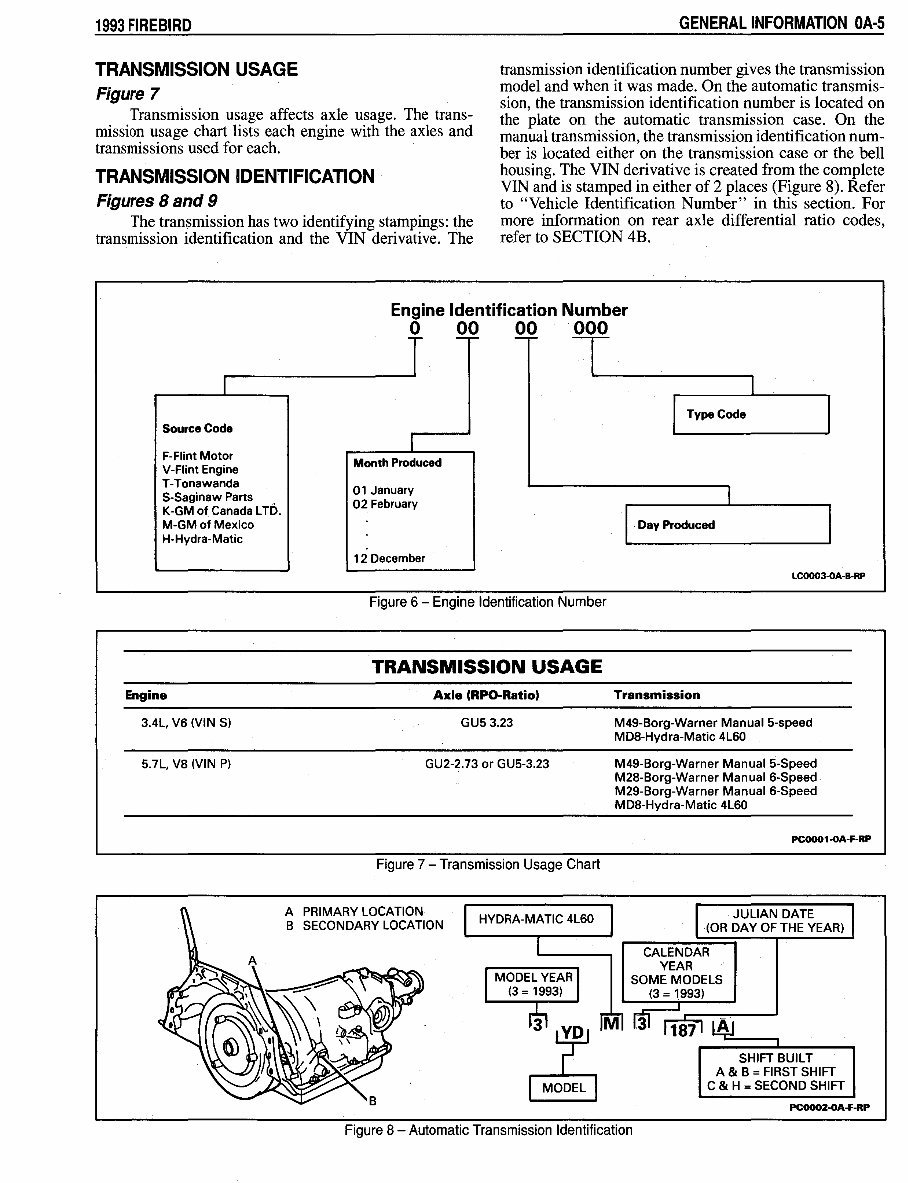
Transmission usage affects axle usage. The trans-
mission usage chart lists each engine with the axles and
transmissions used for each.
TRANSMISSION IDENTIFICATION
Figures 8 and 9
The transmission has two identifying stampings: the
transmission identification and the VIN derivative. The
GENERAL INFORMATION OA·S
transmission identification number gives the transmission
model and when it was made. On the automatic transmis-
sion, the transmission identification number is located on
the plate on the automatic transmission case. On the
manual transmission, the transmission identification num-
ber is located either on the transmission case or the bell
housing. The VIN derivative is created from the complete
VIN and is stamped in either of 2 places (Figure 8). Refer
to "Vehicle Identification Number" in this section. For
more information on rear axle differential ratio codes,
refer to SECTION 4B.
Engine Identification Number
0 00 00 000
Source Code
F-Flint Motor
V-Flint Engine
T-Tonawanda
$-Saginaw Parts
K-GM of Canada LTD.
M-GM of Mexico
H-Hydra-Matic
Engine
3.4L, V6 (VIN S)
5.7L, VS (VIN P)
Month Produced
01 January
02 February
12 December
Figure 6 - Engine Identification Number
TRANSMISSION USAGE
Axle (RPO-Ratio)
GUS 3.23
GU2-2.73 or GUS-3.23
Figure 7 - Transmission Usage Chart
A PRIMARY LOCATION
B SECONDARY LOCATION
HYDRA-MATIC 4L60
Type Code
. Day Produced
LC0003-0A-B-RP
Transmission
M49-Borg-Warner Manual 5-speed
MDS-Hydra-Matic 4L60
M49-Borg-Warner Manual 5-Speed
M28-Borg-Warner Manual 6-Speed
M29-Borg-Warner Manual 6-Speed
MDS-Hydra-Matic 4L60
PC0001-0A-F-RP
JULIAN DATE
(OR DAY OF THE YEAR)
CALENDAR
YEAR
SOME MODELS
(3 = 1993)
SHIFT BUILT
A & B = FIRST SHIFT
C & H = SECOND SHIFT
PC0002-0A-F-RP
Figure 8 - Automatic Transmission Identification
You're Reading a Preview
What's Included?
 Lifetime Access
Fast Download Speeds
Online & Offline Access
Access PDF Contents & Bookmarks
Full Search Facility
Print one or all pages of your manual
$36.99
$48.99
1993 Pontiac Firebird Service & Repair Manual Software
Viewed 43 Times Today

What's Included?
Lifetime Access
Fast Download Speeds
Online & Offline Access
Access PDF Contents & Bookmarks
Full Search Facility
Print one or all pages of your manual
$36.99
$48.99


Secure transaction
What's Included?
Lifetime Access
Fast Download Speeds
Online & Offline Access
Access PDF Contents & Bookmarks
Full Search Facility
Print one or all pages of your manual
Description
The 1993 Pontiac Firebird Service & Repair Manual is a comprehensive guide for owners and technicians, providing detailed instructions and information for servicing and repairing the iconic Pontiac Firebird model from 1993.
This manual covers a range of Firebird models, including:
- Firebird Base
- Firebird Formula
- Firebird Trans Am
It includes step-by-step procedures, diagrams, illustrations, and specifications to help maintain and repair your 1993 Pontiac Firebird. Whether you're a professional mechanic or a DIY enthusiast, this manual is an essential tool.
Keep your 1993 Pontiac Firebird in top-notch condition with the 1993 Pontiac Firebird Service & Repair Manual. Get it today and have all the information you need to keep your Firebird running smoothly.


