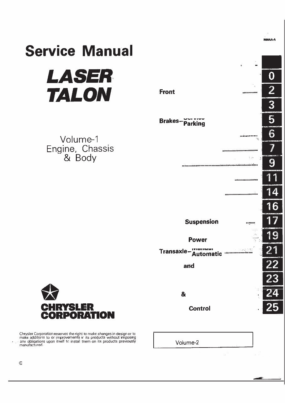
& Eclipse GROUP INDEX FOREWORD This Service Manual has been prepared with the latest service information available at the time of publication. It is subdivided into various group categories and each section contains diagnosis, disassembly, repair, and installation procedures along with complete specifications and tightening references. Use of this manual will aid in properly performing any servicing necessary to maintain or restore the high levels of performance and reliability designed into these outstanding vehicles. 1990 Mitsubishi Motors Corporation Printed in U.S.A. Introduction and Master Troubleshooting . . . . . . . . . . . . . , Lubrication and Maintenance . . . . . . . . Suspension . . . . . . . . . . . . . . Rear Axle . . . . . . . . . . . . . . . . . . . . . . . . . . . . ..‘.................... . Service . . . . . . . . . . . . . . . . . . . . . . . . . . . . . . . . . . . . . . Clutch . . . . . . . . . . . . . . . . . . . . . . . . . . . . . . . . . Cooling . . . . . . . . . . . . . . . . . Engine Intake and Exhaust . . . . . . Fuel System . . . . . . . . . . . Propeller Shaft ....................................... Rear ..... .................... . . ... Manual Steering- ..................................... Manual .... Wheels Tires ................................. Body ............................................................. Heater Air Conditioning .............. Emission Systems .............. NOTE: For Electrical, refer to “Electrical”.
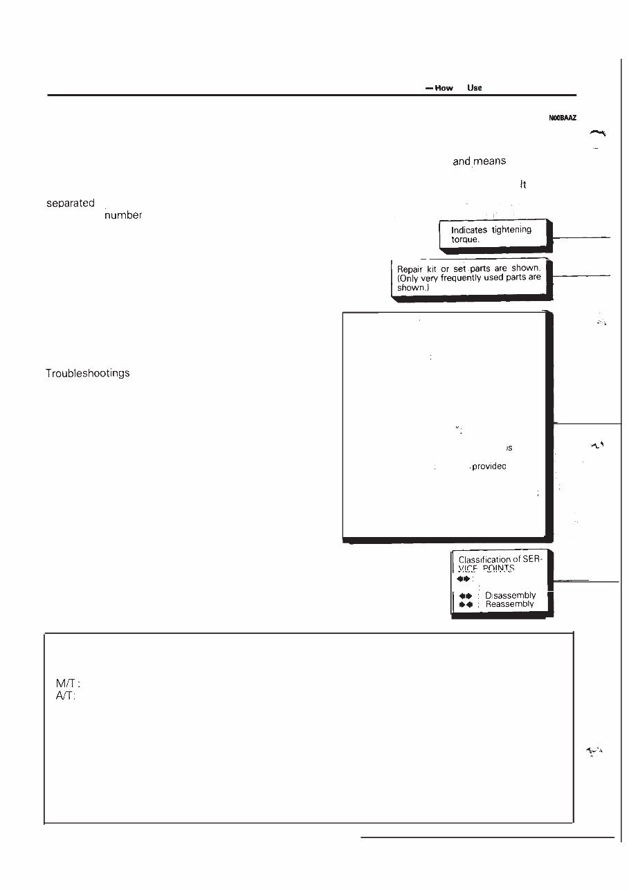
2 INTRODUCTION AND MASTER TROUBLESHOOTING to This Manual HOW TO USE THIS MANUAL CONTENTS The preceding page contains GROUP INDEX which lists the group title and group number. PAGE NUMBERS All page numbers consist of two sets of digits by a dash. The digits preceding the dash identify the of the group. The digits follow- ing the dash represent the consecutive page num- ber within the group. The page numbers can be found on the top left or right of each page. TEXT Unless otherwise specified, each service procedure covers all models. Procedures covering specific models are identified by the model codes, or similar designation (engine type, transaxle type, etc.). A description of these designations is covered in this unit under “VEHICLE IDENTIFICATION”. TROUBLESHOOTING are classified into master trouble- shooting and group troubleshooting and located as follows: The master troubleshooting is prepared when the trouble symptom relates to two or more groups and given in MASTER TROUBLESHOOTING. The group troubleshooting guide is prepared for causes of problems related to that individual group only; a troubleshooting guide is prepared for each appropriate group. LIMIT Shows the standard for judging the quality of a part or assembly on inspection the maximum or minimum value within which the part or assembly must be kept functionally or in strength. is a value established outside the range of standard value. Removal steps The numbers before part name correspond to numbers in the illustration, and indicate the order of removal. Disassembly steps The numbers before part name correspond to num- bers in the illustration, and indicate the order of disassembly. Installation steps This is provided if installa- tion cannot’be made in the reverse order of “Removal steps omitted if installa- tion in the reverse order of “Removal steps” possi- ble. Reassembly steps This is if reas- sembly cannot be made . . in the reverse order of “Disassembly steps” omitted if reassembly in the reverse order of “Dis- assembly steps” is possi- ble. SERVICE PROCEDURES The service steps are arranged in numerical order and attentions to be paid in performing vehicle service are described in detail in SERVICE POINTS. Removal l 4 Installation DEFINITION OF TERMS STANDARD VALUE Indicates the value used as the standard for judging the quality of a part or assembly on inspection or the value to which the part or assembly is corrected and adjusted. It is given by tolerance. MODEL INDICATIONS The following abbreviations are used in this manual for classification of model types. Indicates the manual transaxle, or models equipped with the manual transaxle. Indicates the automatic transaxle, or models equipped with the automatic transaxle. MPI: Indicates the multi-point injection, or engines equipped with the multi-point injection. SOHC: Indicates an engine with the single overhead camshaft, or a model equipped with such an engine. DOHC: Indicates an engine with the double overhead camshaft, or a model equipped with such an engine. Turbo: Indicates an engine with turbocharger, or a model equipped with such an engine. Non-Turbo: Indicates an engine without turbocharger, or a model equipped with such an engine. FWD: Indicates the front wheel drive vehicles. AWD: Indicates the all wheel drive vehicles. ABS: Indicates the anti-lock braking system or models equipped with the anti-lock braking system.
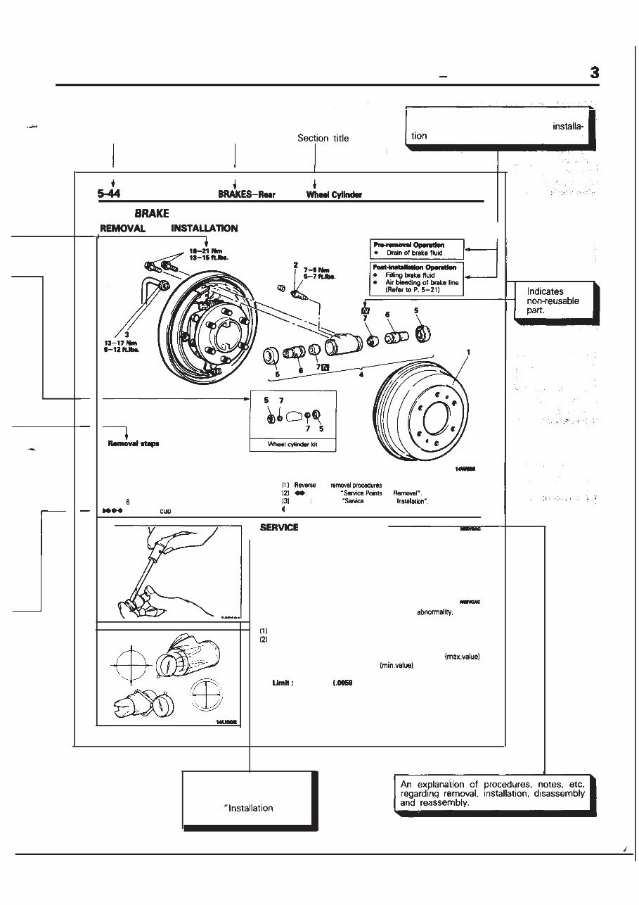
INTRODUCTION AND MASTER TROUBLESHOOTING How to Use This Manual Page number Group title Indicates the incidental operation to be performed before removal or after Brake REAR WHEEL CYLINDER AND I 1. Brake drum 2. Bleeder screw 3. Brake tube connection l * 4. Wheel cylinder assembly l e 5. Wheel cylinder boot l + Piston assembly 7. Piston NOTE the to reinstall. Refer to of l * Refer to Points of q :Nc+-r-reusab(epatts POINTS REMOVAL’ -7. REMOVAL OF PISTON CUP Using a screwdriver, remove the piston cup from the piston. INSPECTION Check the following points. and if there is any replace the entire wheel cylinder assembly. Check piston and wheel cylinder walls for rust or damage. Check clearance between the cylinder and the piston. Measure in two perpendicular directions to figure the clear- ance between the wheel cylinder inner diameter and the piston outer diameter 0.15 mm in.) NOTE If the difference is more than the limit, replace the piston and wheel cylinder as an assembly. This number corresponds to the number in “Removal steps”, “Disassembly steps”, steps” or “Reassembly steps”.
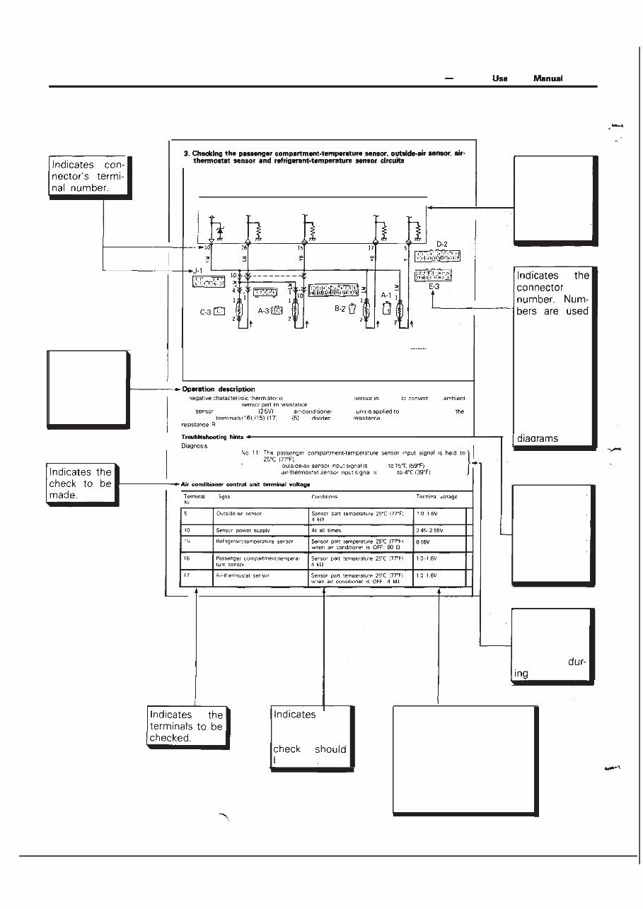
4 INTRODUCTION AND MASTER TROUBLESHOOTING How to This EXPLANATION OF THE TROUBLESHOOTING GUIDE Indicates the circuit diagram for checking (including the interface of the air conditioner control unit). I in the opera- tion descrip- tions only as necessary, and these numbers correspond to the numbers used in har- ness and com- ponent layout A employed for each order the temperature of the The power-supply of the Provides the scription of cir- cuit operation for basic under- standing. I No 12 The held No 13 The held Provides hints (including judgement) when trouble- cedures are fol- lowed. I I I Indicates the diagnosis out- put code No. and the system conditions output. the conditions un- der which the be made. Indicates the specification to be used for judgement of the check results. If there is no particular men- tion of conditions in the “Conditions” column, the column shows the specifica- tion under normal condi- tions.
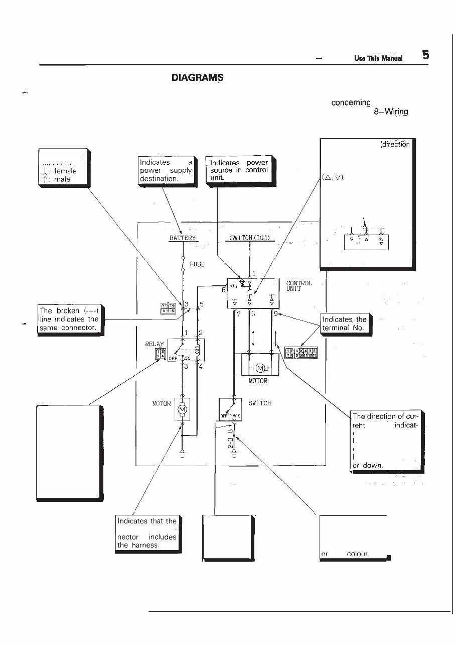
INTRODUCTION AND MASTER TROUBLESHOOTING ‘How to EXPLANATION OF CIRCUIT The symbols used in circuit diagrams are used as described below. NOTE For detailed information the reading of circuit diagrams, refer to GROUP Har- ness. The input/output of current flow) relative to the electronic control unit is indicated by symbols The (A) symbol indicates that current flows in the upward direction. Output Indicates a connector. IGNITION Input Input/output flow is ed by the arrow. In this instance, the current flow is in both directions, up The connector symbol indicates the device side connector (for an intermediate con- nector, the male side connector) as seen from the terminal front (the connector’s connection face). device side con- device side con- Indicates the branch point of a harness of a differ- ent line diameter line I Indicates that the con- nector is the direct-inser- tion type.
You're Reading a Preview
What's Included?
Lifetime Access
Fast Download Speeds
Offline Viewing
Access Contents & Bookmarks
Full Search Facility
Print one or all pages of your manual
$36.99
1990-1994 PLYMOUTH LASER All Models Service and Repair Manual
The 1990-1994 Plymouth Laser All Models Service and Repair Manual is a comprehensive guide that covers all models of the Plymouth Laser from the years 1990 to 1994. Whether you own a base model or a high-end version, this manual has got you covered with detailed instructions and diagrams.
With this manual, you'll have access to step-by-step procedures for maintenance, repairs, and service tasks for your Plymouth Laser. From simple tasks like oil changes and filter replacements to more complex repairs like engine overhauls, the manual provides clear and concise instructions, making it suitable for both professional mechanics and car enthusiasts.
Key features of the 1990-1994 Plymouth Laser All Models Service and Repair Manual:
Highly detailed and comprehensive instructions
Covers all models of the Plymouth Laser (1990-1994)
Explains routine maintenance tasks
Provides troubleshooting tips
Contains wiring diagrams for electrical systems
Includes specifications and torque values
Offers valuable guidance for both experienced and novice mechanics
Whether you need to perform a simple maintenance task or tackle a more complex repair, the 1990-1994 Plymouth Laser All Models Service and Repair Manual will be your go-to resource. Save time and money by having this manual at your disposal, allowing you to confidently work on your Plymouth Laser and keep it running smoothly for years to come.
Reviews
Q&A
Recently Viewed
5,521,897Happy Clients
2,594,462eManuals
1,120,453Trusted Sellers
15Years in Business
Price:
Actual Price:
1990-1994 PLYMOUTH LASER All Models Service and Repair Manual


 Lifetime Access




