9-2 BRAKES Hydraulic systems are used to actuate the brakes of all modern automobiles. Thesystem transports the powerrequired to forcethe frictional surfaces of the braking system together from the pedal to the indi- vidual brake units at each wheel. A hydraulic system is used for two reasons. First,fluid underpressure can be carriedto all partsof an automobile by small pipesand flexible hoses withouttakingup a significant amount of room or posingroutingproblems. Second, a greatmechanical advantage can be givento the brake pedal end of the system, and the foot pressure required to actuate the brakes can be reduced by making the surface area of the master cylinderpistonssmaller thanthat of anyof the pis- tons in thewheelcylinders or calipers. The master cylinderconsistsof a fluid reservoir alongwith a doublecylinderand pistonassembly. Double typemaster cylinders are designed to sepa- ratethefront and rear braking systems hydraulically in caseof a leak. The master cylinderconverts me- chanical motionfrom the pedalinto hydraulic pres- surewithin the lines.This pressure is translated back into mechanical motionat the wheels by eitherthe wheelcylinder(drumbrakes) or the caliper(disc brakes). Steellines carrythe brake fluid to a point on the vehicle’s framenear eachof the vehicle’s wheels. The fluid is thencarried to the calipers and wheel cylin- ders by flexibletubesin orderto allow for suspen- sion and steering movements. In drum brake systems, each wheel cylinder con- tains two pistons,oneat eitherend,which pushout- ward in opposite directions and forcethe brake shoe into contact with the drum. In disc brake systems, the cylinders are partof the calipers. At leastonecylinderin eachcaliperis used to forcethe brake pads against the disc. All pistonsemploysometypeof seal,usually made of rubber, to minimize fluid leakage. A rubber dust boot sealsthe outerend of the cylinder against dustand dirt. The bootfits around the outerend of the pistonon disc brake calipers, and around the brake actuating rod on wheelcylinders. The hydraulic system operates as follows:When at rest,the entiresystem, from the piston(s)in the mas- ter cylinder to those in the wheel cylinders or calipers,is full of brake fluid. Uponapplication of the brake pedal, fluid trapped in front of the master cylin- der piston(s)is forcedthrough the linesto thewheel cylinders. Here,it forcesthe pistonsoutward, in the caseof drum brakes, and inward toward the disc, in the caseof disc brakes. Themotion of the pistonsis opposed by returnspringsmounted outside the cylindersin drum brakes, and by spring seals,in disc brakes. Uponrelease of the brake pedal, a spring located insidethe master cylinderimmediately returns the master cylinderpistonsto the normalposition.The pistonscontaincheck valvesand the master cylinder I hascompensating ports drilled in it. These are un- covered as the pistonsreach their normalposition. The pistoncheck valves allow fluid to flow toward the wheelcylinders or calipers as the pistons withdraw. Then, as the returnspringsforce the brake padsor shoesinto the released position,the excess fluid reservoir through the compensating ports. It is during the time the pedalis in the released positionthatany fluid that hasleaked out of the system will be re- placed through the compensating ports. Dualcircuit master cylinders employ two pistons, located one behind the other,in the samecylinder. The primarypiston is actuated directlyby mechanical linkage from the brake pedal throughthe power booster. Thesecondary piston is actuated by fluid trapped between thetwo pistons.If a leakdevelops in front of the secondary piston, it movesforward until it bottoms against the front of the master cylinder, and thefluid trapped between the pistonswill operate the rear brakes. If the rearbrakes develop a leak, the pri- marypistonwill moveforwarduntil directcontact with the secondary pistontakesplace, and it will force the secondary pistonto actuate the front brakes. In eithercase, the brake pedalmovesfarther when the brakes areapplied, and lessbraking poweris avail- able. All dual circuit systems usea switchto warnthe driver whenonly half of the brake systemis opera- tional. This switch is usuallylocated in a valve body which is mounted on the firewall or the framebelow the master cylinder. A hydraulicpistonreceives pres- surefrom both circuits,eachcircuits pressure being applied to oneend of the piston.When the pressures are in balance, the piston remains stationary. When onecircuit hasa leak, however, the greater pressure in thatcircuit during application of the brakes will pushthe pistonto oneside, closingthe switchand activating the brake warninglight. In disc brake systems, this valve bodyalso con- tainsa metering valve and, in somecases, a propor- tioning valve. Themetering valve keeps pressure from traveling to the disc brakes on thefront wheels until the brake shoeson the rearwheels havecon- tacted the drums, ensuring thatthe front brakes will neverbe used alone. The proportioning valve con- trols the pressure to the rearbrakes to lessen the chance of rearwheellock-upduringvery hardbrak- ing. Warning lights may betested by depressing the brake pedal and holding it while opening one of the wheel cylinderbleeder screws. If this doesnot cause the light to go on, substitute a newlamp,make conti- nuity checks, and,finally, replace the switchas nec- essary. The hydraulic system may be checked for leaks by applyingpressure to the pedalgradually and steadily. If the pedalsinks very slowlyto the floor, the system hasa leak. This is notto beconfused with a springy or spongy feel dueto the compression of air within the lines. If the system leaks, therewill be a gradual change in the position of the pedal with a constant pressure. Check for leaks alongall lines and at wheel cylin- ders.If no external leaks are apparent, the problemis insidethe master cylinder, DISC BRAKES Instead of thetraditional expanding brakes that pressoutward against a circulardrum,disc brake systems utilizea disc (rotor) with brake padsposi- tioned on eitherside of it. An easily-seen analogy is the handbrake arrangement on a bicycle. The pads squeeze onto the rim of the bikewheel, slowing its motion.Automobile disc brakes usethe identical principlebut applythe braking effortto a separate disc instead of the wheel. Thedisc (rotor) is a casting, usually equipped with cooling fins between thetwo braking surfaces. This enables air to circulate between the braking surfaces making them lesssensitive to heat buildupand more resistant to fade. Dirt and waterdo not drastically af- fect braking actionsince contaminants arethrownoff by the centrifugal action of the rotor or scraped off the by the pads. Also, the equalclamping actionof thetwo brake pads tendsto ensure uniform,straight line stops.Disc brakes are inherently self-adjusting. There arethreegeneral typesof disc brake: 1. A fixed caliper. 2. A floatingcaliper. 3. A sliding caliper. Thefixed caliperdesign uses two pistons mounted on eitherside of the rotor (in each side of the caliper). Thecaliper is mounted rigidly and does not move. Thesliding and floatingdesigns are quitesimilar. In fact,these two types are oftenlumped together. In both designs, the padon the insideof the rotor is movedinto contact with the rotor by hydraulic force. Thecaliper, which is not held in a fixed position, movesslightly, bringing the outsidepad into contact with the rotor.There arevarious methods of attaching floatingcalipers. Somepivot at the bottomor top, and someslide on mountingbolts. In any event, the end resultis the same. DRUM BRAKES Drumbrakes employtwo brake shoesmounted on a stationary backing plate. These shoesare posi- tioned insidea circulardrum which rotates with the wheelassembly. The shoes are held in placeby springs.This allowsthemto slide toward the drums (when theyare applied) while keeping the linings and drums in alignment. Theshoes are actuated by a wheelcylinder which is mounted at thetop of the backing plate. When the brakes areapplied,hydraulic pressure forcesthe wheel cylinder’s actuating links outward. Sincetheselinks beardirectlyagainst the top of the brake shoes, the tops of the shoes are then forcedagainst the innerside of the drum.This action forcesthe bottoms of thetwo shoes to contact the brake drum by rotating the entireassembly slightly (known as servo action).When pressure within the wheelcylinderis relaxed, returnspringspull the shoesback away from the drum. Most modern drum brakes are designed to self- adjustthemselves duringapplication when the vehi- cle is moving in reverse. This motion causes both shoesto rotate very slightlywith the drum, rocking an adjusting lever,thereby causing rotationof the ad- justing screw. Somedrum brake systems are de- signed to self-adjust duringapplication whenever the brakes areapplied. This on-board adjustment system reduces the need for maintenance adjustments and keeps both the brake functionand pedal feel satisfac- tory. POWER BOOSTERS Virtuallyall modern vehiclesusea vacuum as- sisted powerbrake system to multiplythe braking forceand reduce pedal effort.Sincevacuumis always available whenthe engine is operating, the systemis
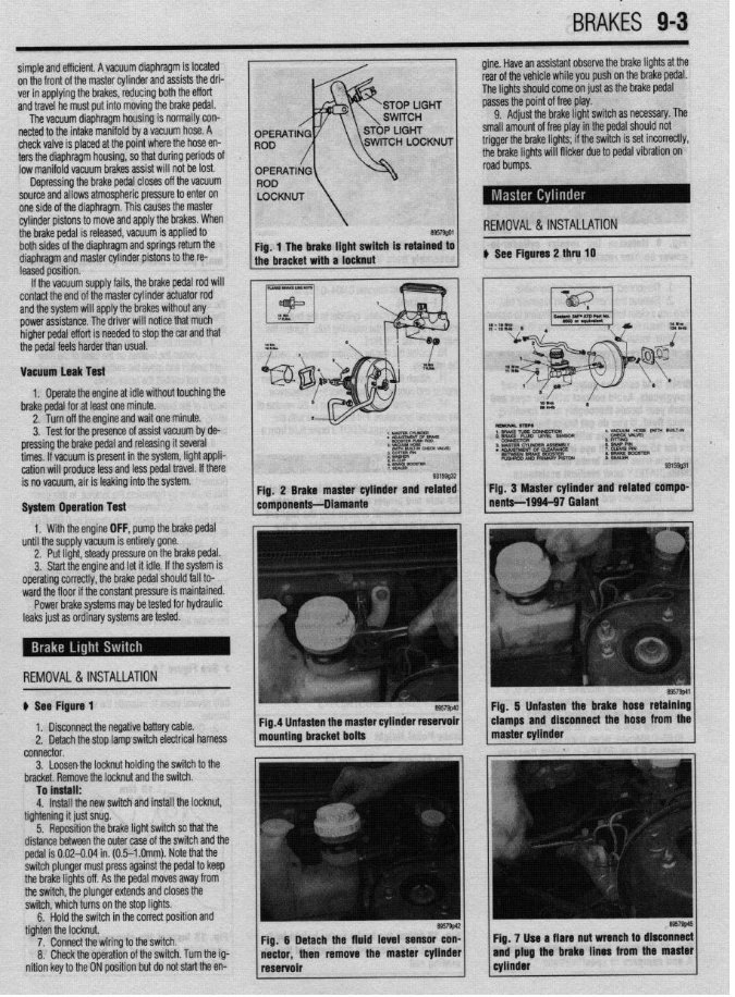
BRAKiS 9-3 simple and efficient. Avacuum diaphragm is located gine. Have an assistant observe the brake lights at the on the front ofthe master cylinder and assists the dri- rear ofthe vehicle while you push on the brake pedal. verinapplying the brakes, reducing both the effort The lights should come onjust as the brake pedal and travel he must put into moving the brake pedal. passes the point offree play. The vacuum diaphragm housing is normally con- 9. Adjust the brake light switch asnecessary. The netted to the intake manifold byavacuum hose. A small amount offree play inthe pedal should not check valve is placed atthe point where the hose en- ters the diaphragm housing, sothat during periods Of lowmanifold vacuum brakes assist will not be lost. Depressing the brake pedal closes offthe vacuum source and allows atmospheric pressure toenter on one side ofthe diaphragm. This causes the master cylinder pistons to move and apply the brakes. When the brake pedal is released, vacuum is applied to REMOVAL &INSTALLATION both sides ofthe diaphragm and springs return the diaphragm and master cylinder pistons to the re- ) See Figures2 thru 10 leased position. If the vacuum supply fails, the brake pedal rod will contact the end ofthe master cylinder actuator rod and the system will apply the brakes without any power assistance. The driver will notice that much higher pedal effort is needed to stop the car and that the pedal feels harder than usual. Vacuum leak Test 1. Operate the engine at idle without touching the brake pedal for at least one minute. 2. Turn offthe engine and wait one minute. 3. Test forthe presence ofassist vacuum byde- pressing the brake pedal and releasing it several 3 MASTER N- 188A11Ly times. If vacuum is present inthe system, light appli- . KLNsIMEm 0s CLWRANCE BETWEEN BRAKE WOSTER cation will produce less and less pedal travel. Ifthere PUSHROO AN0 PRIMARY PISTCU is no vacuum, air is leaking into the system. System Operation Test 1. With the engine OFF, pump the brake pedal until the supply vacuum is entirely gone. 2. Put light, steady pressure onthe brake pedal. 3. Start the engine and letit idle. If the system is operating correctly, the brake pedal should fallto- ward the floorif the constant pressure is maintained. Power brake systems may be tested for hydraulic leaks just asordinary systems are tested. REMOVAL&INSTALLATION $ See Figure 1 1. Disconnect the negative battery cable. 2. Detach the stop lamp switch electrical harness connector. 3. Loosenthe locknut holding the switch to the bracket. Remove the locknut and the switch. To install: 4. Install the new switch and install the locknut, tightening it just snug. 5. Reposition the brake light switch so that the distance between the outer case ofthe switch and the pedal is0.02-0.04 in.(0.5-l .Omm). Note that the switch plunger must press against the pedal to keep the brake lights off. As the pedal moves away from the switch, the plunger extends and closes the switch, which turns on the stop lights. 6. Hold the switch in the correct position and tighten the locknut. 7. Connect the wiring to the switch. 8. Check the operation ofthe switch. Turn the ig- nition key tothe ON position but donot start the en-
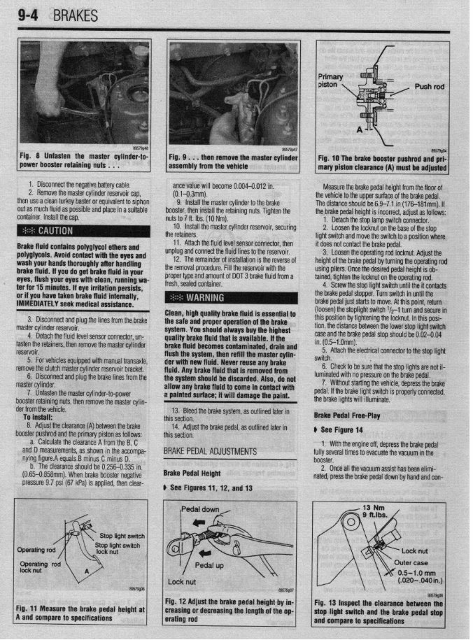
9-4 BRAKES Fig 8 Unfasten the master cylinder-to- power booster retaining nuts . . . F57g’6~ Fig. 9 . . . then removethe mastercylinder assembly from the vehicle Fig. 10 The brake booster pushrod and prf- mary piston clearance(A) must be adjusted 1. Disconnect the negative battery cable. 2. Remove the master cylinder reservoir cap, then use aclean turkey baster or equivalent to siphon out as much fluid aspossible and place inasuitable container. Install the cap. Brake fluid contains polyglycol ethersand polyglycols. Avoid contact with the eyesand wash your hands thoroughly after handling brakefluid. If you do get brakefluid in your eyes, flush your eyeswith clean, running wa- ter for 15 minutes.If eye irritation persists, or if you havetaken brakefluid internally, IMMEDIATELY seek medicalassistance. 3. Disconnect and plug the lines from the brake master cylinder reservoir. 4. Detach the fluidlevel sensor connector, un- fasten the retainers, then remove the master cylinder reservoir. 5. For vehicles equipped with manual transaxle, remove the clutch master cylinder reservoir bracket. 6. Disconnect and plug the brake lines from the master cylinder. 7. Unfasten the master cylinder-to-power booster retainino nuts, then remove the master cvlin- ante value will become 0.004-0.012 in. (0.1-0.3mm). 9. install the master cylinder tothe brake booster, then install the retaining nuts. Tighten the nuts to 7ft. Ibs. (10 Nm). 10. Install the master cylinder reservoir, securing the retainers. 11. Attach the fluidlevel sensor connector, then unplug and connect the fluidlines to the reservoir. 12. The remainder of installation is the reverse of the removal procedure. Fillthe reservoir with the proper type and amount of DOT 3 brake fluid from a fresh, sealed container. I l Clean, high quality brakefluid is essentialto the safe and properoperationof the brake system.Youshouldalways buythe highest quality brakefluid that is available. If the brakefluid becomes contaminated, drain and flush the system, then refill the master cylin- der with new fluid. Neverreuseany brake fluid. Any brakefluid that is removed from the system shouldbe discarded. Also, do not allow any brakefluid to comein contact with a painted surface; it will damage the paint. Measure the brake pedal height from the floor of the vehicle tothe upper surface ofthe brake pedal. The distance should be 6.9-7.1 in (176181mm). If the brake pedal height is incorrect, adjust as follows: 1. Detach the stop lamp switch connector. 2. Loosen the locknut on the base ofthe stop light switch and move the switch toa position where it does not contact the brake pedal. 3. Loosen the operating rod locknut. Adjust the height ofthe brake pedal by turning the operating rod using pliers. Once the desired pedal height is ob- tained, tighten the locknut on the operating rod. 4. Screw the stop light switch until the it contacts the brake pedal stopper. Turn switch in until the brake pedal just starts to move. Atthis point, return (loosen) the stoplight switch $-1 turn and secure in thisposition by tightening the locknut. In thisposi- tion, the distance between the lower stop light switch case and the brake pedal stop should be 0.02-0.04 in.(0.5-l .Omm). 5. Attach the electrical connector tothe stop light switch. 6. Check to be sure that the stop lights are not il- luminated with nopressure on the brake pedal. 7. Without starting the vehicle, depress the brake pedal. Ifthe brake light switch is properly connected, the brake lights will illuminate. der from the vefiicle. To install: 8. Adjust the clearance (A) booster pushrod ant a. Calculate tl -, between the brake Ithe primary piston as follows: le clearance A from the B,C accompa- i D. I.335 in. negative and D measurements, asshown in the nying figure.A equals B minus C minus b. The clearance should be 0.256-t (0.65-0.858mm). When brake booster I pressure 9.7psi(67kPa) is applied, then clear- 13. Bleed the brake system, asoutlined later in this section. 14. Adjust the brake pedal, as outlined later in this section. BRAKE PEDAL ADJUSTMENTS BrakePedal Height b See Figures 11, 12, and 13 BrakePedal Free-Play II See Figure 14 1. With the engine off,depress the brake pedal fullyseveral times to evacuate the vacuum inthe booster. 2. Once all the vacuum assist has been elimi- nated, press the brake pedal down byhand and con- / \ \ 0.5-1.0 mm (.020-B40in.J I I \ \ I I Fig. 12 Adjustthe brake pedal height by in- I I. @57w Cir 44 “a*., .._^*I.- 9.--l,- ---I-* L-@-L. -I Fig. 13 Inspect the clearance between thf . . - _-.L -*.a- - .. * _ .. . . ._ . rly. I I rnca~urc we urime peoai nefgnr ar A and compare to specifications creasmg or aecreasing the lengrnor me op- erating rod mop llgnt WItCh arm the brake pedal stop and compareto specifications
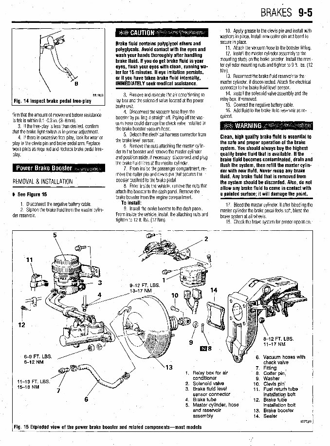
BRAKES 9-5 Inspect brake pedal free-play firm thatthe amount of movement before resistance is felt is within 0.1-0.3 in. (3-8mm). 3. If the free-play is lessthan desired, confirm thatthe brake light switch is in proper adjustment. 4. If thereis excessive free-play, look for wearor play in the clevis pin and brake pedal arm. Replace worn parts as required and recheck brake pedal free- Play* REMOVAL &INSTALLATION ' b See Figure 15 1. Disconnect the negative battery cable. 2. Siphon the brake fluid from the master cylin- der reservoir. Brakefluid contains polyglycol ethersand polyglycols. Avoid contact with the eyes and wash your hands thoroughly after handling brakefluid. If you do get brakefluid in your eyes, flush your eyeswith clean, running wa- . ter for 15 minutes.If eye irritation persists, or if you havetaken brakefluid internally, IMMEDIATELY seek medical assistance. 3. Remove and relocate theair conditioning re- lay box andthe solenoidvalve located at the power brake unit. 4. Disconnect thevacuum hosefrom the booster by pulling it straightoff. Pryingoff the vac- uum hosecould damage thecheckvalve installed in the brake booster vacuum hose. 5. Detach the electrical harness connector from the brake levelsensor. 6. Remove the nutsattaching the master cylin- derto the booster and remove the master cylinder and positionaside.If necessary, disconnect and plug the brake fluid lines at the master cylinder. 7. From insidethe passenger compartment, re- movethe cotterpin and clevis pin thatsecures the booster pushrod to the brake pedal. 8. From insidethevehicle,remove the nutsthat attach the booster to the dashpanel. Remove the brake booster from the engine compartment. To install: 9. Installthe brake booster to the dashpanel. From insidethe vehicle,installthe attaching nutsand tightento 12 ft. Ibs. (17 Nm). 10. Applygrease to the clevis pin and install with washers in place. Installnewcotterpin and bend to secure in place. 11. Attach the vacuum hoseto the booster fitting. 12. Installthe master cylinderassembly to the mounting studson the brake booster. Installthe mas- ter cylindermounting nutsandtightento 9 ft. Ibs. (12 Nm). 13. Reconnect the brake fluid reservoir to the master cylinder, if disconnected. Attach the electrical connector to the brake fluid levelsensor. 14. Installthe solenoidvalveassembly andthe relaybox, if removed. 15. Connect the negative battery cable. 16. Add fluid to the brake fluid reservoiras re- quired. Clean, high quality brakefluid is essentlalto the safe and properoperationof the brake system. Youshouldalways buythe highest quality brakefluid that is available. If the brakefluid becomes contaminated, drain and flush the system, then refill the mastercylin- der with new fluid. Neverreuseany brake fluid. Any brakefluid that is removed from the system shouldbe discarded. Also, do not allow any brakefluid to comein contact with a painted surface;it will damage the paint. 17. Bleed the master cylinder. If afterbleeding the master cylinder the brake pedal feelssoft, bleed the brake system at all wheels. 18. Check the brake system for properoperation. * rn( mr '13 1. Relay box for air conditioner l-13 t- I, Ltx5. 5-18 NM 2. Solenoid valve 3. Brake fluid level sensor connector 6 4. Brake tube 5. Master cylinder, hose and reservoir assem biy Fig. 15 Exploded view of the power brake booster and related components-most models 12. 13. 14. Fitting 1 Cotter pin; Washer 1 Clevis pin’ Fuel retuti tub8 installatiob bolt Brake tUd8 installatioh bolt Brake booster Sealer 89579glt
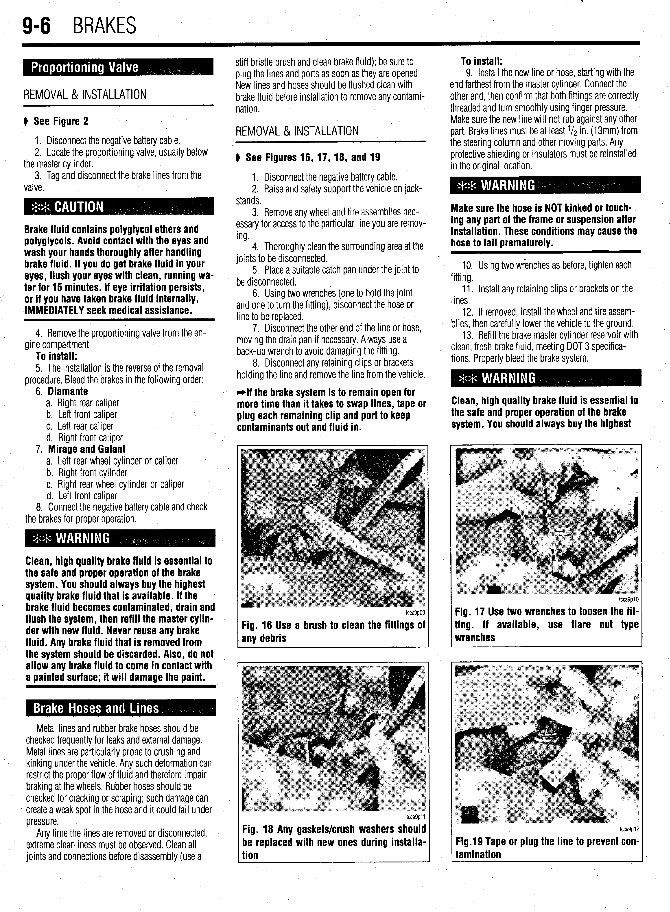
. 9-6 BRAKES REMOVAL & INSTALLATION I) See Figure 2 1. Disconnect the negative battery cable. 2. Locate the proportioning valve, usually below the master cylinder. 3. Tag and disconnect the brake lines from the valve. Brake fluid contains poiygiycoi ethersand poiygiycois. Avoid contact with the eyesand wash your hands thoroughly after handling brakefluid. if you do get brakefluid in your eyes, flush your eyeswith clean, running wa- ter for 15 minutes.if eye irritation persists, or if you havetaken brakefluid internally, IMMEDIATELY seek medicalassistance. 4. Remove the proportioning valve from the en- gine compartment. To install: 5. The installation isthe reverse ofthe removal procedure. Bleed the brakes in the following order: 6. Diamante a. Right rear caliper b. Left front caliper c. Left rear caliper d. Right front caliper 7. Mirage and Gaiant a. Left rear wheel cylinder or caliper b. Right front cylinder c. Right rear wheel cylinder or caliper d. Left front caliper 8. Connect the negative battery cable and check the brakes for proper operation. Clean, high quality brakefluid is essentialto the safe and properoperationof the brake system. Youshouldalways buythe highest quality brakefluid that is available. if the brakefluid becomes contaminated, drain and flush the system,then refill the master cyiin- der with new fluid. Neverreuse any brake fluid. Any brakefluid that is removed from the system shouldbe discarded. Also, do not allow any brakefluid to comein contact with a paintedsurface;it will damage the paint. Metal lines and rubber brake hoses should be checked frequently for leaks and external damage. Metal lines are particularly prone to crushing and kinking under the vehicle. Any such deformation can restrict the proper flowoffluid and therefore impair braking atthe wheels. Rubber hoses should be checked for cracking or scraping; such damage can create aweak spot inthe hose and it could fail under pressure. Any time the lines are removed or disconnected, extreme cleanliness must be observed. Clean all joints and connections before disassembly (use a stiffbristle brush and clean brake fluid); be sure to plug the lines and ports as soon as they are opened. New lines and hoses should be flushed clean with brake fluid before installation to remove any contami- nation. REMOVAL&INSTALLATION ) See Figures16, 17, 18, and 19 1. Disconnect the negative battery cable. 2. Raise and safely support the vehicle on jack- stands. 3. Remove any wheel and tireassemblies nec- essary for access tothe particular line you are remov- ing. 4. Thoroughly clean the surrounding area atthe joints to be disconnected. 5. Place a suitable catch pan under the joint to be disconnected. 6. Using two wrenches (one to hold the joint and one toturn the fitting), disconnect the hose or line to be replaced. 7. Disconnect the other end ofthe line or hose, moving the drain pan if necessary. Always use a back-up wrench to avoid damaging the fitting. 8. Disconnect any retaining clips or brackets holding the line and remove the line from the vehicle. -if the brakesystemis to remain openfor moretime than it takes to swap lines, tape or plug eachremainingclip and port to keep contaminants out and fluid in. I tcca9p09 tcca9p09 Fig. 16 Use a brushto clean the fittings of Fig. 16 Use a brushto clean the fittings of any debris any debris tcca9pll Fig. 18 Any gaskets/crush washers should be replaced with new ones during instaiia- tion To install: 9. Install the new line or hose, starting with the end farthest from the master cylinder. Connect the other end, then confirm that both fittings are correctly threaded and turn smoothly using finger pressure. Make sure the new line will not rub against any other part. Brake lines must be at least l/z in.(13mm) from the steering column and other moving parts. Any protective shielding or insulators must be reinstalled inthe original location. Makesure the hose is NOT kinkedor touch- ing any part of the frame or suspension after installation. These conditionsmaycause the hoseto fail prematurely. 10. Using two wrenches asbefore, tighten each fitting. Ii. Install any retaining clips or brackets on the lines. 12. If removed, install the wheel and tire assem- blies, then carefully lower the vehicle tothe ground. 13. Refill the brake master cylinder reservoir with clean, fresh brake fluid, meeting DOT 3 specifica- tions. Properly bleed the brake system. Clean, high quality brakefluid is essentialto the safe and properoperationof the brake system.Youshouldalways buythe highest tcca9p10 Fig. 17 Usetwo wrenchesto loosen the fit- ting. If available, use flare nut type wrenches tcca9p12 Fig.19Tape or plug the line to prevent con- tamination
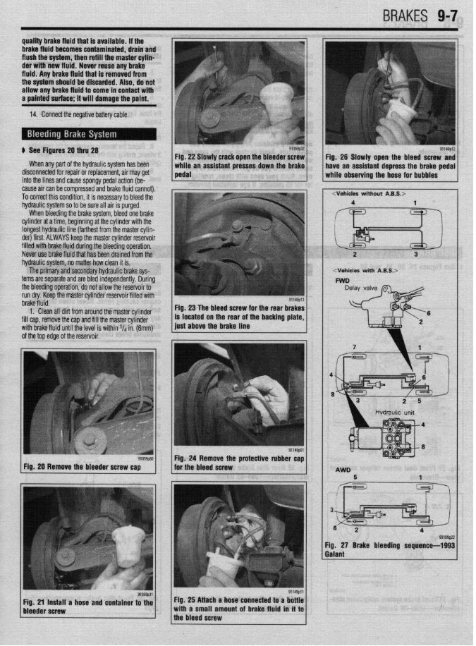
BRAKES 9-7 b See Figures 20 thru 28 When any part ofthe hydraulic system has been disconnected for repair or replacement, airmay get into the lines and cause spongy pedal action (be- cause aircan be compressed and brake fluid cannot). Tocorrect this condition, it is necessary to bleed the hydraulic system soto be sure all air is purged. When bleeding the brake system, bleed one brake cylinder atatime, beginning atthe cylinder with the longest hydraulic line (farthest from the master cylin- der) first. ALWAYS keep the master cylinder reservoir filled with brake fluid during the bleeding operation, Never use brake fluid that has been drained from the hydraulic system, nomatter how clean it is. The primary and secondary hydraulic brake sys- terns are separate and are bled independently. During the bleeding operation, donot allow the reservoir to run dry. Keep the master cylinder reservoir filled with Fig. 22 Slawly crackopenthe bleederscrew brake fluid. 1. Clean all dirt from around the master cylinder fill cap, remove the cap and fill the master cylinder with brake fluiduntil the level is within V4 in.(6mm) ofthe top edge ofthe reservoir. Fig, 23 The bleed screw for the rear brakes 91059p30 Fig. 20 Remove the bleeder screw cap Fig. 28 Slowly open the bleed screw and <Vehicles with A.&S.> Fig, 27 Brake bleeding sequence-1993 Galant Fig. 25 Attacha hose connected to a bottle with a small amountof brake fluid in it to the bleed screw
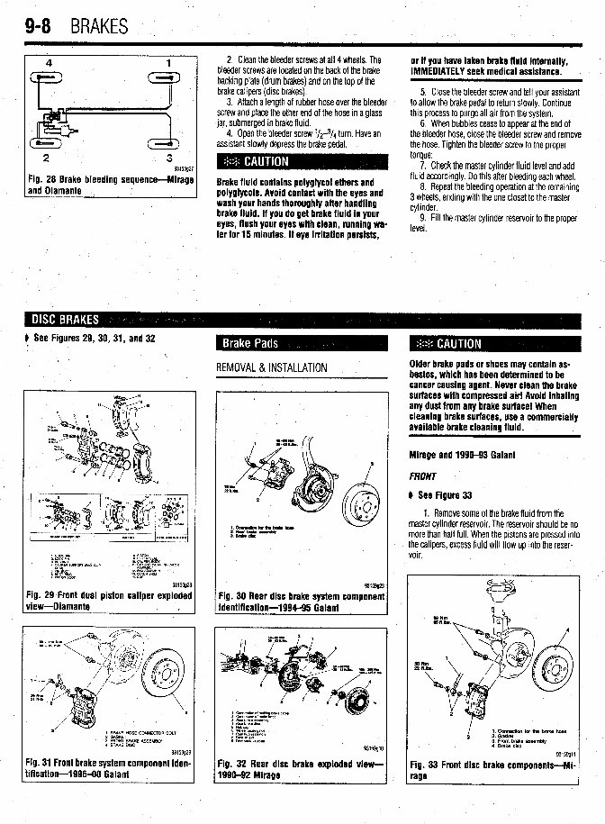
9-8 BRAKES 2 3 93159g27 Fig. 28 Brake bleeding sequence-Mirage and Diamante 1 2, Clean the bleeder screws atall 4 wheels. The bleeder screws are located on the back ofthe brake backing plate (drum brakes) and on the top ofthe brake calipers (disc brakes). 3. Attach a length of rubber hose over the bleeder screw and place the other end ofthe hose ina glass jar, submerged in brake fluid. 4. Open the bleeder screw l/r3/4 turn. Have an assistant slowly depress the brake pedal. Brake fluid contains polyglycol ethersand poiygiycois. Avoid contact with the eyes and wash your hands thoroughly after handling brakefluid. if you do get brakefluid in your eyes, flush your eyeswith clean, running wa- ter for 15 minutes.if eye irritation persists, or if you have taken brakefluid internally, IMMEDIATELY seek medicalassistance. 5. Close the bleeder screw and tellyour assistant to allow the brake pedal to return slowly. Continue thisprocess to purge all airfrom the system. 6. When bubbles cease to appear atthe end of the bleeder hose, close the bleeder screw and remove the hose. Tighten the bleeder screw to the proper torque: 7. Check the master cylinder fluidlevel and add fluid accordingly. Do this after bleeding each wheel, 8. Repeat the bleeding operation atthe remaining 3 wheels, ending with the one closet to the master cylinder. 9. Fillthe master cylinder reservoir tothe proper level. # See Figures 29, 30, 31, and 32 REMOVAL &INSTALLATION . I. C”lDE PIN 8 mm 2 LdcK Pm 9 PlSToN SEAL 3 WSHINO 10 WPER BODY 4 CALIPER 9lJPwRT ,pM. cue sH’YlcYaT , 11 PmE~~yvEm INLKATclR : EiT Rim 12 PAD As&&w 7 PWON mm ;: w&E” SHlM , 93159g28 Fig. 29 Front dual piston caliper exploded view-Diamante ‘a L 1. BRAKE HOSE CONNECTOR BOLT 2. GASKET ’ 3. FRONT BRAKE ASSEMBLY 4. BRAKE DISC 93159g; Fig. 31 Frontbrakesystem component iden tification-1996-00 Gaiant !9 I- 93159g23 Fig. 30 Rear disc brake systemcomponent identification-1994-95 Galant 3 Rear brake ar?.embiy 4 Rear Drake dnc 5 Hubcap 6 Wheel baanng tit 7 Flew hub assemblv 8 chlstshteki 9 DISCbrake adapter 93159glC Fig. 32 Rear disc brake exploded view- 1996-92 Mirage Olderbrake padsor shoesmay containas- bestos,which has beendetermined to be cancercausing agent. Neverclean the brake surfaces with compressed air! Avoid inhaling any dustfrom any brake surface!When cieanlng brakesurfaces,use a commercially available brake cleaningfluid. Mirage and 1990-93 Gaiant * FRONT @See Figure 33 1. Remove some ofthe brake fluid from the master cylinder reservoir. The reservoir should be no more than half full.When the pistons are pressed into the calipers, excess fluid will flowupinto the reser- voir. I 1. Cons for the brake hose 3 2. Gasket 3. Front brake assembly 4. Brake disc 93159911 Fig. 33 Front disc brake components-Mi- rage
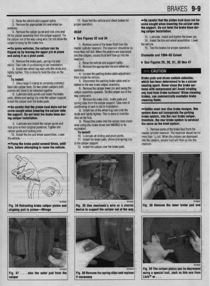
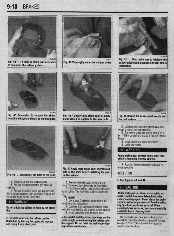
2. Raise the vehicle and support safely. 3. Remove the appropriate tire and wheel as- semblies. 11. Road test the vehicle and check brakes for proper operation. *Be careful that the piston boot doesnot be- comecaught when lowering the caliper onto +ha n,.nnnr) lh nnt t&at thm hr&a hnra rlnr- 4. Remove the calmer auide and lock Dins and REAR lift the caliper assembly’from the caliper support. Tie the caliper out of the way using wire. 00 not allow the caliper to hang bythe brake line. *On some vehicles, the caliper can be flipped up by leaving the upperpin in place and usinuit as a oivot ooint. ---- sa - . -. 5. Remove the brake pads, spring clip and cl7knr T&n nn+n ,-A nrdtinninntn sir-4 inc+alhtinn u See Figures 32 and 34 13. Lubricate, install and tighten the lower pin. * 14. Install the tire and wheel assemblies. Lower 1, Remove some ofthe brake fluid from the the vehicle. master cylinder reservoir. The reservoir should be no 15. Test the brakes for proper operation: more than half full.When the p istons are depressed into the calioers. excess fluid \n 3 111,113.,(lhC ,,“LC “I p”3”‘““H’y I” a,u IIIaLcuIaLt”II. 6. Install two wheel lugnuts onto the studs and : lightly tighten. This is done to hold the disc on the hub. To install: 7. Use a large C-clamp to compress piston(s) back into caliper bore. On two piston calipers both pistons will have to be retracted together. 8. Lubricate slide points and install the brake pads, shims and spring clipont-+‘- --“n-* n**nnnA reservoir. /ill flowupinto the 2. Raise the vehicle and support safely. stire and wheel as- 3. Remove the appropriate semblies. 4. Loosen the parking bra from inside the vehicle. 5. Disconnect the parking brake cable end in- stalled to the rear brake caliper assembly. 6. Remove the caliper lower pin and swing the caliper assembly upwards. Tie the caliper out ofthe way using wire. Dlamante and 1994-00 Galant k See Figures29,30,31,35 thru 47 Brakepadsandshoescontainasbestos, which has beendetermined to be a cancer causing agent. Neverclean the brakesur- faces with compressed air! Avoid inhaling any dustfrom brakesurfaces! When cleaning brakes.use commerciallv avallable brake Ike cable adjustment Install the caliper over the brake ,..uuG. 7. Remove the outer shim, brake pads and . ie caliper support. Take note of soring clips from tl nositibning of eact 8 IndalI twn cleaning flutds. - *Be careful that the piston boot does not be- comecaughtwhen lowering the caliper onto the support.Do not twist the brakehose dur- ing caliper installation. Ito aidin installation. “. llluLull L..V ofthe wheel lug nuts onto the studs and lightly tighten. This is done to hold the disc on the hub. Cl Thrm-l the nictnn into thP r!alinar hnre rlnrk- *Unlike mostrear disc brakedesigns,this system doesnot incorporate the parking brakesystem, into the rear brakecaliper, therefore, the rear brakesystemis serviced 9. Lubricate and install the caliper guide and lock pins in their original positions. Tighten the : caliper guide and locking pins. 10. Install the tire and wheel assemblies. Lower the vehicle. t *Pump the brakepedal several times, until i firm, before attempting to movethe vehicle. V. ,,,lV”” ,,,V ~,“L”,’ III1” .IIV “..*.prv, ““I., “.“-a. wise using disc brake driver toolMB9f52 or its equivalent. To install: 10. Lubricate all sliding and pivot points. 11. Install the brake pads, shims and spring clip to the caliper support. 12. Install the caliper over ” ’ -’ ---I~ me oraxe paas. the sameas the front system. 1. Remove some ofthe brake fluid from the master cylinder reservoir. The reservoir should be no more than r/a full.When the pistons are depressed into the calipers, excess fluid will flowupinto the reservoir. 93159#2 Fig. 34 Retracting brake caliper piston and Fig. 35 Use mechanic’s wire or a similar aligning pad to piston-hlirage device to supportthe caliper out of the way Fig. 36 Remove the inner brake pad and . . . 93159p33 Fig, 37 . . . also the outer pad from the caliper Fig. 39 Thecaliper piston can be depressed Fig. 38 Remove the spring clips and replace if necessary using a special tool, such as this one from Lisle@ or . . .
l 9-10 BRAKES Fig. 40 . . . a large C-clamp will also work to compress the caliper piston then makesure to lubricate the Fig. 46 . . . then install the shim on the pads Fig. 47 Apply more brakequiet over the out- /, the vehicle .Is/l* wde of the sham before installing the pads 2. Raise the vehicle and support safely. 3. Remove the appropriate tire and wheel as- semblies. 4. Remove the caliper guide and lock pins and lift the caliper assembly from the caliper support. Tie the caliper out ofthe way using wire. ( I ’ 5. Remove the brake pads, spring clip and shims. Take note ofpositioning to aid installation. 6. Do not allow the caliper to hangby the brake ’ line. *On somevehicles, the caliper can be flipped up by leaving the upperpin in place and using it as a pivot point. Install the wheel lug nuts onto the studs and lightly tighten. This is done to hold the disc on the hub. To install: 7. Use a large C-clamp to compress the pis- ton(s) back into caliper bore. _ 8. Lubricate slide points and install the brake pads, shims and spring cliponto the caliper support. 9. Install the caliper over the brake pads. *Be careful that the piston boot does not be- comecaught when lowering the caliper onto the support.Do not twist the brake hosedur- ing caliper installation. Olderbrakepadsor shoesmay containas- bestos,which has beendetermined to be cancercausing agent. Neverclean the brake surfaces with compressed air! Avoid inhaling any dust from any brakesurface! When cleaning brake surfaces, use a commercially available brake cleaningfluid. IO. Lubricate and install the caliper guide and lock pins intheir original positions. 11. Tighten the guide and locking pins to 54 ft. Ibs. (75 Nm) on the front, and 20ft. Ibs. (27 Nm) on the rear, 12. install the tire and wheel assemblies. 13. Lower the vehicle. Pump brake pedalseveral tlmes, until firm, before attempting to movevehicle. 14. Road test the vehicle and check brakes for proper operation. INSPECTION p See Figures 48 and 49 The disc brake pads have wear indicators that contact the brake disc when the brake pad thickness becomes 0.08 in.(2.0mm) and emit asquealing sound to worn the driver.
Owning a 1990 Plymouth Colt means having access to a comprehensive repair manual that is perfect for both professional mechanics and DIY enthusiasts. This manual provides all the necessary service information for fixing brakes, engine, suspension, steering, drivetrain, electrical problems, heat, and air conditioning. Whether it's standard maintenance or specific repairs, this manual has got you covered.
In the past, obtaining a traditional service manual in book format was costly and inconvenient. However, this repair manual offers a more affordable and convenient alternative, available in a digital format compatible with Windows, Mac, smartphones, and tablets. By utilizing this manual, you can save a significant amount of money on vehicle maintenance and repairs, as it provides all the essential guidance for working on your own vehicle.
So, whether you need to address brake issues, replace suspension components, or perform standard maintenance, this repair manual for the 1990 Plymouth Colt is the ideal resource to assist you every step of the way.