MANUALE STAZIONE DI SERVIZIO APE TM Benzina WORKSHOP MANUAL This workshop manual has been drawn up by PIAGGIO & C. Spa to be used by the workshops of Piaggio dealers. This manual is addressed to Piaggio service mechanics who are supposed to have a basic knowledge of mechanics principles and of vehicle fixing techniques and procedures. Any important changes made to the vehicles or to specific fixing operations will be promptly reported by updates to this manual. Nevertheless, no fixing work can be satisfactory if the necessary equipment and tools are unavailable. It is therefore advisable to read the sections of this manual relating to specific tools, along with the specific tool catalogue. The descriptions and illustrations given in this publication are not binding. While the basic specifications as described and illustrated in this manual remain unchanged, PIAGGIO reserves the right, at any time and without being required to update this publication beforehand, to make any changes to components, parts or accessories, which it considers necessary to improve the product or which are required for manufacturing or construction reasons. Not all versions/models shown in this publication are available in all countries. The availability of single versions should be checked at the official Piaggio sales network. N.B. Provides key information to make the procedure easier to understand and carry out. CAUTION Refers to specific procedures to carry out for preventing damages to the vehicle. Refers to specific procedures to carry out for preventing damages to the vehicle. Refers to specific procedures to carry out for preventing damages to the vehicle. Refers to specific procedures to carry out for preventing damages to the vehicle. WARNING Refers to specific procedures to carry out to prevent injuries to the repairer. Personal safety Failure to completely observe these instructions will result in serious risk of personal injury. Safeguarding the environment Sections marked with this symbol indicate the correct use of the vehicle to prevent damaging the environment.
Vehicle intactness The incomplete or non-observance of these regulations leads to the risk of serious damage to the vehicle and sometimes even the invalidity of the guarantee.
INDEX OF TOPICS GENERAL GUIDELINES GEN CHARACTERISTICS CH SPECIAL TOOLS ST MAINTENANCE MA EMISSION CONTROLO SYSTEM CO EM TROUBLESHOOTING TROUBL ELECTRICAL SYSTEM ES ENGINE FROM VEHICLE EV ENGINE EN GEAR-BOX GE DIFFERENTIAL DI BRAKING SYSTEM BS STEERING COLUMN SC SUSPENSIONS SS TIPPER VERSION VR CHASSIS CH PRE-DELIVERY PD
INDEX OF TOPICS GENERAL GUIDELINES GEN
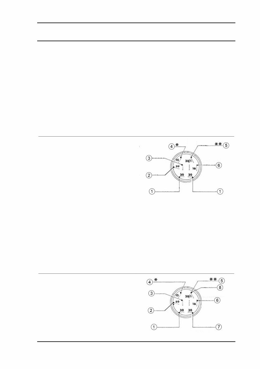
Maintenance guidelines RULES TO BE FOLLOWED IN THE EVENT OF INTERVENTION ON THE ELECTRIC SYSTEM - APE TM A) ESSENTIAL WARNINGS The check or in any case the intervention on the circuits of the devices for the electronic ignition can be done with relative ease by the electronic repairers of Service Station Workshops; it is essential, however, that they take observe the notices below, since, in case of failure to observe, they could irreparably damage the devices. All inspection operations of the system involving disconnection of cables (verification of the connections and devices that are part of the ignition circuit, therefore including the main key switch) must be made with the engine off: otherwise the control unit could be irreparably damaged. The ignition circuit works on AC, and obviously, must be definitely separated from that of DC In fact the latter, powered by the battery and dy- namotor, serves only for the service user groups (city lights, stop, horn, lights, headlight, etc.). KEY: 1 = Red (direct current) 2 = White (direct current) 3 = Grey - Red (direct current) 4 = Purple (alternating current engine stop) 5 = Black (ground) 6 = White - Red (direct current) * = Connection connected to the red cable of the condenser charging coil. ** = Connections with electronic ignition. If there is a connection of two circuits, i.e., if the ignition one was routed by the DC, there would be instantaneous deterioration of the control unit. It is therefore necessary and important that, in case of removal or disconnection of cables, particularly of those which depend on the main key switch and the control unit, during reassembly pay attention to correctly reconnect each cable to the APE TM Benzina General guidelines GEN - 7
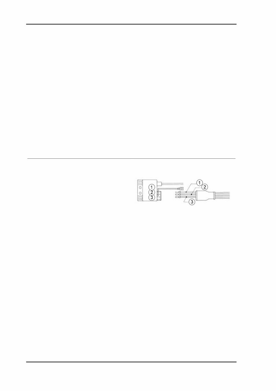
corresponding terminal; for this purpose it is al- ways advisable to consult the electrical circuit diagrams. KEY: 1 = Red (direct current) 2 = White (direct current) 3 = Grey - Red (direct current) 4 = Purple (alternating current engine stop) 5 = Black (ground) 6 = White - Red (direct current) 7 = Grey (direct current) 8 = Black * = Connection connected to the red cable of the condenser charging coil. ** = Connections with electronic ignition. For obvious reasons it is essential that, in case of replacement of one or more devices in the system (main switch, stator unit of the flywheel, control unit) during reassembly, a device is used that is similar to the existing one: if in fact similar devices were used, but not specific to the same ignition system, they would not work, risking irreparable damage to the control unit. KEY: 1 = White 2 = Red 3 = Green B) INSPECTIONS TO BE PERFORMED IN THE EVENT OF IGNITION IRREGULARITIES In the event of failure and abnormal operation of the ignition, whose causes are not detectable by a visual inspection, it is necessary first to replace the control unit with a corresponding, safely functional one. Remember that the disconnections and connections to replace the control unit must be performed when the engine is off. General guidelines APE TM Benzina GEN - 8
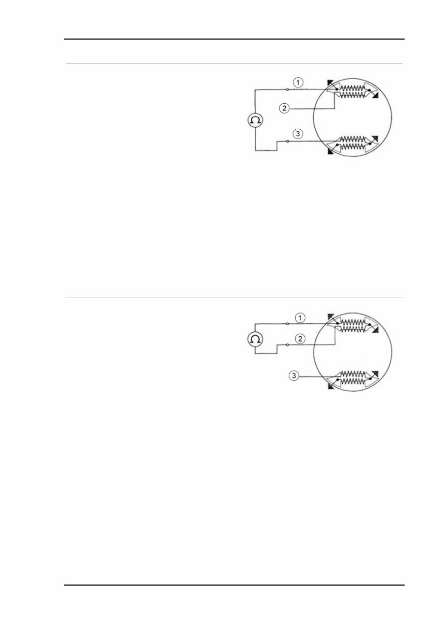
If replacing restores the ignition operation, the fault lies in the control unit, which obviously needs to be replaced. In the event that the failure persists, it is necessary to carry out checks on the alternator and on the stator components as follows: After a visual inspection of the connections, stator and couplings, measurements are carried out on the charging coil and the ignition coil using an Ohm meter, capable of detecting resistance from 1 to 1000 ohm, as follows: - Connect the instrument between the WHITE ca- ble and the RED cable; there must be continuity and ohmic value (430 to 480 ohm); KEY: 1) White 2) Red 3) Green - Connect the + terminal of the instrument with the WHITE cable and the - terminal of the instrument with the RED cable there must be continuity and ohmic value (7 to 9 ohm). KEY: 1) White 2) Red 3) Green If failures are detected in the inspections of the charging coil and ignition coil, proceed to replace the damaged parts. If there is no tool available to check the stator, when it is established that the ignition problem is not related to the power control unit nor to other visible causes (bad connections, damaged cables, dam- aged spark plug), proceed to replace the complete stator. In relation to what described in the preceding paragraphs we recommend, therefore, to include in the control tools an Ohm meter with the charac- teristics outlined above. C) IGNITION TIMING CHECK APE TM Benzina General guidelines GEN - 9
The timing check may be useful for example if the motor is not operating properly (start-up difficulties; decreased performance and power; difficult or irregular recovery speed etc.); if the failure does not depend on the carburetion, it may be caused by irregularities of the ignition timing. This possibility is, however, considered quite rare since, due to the characteristics of the ignition system, the timing adjustment remains unchanged over time; since the problem arises in most cases from ir- regular operation of the control unit, to be sure please follow the steps outlined on the side for verification of the aforementioned device. If however, after checking the carburetion and the control unit, the desired improvements are not ob- tained and there is doubt whether the anomalies are due to the ignition timing, proceed to check the latter, operating as follows:. 1) Insert, into the hole (1) a rod of Ø 5 mm.; run the engine manually until when the end of the rod, coming into correspondence with the other hole on the rotor, does not fit. In this condition the engine is in ignition advance position. 2) Make a mark with white paint on the fan cover, in correspondence with the flap of the flywheel bearing the reference for the timing. 3) Connect a stroboscopic lamp (type TECNOTEST 130/P or other similar) at ignition; the connection will be made directly on the spark plug or on the H.V. cable, etc. depending on the type of stroboscopic lamp available and the specific operating instructions. Then start the engine and bring it to about 4000-5000 rpm. 4) The engine will be properly timed to the lamp when the two marks are aligned, or at most, moved to within a tolerance range of 4° (i.e., within 2° to the right and 2° to the left of alignment position). 5) If the mark of the flywheel rotor is shifted compared to the crankcase more than the allowed tolerance (or other major irregularities appear during the check), replace the stator or the control unit. N.B. FOR VEHICLES OF NEXT PRODUCTION, THE FAN COVER WILL BE FITTED WITH A REFER- ENCE FOR TIMING, SO THE OPERATIONS DESCRIBED IN POINTS 1 AND 2 WILL NOT BE NECESSARY. RULES TO BE FOLLOWED IN THE EVENT OF INTERVENTION ON THE ELECTRIC SYSTEM - APE TM P703 FL2 A) ESSENTIAL WARNINGS The check or in any case the intervention on the circuits of the devices for the electronic ignition can be done with relative ease by the electronic repairers of Service Station Workshops; it is essential, however, that they take observe the notices below, since, in case of failure to observe, they could irreparably damage the devices. General guidelines APE TM Benzina GEN - 10
The 2012 Piaggio APE TM Benzina Service & Repair Manual is an essential guide for both the professional mechanic and the dedicated DIY enthusiast. It provides comprehensive coverage of the entire vehicle, ensuring that every repair or maintenance task can be performed with confidence.
Key features include:
Step-by-step instructions for accurate servicing and repairs
Highly detailed exploded pictures for clear understanding of the vehicle’s components
An in-depth explanation of topics such as:
General guidelines and characteristics
Special tools requirements
Maintenance procedures
Emission control system details
Troubleshooting techniques
Electrical system diagnostics
Engine and gear-box repair
Braking system, steering column, and suspensions
Tipper version specifics and chassis information
Pre-delivery checks
This manual is conveniently available in PDF format, making it accessible on Windows PCs, Macs, tablets, and smartphones. The digital format allows you to easily print selected sections or the entire manual as needed.
With instant download upon payment, you will have immediate access without any shipping delays. Payment methods accepted include all major credit/debit cards and PayPal.
If you require assistance finding a specific manual, our customer support team is ready to help. Simply contact us with the details you need, and we will do our best to locate it for you.
Join thousands of satisfied customers who have made this manual their trusted resource for vehicle maintenance and repair. Thank you for choosing the 2012 Piaggio APE TM Benzina Service & Repair Manual for your vehicle care needs.
Recently Viewed
5,521,897Happy Clients
2,594,462eManuals
1,120,453Trusted Sellers
15Years in Business
Price:
Actual Price:
2012 Piaggio APE TM Benzina Service & Repair Manual