1 General information and precautions The electrical system is of 12-volt negative earth type. Power for the lights and all electrical accessories is supplied by a lead/acid type battery, which is charged by the alternator. This Chapter covers repair and service procedures for the various electrical components not associated with engine. Information on the battery, alternator and starter motor can be found in Chapter 5. It should be noted that, before working on any component in the electrical system, the battery negative terminal should first be disconnected, to prevent the possibility of electrical short-circuits and/or fires. Whenever the occasion arises, carefully check the routing of the wiring harness, ensuring that it is correctly secured by the clips or ties provided so that it cannot chafe against other components. Carefully check points such as the clutch cable bracket, clutch housing and harness support bracket, the inlet manifold, the horn mounting bracket, the starter motor terminals, and the rear bumper and number plate lamp. If evidence is found of the harness having chafed against other components, repair the damage and ensure that the harness is secured or protected so that the problem cannot occur again. 2 Electrical fault-finding - general information Note: Refer to the precautions given in “Safety first!” (at the beginning of this manual) and to Section 1 of this Chapter before starting work. The following tests relate to testing of the main electrical circuits, and should not be used to test delicate electronic circuits (such as anti- lock braking systems), particularly where an electronic control module is used. A typical electrical circuit consists of an electrical component, any switches, relays, motors, fuses, fusible links or circuit breakers related to that component, and the wiring and connectors that link the component to both the battery and the chassis. To help to pinpoint a problem in an electrical circuit, wiring diagrams are included at the end of this Chapter. Before attempting to diagnose an electrical fault, first study the appropriate wiring diagram, to obtain a complete understanding of the components included in the particular circuit concerned. The possible sources of a fault can be narrowed down by noting whether other components related to the circuit are operating properly. If several components or circuits fail at one time, the problem is likely to be related to a shared fuse or earth connection. Electrical problems usually stem from simple causes, such as loose or corroded connections, a faulty earth connection, a blown fuse, a melted fusible link, or a faulty relay (refer to Section 3 for details of testing relays). Visually inspect the condition of all fuses, wires and connections in a problem circuit before testing the components. Use the wiring diagrams to determine which terminal connections will need to be checked, to pinpoint the trouble-spot. The basic tools required for electrical fault- finding include the following: a) a circuit tester or voltmeter (a 12-volt bulb with a set of test leads can also be used for certain tests). b) a self-powered test light (sometimes known as a continuity tester). c) an ohmmeter (to measure resistance). d) a battery. e) a set of test leads. f) a jumper wire, preferably with a circuit breaker or fuse incorporated, which can be used to bypass suspect wires or electrical components. Before attempting to locate a problem with test instruments, use the wiring diagram to determine where to make the connections. To find the source of an intermittent wiring fault (usually due to a poor or dirty connection, or damaged wiring insulation), a “wiggle” test can be performed on the wiring. This involves wiggling the wiring by hand, to see if the fault occurs as the wiring is moved. It should be possible to narrow down the source of the fault to a particular section of wiring. This method of testing can be used in conjunction with any of the tests described in the following sub-Sections. Apart from problems due to poor connections, two basic types of fault can occur in an electrical circuit - open-circuit, or short-circuit. Open-circuit faults are caused by a break somewhere in the circuit, which prevents current from flowing. An open-circuit fault will prevent a component from working, but will not cause the relevant circuit fuse to blow. Short-circuit faults are caused by a “short” somewhere in the circuit, which allows the current flowing in the circuit to “escape” along an alternative route, usually to earth. Short- circuit faults are normally caused by a breakdown in wiring insulation, which allows a feed wire to touch either another wire, or an earthed component such as the bodyshell. A short-circuit fault will normally cause the relevant circuit fuse to blow. Finding an open-circuit To check for an open-circuit, connect one lead of a circuit tester or voltmeter to either the negative battery terminal or a known good earth. Connect the other lead to a connector in the circuit being tested, preferably nearest to the battery or fuse. Switch on the circuit, remembering that some circuits are live only when the ignition switch is moved to a particular position. If voltage is present (indicated either by the tester bulb lighting or a voltmeter reading, as applicable), this means that the section of the circuit between the relevant connector and the battery is problem-free. Continue to check the remainder of the circuit in the same fashion. When a point is reached at which no voltage is present, the problem must lie between that point and the previous test point with voltage. Most problems can be traced to a broken, corroded or loose connection. Finding a short-circuit To check for a short-circuit, first disconnect the load(s) from the circuit (loads are the components that draw current from a circuit, such as bulbs, motors, heating elements, etc.). Remove the relevant fuse from the circuit, and connect a circuit tester or voltmeter to the fuse connections. Switch on the circuit, remembering that some circuits are live only when the ignition switch is moved to a particular position. If voltage is present (indicated either by the tester bulb lighting or a voltmeter reading, as applicable), this means that there is a short- circuit. If no voltage is present, but the fuse still blows with the load(s) connected, this indicates an internal fault in the load(s). Finding an earth fault The battery negative terminal is connected to “earth” (the metal of the engine/transmission and the car body), and most systems are wired so that they only receive a positive feed. The current returning through the metal of the car body. This means that the component mounting and the body form part of that circuit. Loose or corroded mountings can therefore cause a range of electrical faults, ranging from total failure of a circuit, to a puzzling partial fault. In particular, lights may shine dimly (especially when another circuit sharing the same earth point is in operation). Motors (e.g. wiper motors or the radiator cooling fan motor) may run slowly, and the operation of one circuit may have an affect on another. Note that on many vehicles, earth straps are used between certain components, such as the engine/transmission and the body, usually where there is no metal- 12•2 Body electrical systems Warning: Before carrying out any work on the electrical system, read through the precautions given in “Safety first!” at the beginning of this manual, and in Chapter 5. Caution: If the radio/cassette player fitted to the vehicle is one with an anti-theft security code, as the standard unit is, refer to “Radio/cassette player anti-theft system - precaution” in the Reference Section of this manual before disconnecting the battery.
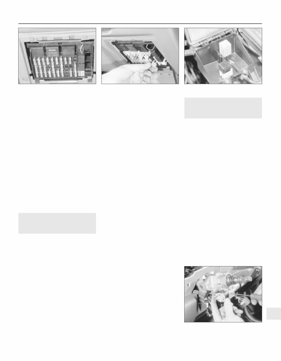
to-metal contact between components, due to flexible rubber mountings, etc. To check whether a component is properly earthed, disconnect the battery, and connect one lead of an ohmmeter to a known good earth point. Connect the other lead to the wire or earth connection being tested. The resistance reading should be zero; if not, check the connection as follows. If an earth connection is thought to be faulty, dismantle the connection, and clean back to bare metal both the bodyshell and the wire terminal or the component earth connection mating surface. Be careful to remove all traces of dirt and corrosion, then use a knife to trim away any paint, so that a clean metal-to-metal joint is made. On reassembly, tighten the joint fasteners securely; if a wire terminal is being refitted, use serrated washers between the terminal and the bodyshell, to ensure a clean and secure connection. When the connection is remade, prevent the onset of corrosion in the future by applying a coat of petroleum jelly or silicone-based grease. 3 Fuses and relays - general Fuses 1 Fuses are designed to break a circuit when a predetermined current is reached, to protect the components and wiring which could be damaged by excessive current flow. Any excessive current flow will be due to a fault in the circuit, usually a short-circuit (Section 2). 2 The main fuses and relays are located in a panel at the lower right-hand side of the facia, under a hinged cover (see illustration). 3 The circuits protected by the various fuses and relays are marked on the inside of the panel cover. 4 A blown fuse can be recognised from its melted or broken wire. 5 To remove a fuse, first ensure that the relevant circuit is switched off. Then open the cover and pull the relevant fuse or relay from the panel (see illustration). If desired, the lower end of the panel can be tilted forwards, after releasing the retaining clips to improve access. 6 Before renewing a blown fuse, trace and rectify the cause, and always use a fuse of the correct rating. Never substitute a fuse of a higher rating, or make temporary repairs using wire or metal foil, as more serious damage or even fire could result. 7 Spare fuses are provided in the blank terminal positions in the fusebox. 8 Note that the fuses are colour-coded, see Specifications. Refer to the wiring diagrams for details of the fuse ratings and the circuits protected. Relays 9 A relay is an electrically operated switch, which is used for the following reasons: a) A relay can switch a heavy current remotely from the circuit in which the current is flowing, allowing the use of lighter-gauge wiring and switch contacts. b) A relay can receive more than one control input, unlike a mechanical switch. c) A relay can have a timer function - for example, the intermittent wiper relay. 10 Most of the relays are located at the rear of the main fusebox (remove the securing screws and pull the fusebox forwards to improve access). The rear wiper motor relay is located in the tailgate, behind the tailgate trim panel. On some models, additional engine- related relays are located in the relay box mounted on the left-hand side of the engine compartment. 11 On certain models, additional relays are located in a box at the left-hand rear of the engine compartment (see illustration). 12 If a circuit or system controlled by a relay develops a fault, and the relay is suspect, operate the system. If the relay is functioning, it should be possible to hear it “click” as it is energised. If this is the case, the fault lies with the components or wiring of the system. If the relay is not being energised, then either the relay is not receiving a main supply or a switching voltage, or the relay itself is faulty. Testing is by the substitution of a known good unit, but be careful - while some relays are identical in appearance and in operation, others look similar but perform different functions. 13 To remove a relay, first ensure that the relevant circuit is switched off. The relay can then simply be pulled out from the socket, and pushed back into position. 4 Ignition switch and lock cylinder - removal and refitting 3 Removal 1 Disconnect the battery negative lead. 2 Turn the steering wheel as necessary to expose the two front steering column shroud securing screws, which are covered by plastic caps. Prise out the caps and remove the screws. 3 Remove the three securing screws from the underside of the lower column shroud, then remove both the upper and lower shrouds. 4 To remove the lock cylinder, insert the ignition key and turn it to position “II”. 5 Insert a thin rod into the hole in the lock housing, then press the rod to release the detent spring, and pull out the lock cylinder using the key. 6 The ignition switch is secured to the steering lock housing by two grub screws. Disconnect the wiring plug, and remove the screws to extract the switch (see illustration). Removal of the steering wheel, may aid removal. Refer to Chapter 10 or Section 57, as applicable. It is recommended that the switch and the lock cylinder are not both removed at the same time, so that their mutual alignment is not lost. Refitting 7 Refitting is a reversal of removal. Body electrical systems 12•3 3.11 Relays in engine compartment box - 2.0 litre SRi model shown 4.6 Removing an ignition switch securing screw 3.5 Removing a fuse - 2.0 litre model shown 3.2 Main fuses and relays in facia panel - 2.0 litre SRi model shown 12
5 Direction indicator/lighting switch - removal and refitting 2 Removal 1 Disconnect the battery negative lead. 2 Turn the steering wheel as necessary to expose the two front steering column shroud securing screws, which are covered by plastic caps. Prise out the caps and remove the screws. 3 Remove the three securing screws from the underside of the lower column shroud, then remove both the upper and lower shrouds. 4 Disconnect the wiring plug from the switch. 5 Depress the switch retaining clip, and withdraw the switch from the housing. Refitting 6 Refitting is a reversal of removal. 6 Wash/wipe switch - removal and refitting 2 Proceed as described in Section 5. 7 Facia panel switches - removal and refitting 2 1 Disconnect the battery negative lead. Lighting switch Removal 2 Turn the switch to the “dipped beam on” position, then insert a small screwdriver or rod through the hole in the bottom of the switch knob to depress the knob retaining clip. Pull the knob from the switch (see illustration). 3 Press the two now-exposed switch securing clips towards the switch spindle, then pull the switch from the facia and disconnect the wiring plug (see illustrations). 4 Note that the switch assembly cannot be dismantled, and if any part of the switch is faulty, the complete assembly must be renewed. Refitting 5 Refitting is a reversal of removal. Push-button switches Removal 6 First check beneath the switch, if there is a small hole in the facia, insert a slim screwdriver or metal rod into it. Release the switch retaining spring clip by pressing it upwards against the switch, then remove the switch and disconnect its wiring. If there is no hole, remove the switch by prising it out of the facia using a small screwdriver. Lever gently under the switch’s lower edge (use adhesive tape or a piece of card to protect the facia’s finish). Disconnect the switch wiring plug and withdraw the switch (see illustration). Refitting 7 Refitting is a reversal of removal. Headlamp aim adjustment switch 8 The procedure is as described for push- button switches. Hazard warning switch Removal 9 Using a screwdriver, carefully prise the cap from the switch (see illustration). 10 Using a screwdriver with a piece of card under the blade to avoid damage to the facia trim, prise the ventilation nozzle from the facia. 11 Prise the switch from the facia and disconnect the wiring (see illustration). Refitting 12 Refitting is a reversal of removal. Heater blower motor switch Removal 13 Remove the heater control panel, as described in Chapter 11. 14 Disconnect the wiring plug from the switch, if not already done. 15 Prise the switch out from the rear of the heater control panel. Refitting 16 Refitting is a reversal of removal, but refer to Chapter 11, when refitting the heater control panel. 12•4 Body electrical systems 7.2 Using a thin rod to depress the lightning switch knob retaining clip 7.3B . . . then pull the switch from the facia 7.11 Withdrawing the hazard warning flasher switch from the facia 7.9 Prising the cap from the hazard warning flasher switch 7.6 Prising a push-button switch from the facia 7.3A Press the switch securing clips towards the switch spindle . . .
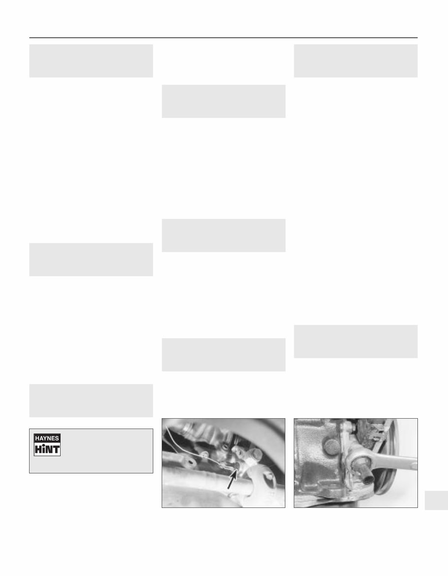
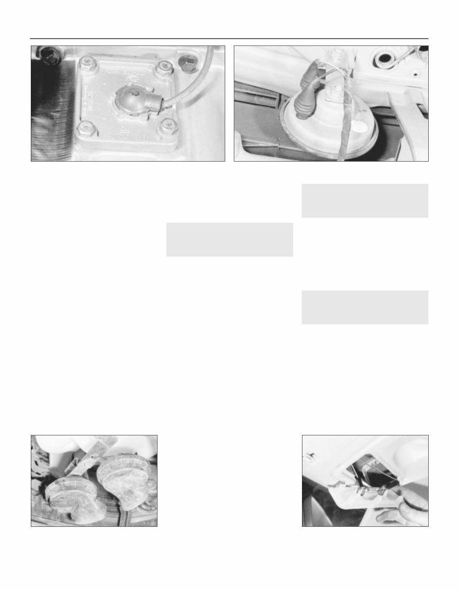
8 Electric door mirror switch - removal and refitting 2 Removal 1 Disconnect the battery negative lead. 2 Prise the plastic surround from the door interior handle. 3 Free the trim panel from the top edge of the door by releasing the securing clips. This can be done using a screwdriver, but it is preferable to use a forked tool, to minimise the possibility of damage to the trim panel and the clips. 4 Note the position of the mirror switch wiring connector in the bracket at the top of the door, then separate the two halves of the connector. 5 Prise the switch from the door trim panel, and feed the wiring through the panel. Refitting 6 Refitting is a reversal of removal, but ensure that the wiring is correctly routed, so as not to foul the door interior handle mechanism. 9 Sunroof operating switch - removal and refitting 2 Removal 1 Disconnect the battery negative lead. 2 Prise the courtesy lamp from the roof trim panel, and disconnect the wiring. 3 Remove the two trim panel securing screws, and withdraw the trim panel from the roof, disconnecting the wiring from the sunroof operating switch. 4 Release the securing clips, then pull the switch from the rear face of the trim panel. Refitting 5 Refitting is a reversal of removal. 10 Courtesy lamp switch - removal and refitting 2 Removal 1 Disconnect the battery negative lead. 2 Open the door and remove the switch securing screw. 3 Withdraw the switch from the door pillar, and pull the wiring out sufficiently to prevent it from springing back into the pillar. 4 Disconnect the wiring and remove the switch. Refitting 5 Refitting is a reversal of removal. 11 Luggage compartment lamp switch - removal and refitting 2 Removal 1 Disconnect the battery negative lead. 2 Open the boot lid or tailgate, as applicable, and remove the switch securing screw. 3 Withdraw the switch from the body panel, and pull the wiring out sufficiently to prevent it from springing back into the body. 4 Disconnect the wiring and remove the switch. Refitting 5 Refitting is a reversal of removal. 12 Brake lamp switch - removal and refitting 2 Removal 1 Disconnect the battery negative lead. 2 Remove the lower trim panel from the driver’s footwell. 3 Disconnect the wiring plug from the brake lamp switch, then twist the switch anti-clockwise and remove it from its bracket. Refitting 4 Refitting is a reversal of removal. 13 Handbrake “on” warning lamp switch - removal and refitting 3 For access to the switch, the handbrake lever must be removed. Removal and refitting of the switch is described as part of the handbrake lever removal and refitting procedure, in Chapter 9. 14 Oil pressure warning lamp switch - removal and refitting 3 Removal 1 Disconnect the battery negative lead. 2 The switch is screwed into the oil pump, on the inlet manifold side of the engine. On 1.4 and 1.6 litre (except C16 NZ2), models the switch projects at right-angles to the crankshaft axis, while on C16 NZ2, 1.8 and 2.0 litre models it is parallel to the crankshaft (see illustration). 3 In most cases the switch can be reached quite easily from above. However, on some models access will be easier if the front of the vehicle is jacked up and supported on axle stands (see “Jacking and Vehicle Support”) (ensure that the handbrake is securely applied) and the front right-hand roadwheel is removed. 4 Disconnect the switch wire and use a spanner to unscrew the switch (see illustration). As you withdraw the switch, swiftly plug the hole in the oil pump to minimise the loss of oil and to prevent the entry of dirt. Refitting 5 Refitting is the reverse of the removal procedure; tighten the switch securely but do not overtighten it, reconnect its wire, then check and if necessary top-up the oil level, as described in Chapter 1. Wash off any spilt oil and check for leaks when the engine is restarted. 15 Cigarette lighter - removal and refitting 2 Removal 1 Disconnect the battery negative lead. 2 Slide the ashtray/cigarette lighter assembly from the facia, then disconnect the wiring and slide the illumination bulb from the cigarette lighter. Body electrical systems 12•5 14.4 Unscrewing the oil pressure warning lamp switch - SOHC model (engine removed) 14.2 Oil pressure warning lamp switch (arrowed) viewed from underneath vehicle - SOHC model 12 Tape the wiring to the door pillar, to prevent if falling back into the door pillar. Alternatively, tie a piece of string to the wiring to retrieve it.
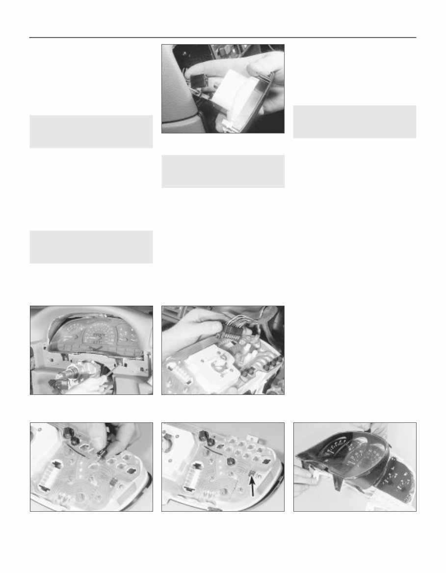
3 To remove the cigarette lighter assembly, simply pull it from the illumination ring assembly. If desired, the illumination ring assembly can be removed, by pulling it from the housing after depressing the retaining clips. Refitting 4 Refitting is a reversal of removal. 16 Clock - removal and refitting 2 Removal 1 Disconnect the battery negative lead. 2 Using a thin-bladed screwdriver, carefully prise the clock from the facia panel. 3 Disconnect the wiring plugs and withdraw the clock (see illustration). Refitting 4 Refitting is a reversal of removal. 17 Heated front seats - general 2 Heating pads are fitted to the front seats of some models. Before attempting to remove a seat so equipped, disconnect the battery and the leads from the heating pad. 18 Instrument panel - removal and refitting 3 Removal 1 Disconnect the battery negative lead. 2 Remove the steering wheel, (Chapter 10). 3 Remove the steering column shrouds, and the instrument panel upper and lower trim panels, (Chapter 11). 4 Remove the single upper, and two lower, instrument panel securing screws (see illustration). 5 Carefully withdraw the instrument panel, and disconnect the speedometer cable and the two wiring plugs. Note that the speedometer cable is retained by a clip, which must be pressed towards the speedometer to release the cable (see illustration). 6 If desired, the instrument panel can be dismantled, with reference to Section 19. Refitting 7 Refitting is a reversal of removal, but ensure that the speedometer cable is not kinked or twisted between the instrument panel and the bulkhead as the panel is refitted. 19 Instrument panel components - removal and refitting 3 1 With the instrument panel removed, as described in Section 18, continue as follows. Panel illumination and warning lamp bulbs Removal 2 Twist the relevant bulbholder clockwise, and withdraw it from the printed circuit board on the rear of the instrument panel (see illustration). 3 The bulbs are integral with the bulbholders, and must be renewed as a unit. Refitting 4 Refitting is a reversal of removal. Voltage stabiliser Removal 5 Remove the single securing screw from the rear of the instrument panel, then pull the voltage stabiliser from the contacts on the printed circuit board (see illustration). Refitting 6 Refitting is a reversal of removal. Fuel and temperature gauges - “low series” models Removal 7 Pull the trip meter reset pin from the front of the panel. 8 Release the two retaining clips at the top of the panel, and remove the panel shroud (see illustration). 9 Unscrew the two securing nuts, and withdraw the relevant gauge through the front of the instrument panel. 12•6 Body electrical systems 16.3 Disconnecting the wiring plugs from the clock 18.5 Disconnecting an instrument panel wiring plug. Note speedometer cable retaining clip (arrowed) 19.8 Removing the instrument panel shroud 19.5 Instrument panel voltage stabiliser (arrowed) 19.2 Withdrawing an instrument panel illumination lamp bulb 18.4 Unscrewing a lower instrument panel securing screw
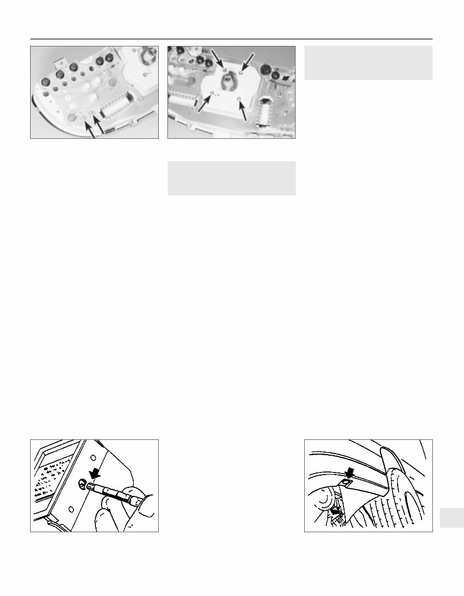
Refitting 10 Refitting is a reversal of removal. Fuel and temperature gauge assembly - “high series” models 11 The procedure is as described in paragraphs 7 to 10 inclusive, except that the gauge assembly is secured by four nuts. Tachometer 12 The procedure is as described in paragraphs 7 to 10 inclusive except that the tachometer is secured by three nuts (see illustration). Speedometer Removal 13 Proceed as described in paragraphs 7 and 8. 14 Extract the four securing screws from the rear of the panel (see illustration). Refitting 15 Refitting is a reversal of removal. Printed circuit board Removal 16 Remove all bulbs and instruments, and the voltage stabiliser, as described previously in this Section. 17 Carefully peel the printed circuit board from the instrument panel. Refitting 18 Refitting is a reversal of removal, but ensure that the printed circuit board is seated correctly on the rear of the instrument panel. 20 Trip computer components - removal and refitting 2 1 Disconnect the battery lead. Display module Removal 2 Using a thin-bladed screwdriver, carefully prise the module from the facia panel. 3 Disconnect the wiring plug and withdraw the module. Refitting 4 Refitting is a reversal of removal. Display module illumination bulb Removal 5 Remove the display module, as described previously in this Section. 6 Using a length of rubber sleeving of similar diameter, or an alternator tool, extract the bulb by inserting the tool through the hole in the side of the display module (see illustration). Refitting 7 Refitting is a reversal of removal. Operating switch Removal 8 Remove the rear section of the centre console, as described in Chapter 11. 9 Release the wiring plug from the switch using a screwdriver. 10 Lift the switch, then pull it down and out from the centre console. Refitting 11 Refitting is a reversal of removal. Outside air temperature sensor Removal 12 The sensor is located at the left-hand end of the front bumper (see illustration). 13 Prise the cover cap from the bumper, then unclip the sensor, and disconnect the wiring plug. Refitting 14 Refitting is a reversal of removal. 21 Check control system components - removal and refitting 3 1 Disconnect the battery negative lead. Warning lamp bulbs 2 The warning lamp bulbs are located in the instrument panel, and removal and refitting are described in Section 19. Control module Removal 3 The control module is located behind the passenger side of the facia, above the glovebox. 4 Remove the glovebox assembly, as described in Chapter 11. 5 Disconnect the control module wiring plug, then release the control module from its mounting and withdraw the unit. Refitting 6 Refitting is a reversal of removal. Coolant level sensor Removal 7 The coolant level sensor is integral with the coolant expansion tank cap. 8 Disconnect the wiring from the top of the cap, then unscrew the cap and withdraw it from the expansion tank. 9 If faulty, the complete cap assembly must be renewed. Refitting 10 Refitting is a reversal of removal. Washer fluid level sensor Removal 11 The sensor is mounted in the side of the fluid reservoir. 12 Disconnect the wiring from the sensor, then unscrew the sensor from the fluid reservoir. If the fluid level is above the level of the sensor, be prepared for fluid spillage. Refitting 13 Refitting is a reversal of removal. Body electrical systems 12•7 20.6 Removing the trip computer display module illumination bulb 20.12 Trip computer outside air temperature sensor location (arrowed) 19.14 Speedometer securing screws (arrowed) 19.12 Tachometer securing nuts (arrowed) 12
Brake fluid level sensor 14 The procedure is as described for the coolant level sensor in paragraphs 7 to 10 inclusive. Engine oil level sensor Removal 15 Apply the handbrake, jack up the front of the vehicle, and support securely on axle stands (see “Jacking and Vehicle Support”) positioned under the body side members. 16 On DOHC models, remove the engine undershield, as described in Chapter 11. 17 Disconnect the sensor wiring plug. 18 Unscrew the three or four sensor securing screws, as applicable, and withdraw the sensor, manipulating the float through the hole in the sump (see illustration). Recover the sealing ring. Be prepared for some oil spillage. 19 Examine the condition of the sealing ring, and renew if necessary. Refitting 20 Refitting is a reversal of removal. On completion, check, and if necessary top-up, the engine oil level. Bulb failure sensor Removal 21 The bulb failure sensor is mounted behind the fuse/relay panel in the facia. 22 Release the retaining clips from the lower end of the fuse/relay panel, and tilt it forwards. 23 Reach up behind the fuse/relay panel, and pull the sensor from its socket. Refitting 24 Refitting is a reversal of removal. 22 Horn(s) - removal and refitting 2 1 On models with a single horn, the horn is located in front of the radiator. On models with twin horns, the horns are located beneath the washer fluid reservoir, at the left-hand end of the front bumper. Single horn Removal 2 Disconnect the battery negative lead. 3 Remove the radiator grille panel, with reference to Chapter 11. 4 Disconnect the wiring from the rear of the horn. 5 Reach up behind the mounting bracket, and unscrew the single nut securing the horn to the bracket (see illustration). Withdraw the horn. Refitting 6 Refitting is a reversal of removal. Twin horns Removal 7 Disconnect the battery negative lead. 8 Apply the handbrake, then jack up the front of the vehicle, and support securely on axle stands (see “Jacking and Vehicle Support”) positioned under the body side members. 9 Remove the securing screws, and withdraw the plastic cover (where fitted) from the bumper/front wing to expose the horns. 10 Remove the bolt securing the horn mounting bracket to the bracket below the washer fluid reservoir (see illustration). 11 Withdraw the horns and disconnect the wiring. 12 If desired, the horns can be unbolted from the bracket. Refitting 13 Refitting is a reversal of removal. 23 Interior lamps - removal and refitting 2 Removal 1 Disconnect the battery negative lead. 2 Using a thin-bladed screwdriver, prise the lamp from its location and disconnect the wiring (see illustration). Refitting 3 Refitting is a reversal of removal. 24 Interior lamp bulbs - renewal 1 1 Disconnect the battery negative lead. Courtesy lamp Note: Some later models are fitted with courtesy lamps for the rear seat passengers, as well as front. Removal 2 Using a thin-bladed screwdriver, prise the lamp from its location and disconnect the wiring. 3 On models fitted with a courtesy lamp with integral map reading lamps, the lens must be levered from the housing for access to the bulbs. 12•8 Body electrical systems 21.18 Engine oil level sensor - DOHC model 22.10 Horn mounting bracket securing bolt (arrowed) - twin horned model 23.2 Withdrawing the courtesy lamp 22.5 Horn viewed from behind with radiator removed - single horned model
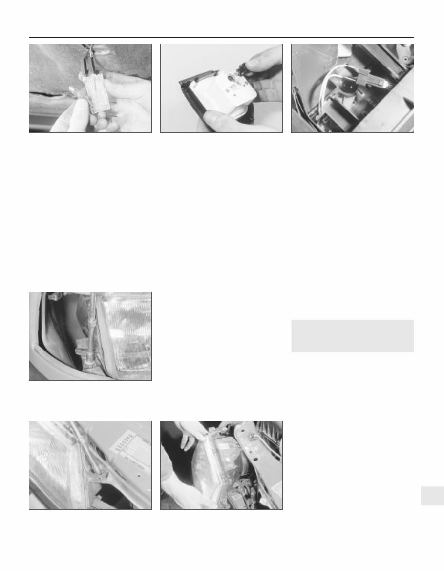
4 Remove the courtesy lamp bulbs by carefully prising it from its location using a thin-bladed screwdriver. Where applicable, the map reading lamp bulbs are a push fit in the bulbholders. Refitting 5 Refitting is a reversal of removal. Glovebox lamp Removal 6 Using a thin-bladed screwdriver, prise the lamp from its location and disconnect the wiring. 7 Carefully prise the bulb from the lamp. Refitting 8 Refitting is a reversal of removal. Luggage compartment, underbonnet and kerb lamps Removal 9 Using a thin-bladed screwdriver, prise the lamp from its location; disconnect the wiring. 10 Carefully prise the bulb from the lamp (see illustration). Refitting 11 Refitting is a reversal of removal Cigarette lighter illumination lamp Removal 12 Slide the ashtray/cigarette lighter assembly from the facia, then disconnect the wiring and pull the bulbholder from the rear of the cigarette lighter housing. 13 The bulb is a push fit in the bulbholder. Refitting 14 Refitting is a reversal of removal. Clock illumination lamp 15 Remove the clock, (Section 16). 16 Twist the bulbholder and pull it from the rear of the clock (see illustration). 17 The bulb is a push fit in the bulbholder. Trip computer display module illumination lamp 18 Refer to Section 20. Heater control panel illumination lamp Removal 19 Remove the heater control panel, as described in Chapter 11. 20 Pull the bulbholder from the rear of the control panel (see illustration). 21 The bulb is a push fit in the bulbholder. Refitting 22 Refitting is a reversal of removal. Facia panel switch illumination lamp 23 If a bulb fails in one of the facia panel switches, the complete switch assembly must be renewed, as described in Section 7, as no individual spare parts are available. Vanity mirror illumination lamp Removal 24 Lower the sunvisor and, using a thin-bladed screwdriver, prise out the mirror and diffuser assembly. Pull the bulb(s) from the spring contacts. Refitting 25 Refitting is a reversal of removal. 25 Headlamp unit - removal and refitting 2 Removal 1 Remove the radiator grille panel, as described in Chapter 11. 2 Remove the front indicator lamp unit, as described in Section 29. 3 Remove the cover from the rear of the headlamp unit, and disconnect the wiring plugs from the bulbs. 4 If applicable, disconnect the wiring plug from the headlamp aim adjustment motor. 5 Remove the three securing screws, and withdraw the headlamp unit (see illustrations). Feed the wiring through the headlamp casing as it is removed. 6 If required, the headlamp lens can be removed by releasing the spring clips around its edge. Refitting 7 Refitting is a reversal of removal. 8 On completion, have the headlamp alignment checked, with reference to Section 27. Body electrical systems 12•9 24.20 Heater control panel illumination lamp bulbholder withdrawn 25.5C Withdrawing a headlamp unit 25.5B Unscrewing an upper headlamp securing screw 25.5A Unscrewing the lower headlamp securing screw 24.16 Removing the clock illumination lamp bulbholder 24.10 Removing the underbonnet lamp bulb 12
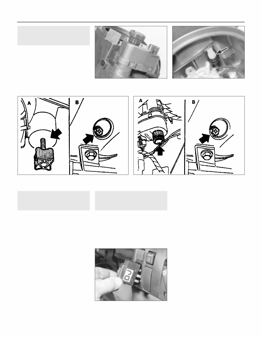
27 Headlamps - alignment 2 1 Correct alignment of the headlamp beams is most important, not only to ensure good vision for the driver, but also to protect other drivers from being dazzled. 2 Accurate alignment should be carried out using optical beam setting equipment. 3 In an emergency, adjustments may be made by turning the adjustment screws shown (see illustrations). If an adjustment is made, the alignment should be checked using beam setting equipment at the earliest opportunity. 4 All 1992-on models are fitted with the headlamp aim adjustment system, operated through the facia-mounted switch (see illustration). a) Position ‘0’, is for correct alignment if just the driving seat is occupied. b) Position ‘1’, if all seats are occupied. c) Position ‘2’, if all seats occupied and luggage. d) Position ‘3’, for just driver and luggage. 28 Headlamp dim-dip system - general, removal and refitting 3 General 1 The system (where fitted) is governed by the dim-dip control unit mounted either behind and above the glovebox (early models), or behind the main fuse panel (later models). 2 The control unit uses the oil pressure warning lamp circuit to ensure that, when the engine is running and the sidelamps are switched on, reduced current is fed to the headlamp dipped-beam circuits. This lights the headlamps with approximately one-sixth of their normal power so that the vehicle cannot be driven using sidelamps alone. 3 To locate the dim-dip control unit, open the main fuse panel covering flap and unclip it from its bottom and top mountings (Section 3). Then use a torch to see whether the unit is fastened to the plastic bracket behind the facia and fuse panel. The unit is usually rectangular, of black plastic, and can be identified by the colours of the five wires leading to it (see applicable wiring diagram). Removal 4 If the unit can be seen, remove the driver’s side lower facia and footwell trim panels (Chapter 11), then unscrew the four retaining screws and lower the plastic bracket until the control unit can be detached. 5 If the unit cannot be seen, remove the glovebox assembly (Chapter 11). The unit will be fastened to the underside of the facia top surface. Refitting 6 Refitting is the reverse of the removal procedure. 26 Headlamp aim adjustment motor - removal and refitting 3 Removal 1 Remove the headlamp, (Section 25). 2 Twist the motor clockwise to release it from the headlamp, then carefully disconnect the motor from the balljoint (see illustrations). Refitting 3 Refitting is a reversal of removal, but ensure that the motor is correctly engaged with the balljoint. 12•10 Body electrical systems 26.2A Headlamp aim adjustment motor (headlamp removed) 27.4 The headlamp aim adjustment switch - 1992-on models 27.3B Headlamp alignment adjustment screws - models with electric aim adjustment A Vertical adjustment screw B Horizontal adjustment screw 27.3A Headlamp alignment adjustment screws - models without electric aim adjustment A Vertical adjustment screw B Horizontal adjustment screw 26.2B Headlamp aim adjuster balljoint (arrowed)
Introducing the 1988-1995 Opel Vectra A Service & Repair Manual, the definitive guide for maintaining and repairing your Opel Vectra A. Whether you are a keen car enthusiast or a professional mechanic, this manual is designed to be your trusted companion in keeping your vehicle in peak condition.
Offering detailed step-by-step instructions, clear diagrams, and helpful illustrations, this comprehensive manual covers every aspect of servicing and repairing Opel Vectra A models produced between 1988 and 1995. From routine maintenance tasks to more complex repair procedures, every detail is explained to help you tackle challenges with confidence.
Key features of the 1988-1995 Opel Vectra A Service & Repair Manual include:
Complete coverage of all Opel Vectra A models built from 1988 to 1995
Detailed procedures for routine maintenance tasks such as oil changes, filter replacements, and fluid checks
Comprehensive troubleshooting guides for diagnosing and resolving common issues
Step-by-step repair instructions for advanced repairs including engine overhauls, transmission repairs, and electrical system troubleshooting
Clear, concise diagrams and illustrations that simplify complex procedures
Expert insights and tips from experienced professionals in Opel vehicle repair
Don't let mechanical issues stop you from enjoying your Opel Vectra A. With the 1988-1995 Opel Vectra A Service & Repair Manual, you will have all the essential information and guidance you need to ensure your vehicle remains reliable and efficient for years to come.