ACC-1 ENGINE C D E F G H I J K L M SECTION ACC A ACC N O P CONTENTS ACCELERATOR CONTROL SYSTEM PRECAUTION .............................................. 2 PRECAUTIONS .................................................. 2 FOR USA AND CANADA ........................................... 2 FOR USA AND CANADA : Precaution for Supple- mental Restraint System (SRS) "AIR BAG" and "SEAT BELT PRE-TENSIONER" ............................. 2 FOR MEXICO ............................................................. 2 FOR MEXICO : Precaution for Supplemental Re- straint System (SRS) "AIR BAG" and "SEAT BELT PRE-TENSIONER" .................................................. 2 REMOVAL AND INSTALLATION ............... 4 ACCELERATOR CONTROL SYSTEM .............. 4 Exploded View ......................................................... 4 Removal and Installation ......................................... 4 Inspection ................................................................ 4 Revision: 2010 October 2011 370Z
ACC-2 < PRECAUTION > PRECAUTIONS PRECAUTION PRECAUTIONS FOR USA AND CANADA FOR USA AND CANADA : Precaution for Supplemental Restraint System (SRS) "AIR BAG" and "SEAT BELT PRE-TENSIONER" INFOID:0000000006350765 The Supplemental Restraint System such as “AIR BAG” and “SEAT BELT PRE-TENSIONER”, used along with a front seat belt, helps to reduce the risk or severity of injury to the driver and front passenger for certain types of collision. This system includes seat belt switch inputs and dual stage front air bag modules. The SRS system uses the seat belt switches to determine the front air bag deployment, and may only deploy one front air bag, depending on the severity of a collision and whether the front occupants are belted or unbelted. Information necessary to service the system safely is included in the “SRS AIR BAG” and “SEAT BELT” of this Service Manual. WARNING: • To avoid rendering the SRS inoperative, which could increase the risk of personal injury or death in the event of a collision that would result in air bag inflation, all maintenance must be performed by an authorized NISSAN/INFINITI dealer. • Improper maintenance, including incorrect removal and installation of the SRS, can lead to personal injury caused by unintentional activation of the system. For removal of Spiral Cable and Air Bag Module, see “SRS AIR BAG”. • Never use electrical test equipment on any circuit related to the SRS unless instructed to in this Ser- vice Manual. SRS wiring harnesses can be identified by yellow and/or orange harnesses or harness connectors. PRECAUTIONS WHEN USING POWER TOOLS (AIR OR ELECTRIC) AND HAMMERS WARNING: • When working near the Air Bag Diagnosis Sensor Unit or other Air Bag System sensors with the ignition ON or engine running, never use air or electric power tools or strike near the sensor(s) with a hammer. Heavy vibration could activate the sensor(s) and deploy the air bag(s), possibly causing serious injury. • When using air or electric power tools or hammers, always switch the ignition OFF, disconnect the battery, and wait at least 3 minutes before performing any service. FOR MEXICO FOR MEXICO : Precaution for Supplemental Restraint System (SRS) "AIR BAG" and "SEAT BELT PRE-TENSIONER" INFOID:0000000006350766 The Supplemental Restraint System such as “AIR BAG” and “SEAT BELT PRE-TENSIONER”, used along with a front seat belt, helps to reduce the risk or severity of injury to the driver and front passenger for certain types of collision. Information necessary to service the system safely is included in the “SRS AIR BAG” and “SEAT BELT” of this Service Manual. WARNING: • To avoid rendering the SRS inoperative, which could increase the risk of personal injury or death in the event of a collision which would result in air bag inflation, all maintenance must be performed by an authorized NISSAN/INFINITI dealer. • Improper maintenance, including incorrect removal and installation of the SRS, can lead to personal injury caused by unintentional activation of the system. For removal of Spiral Cable and Air Bag Module, see “SRS AIR BAG”. • Never use electrical test equipment on any circuit related to the SRS unless instructed to in this Ser- vice Manual. SRS wiring harnesses can be identified by yellow and/or orange harnesses or harness connectors. PRECAUTIONS WHEN USING POWER TOOLS (AIR OR ELECTRIC) AND HAMMERS WARNING: • When working near the Air Bag Diagnosis Sensor Unit or other Air Bag System sensors with the ignition ON or engine running, never use air or electric power tools or strike near the sensor(s) with Revision: 2010 October 2011 370Z
PRECAUTIONS ACC-3 < PRECAUTION > C D E F G H I J K L M A ACC N P O a hammer. Heavy vibration could activate the sensor(s) and deploy the air bag(s), possibly causing serious injury. • When using air or electric power tools or hammers, always switch the ignition OFF, disconnect the battery, and wait at least 3 minutes before performing any service. Revision: 2010 October 2011 370Z
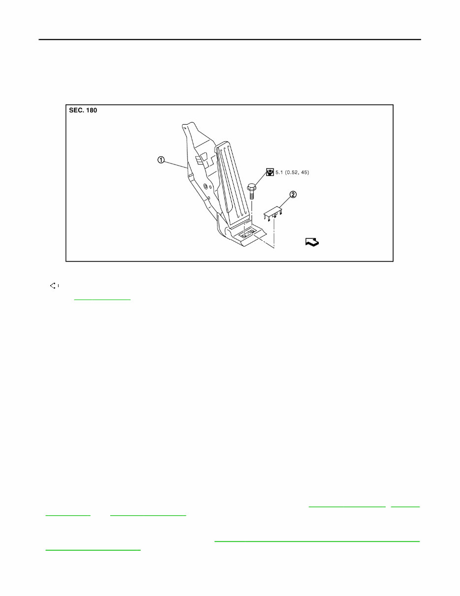
ACC-4 < REMOVAL AND INSTALLATION > ACCELERATOR CONTROL SYSTEM REMOVAL AND INSTALLATION ACCELERATOR CONTROL SYSTEM Exploded View INFOID:0000000006350767 Removal and Installation INFOID:0000000006350768 REMOVAL 1. Remove the bolt cap and the inside mounting bolt. 2. Remove accelerator pedal assembly. 3. Disconnect accelerator pedal position sensor harness connector. CAUTION: • Never disassemble accelerator lever. Never remove accelerator pedal position sensor from accelerator lever. • Avoid impact from dropping etc. during handling. • Be careful to keep accelerator lever away from water. INSTALLATION Installation is the reverse order of removal. Inspection INFOID:0000000006350769 INSPECTION AFTER INSTALLATION • Check accelerator pedal moves smoothly within the whole operation range when it is fully depressed and released. • Check accelerator pedal securely returns to the fully released position. • For the electrical inspection of accelerator pedal position sensor, refer to EC-485, " Description " , EC-489, " Description " , and EC-494, " Description " . - CAUTION: When harness connector of accelerator pedal position sensor is disconnected, perform “Accelerator Pedal Released Position Learning”. Refer to EC-19, " ACCELERATOR PEDAL RELEASED POSITION LEARNING : Description " . 1. Accelerator pedal assembly 2. Bolt cap : Vehicle front Refer to GI-4, " Components " for symbols in the figure. JPBIA1840GB Revision: 2010 October 2011 370Z
AV AV-1 DRIVER INFORMATION & MULTIMEDIA C D E F G H I J K L M B SECTION AV A O P CONTENTS AUDIO, VISUAL & NAVIGATION SYSTEM BASE AUDIO BASIC INSPECTION ................................... 8 DIAGNOSIS AND REPAIR WORKFLOW ......... 8 Work Flow ................................................................ 8 SYSTEM DESCRIPTION ............................ 10 AUDIO SYSTEM ................................................10 System Diagram ..................................................... 10 System Description ................................................ 10 Component Parts Location ..................................... 11 Component Description .......................................... 12 DIAGNOSIS SYSTEM (AUDIO UNIT) ...............13 Diagnosis Description ............................................ 13 DTC/CIRCUIT DIAGNOSIS ........................ 14 POWER SUPPLY AND GROUND CIRCUIT .....14 AUDIO UNIT ............................................................. 14 AUDIO UNIT : Diagnosis Procedure ...................... 14 STEERING SWITCH SIGNAL A CIRCUIT ........15 Description ............................................................. 15 Diagnosis Procedure .............................................. 15 Component Inspection ........................................... 16 STEERING SWITCH SIGNAL B CIRCUIT ........17 Description ............................................................. 17 Diagnosis Procedure .............................................. 17 Component Inspection ........................................... 18 STEERING SWITCH SIGNAL GND CIRCUIT ....19 Description ............................................................. 19 Diagnosis Procedure .............................................. 19 Component Inspection ........................................... 20 ECU DIAGNOSIS INFORMATION ............. 21 AUDIO UNIT ......................................................21 Reference Value .....................................................21 WIRING DIAGRAM ..................................... 23 BASE AUDIO .................................................... 23 Wiring Diagram .......................................................23 SYMPTOM DIAGNOSIS ............................. 28 AUDIO SYSTEM ............................................... 28 Symptom Table ......................................................28 NORMAL OPERATING CONDITION ............... 29 Description ..............................................................29 PRECAUTION ............................................. 30 PRECAUTIONS ................................................. 30 EXCEPT FOR MEXICO ............................................30 EXCEPT FOR MEXICO : Precaution for Supple- mental Restraint System (SRS) "AIR BAG" and "SEAT BELT PRE-TENSIONER" ...........................30 FOR MEXICO ............................................................30 FOR MEXICO : Precaution for Supplemental Re- straint System (SRS) "AIR BAG" and "SEAT BELT PRE-TENSIONER" .................................................30 Precaution for Battery Service ................................31 PREPARATION .......................................... 32 PREPARATION ................................................. 32 Commercial Service Tools ......................................32 REMOVAL AND INSTALLATION .............. 33 AUDIO UNIT ...................................................... 33 Exploded View ........................................................33 Removal and Installation ........................................33 FRONT DOOR SPEAKER ................................ 34 Exploded View ........................................................34 Removal and Installation ........................................34 Revision: 2010 October 2011 370Z
AV-2 TWEETER ......................................................... 35 Exploded View ....................................................... 35 Removal and Installation ....................................... 35 STEERING SWITCH ......................................... 36 Exploded View ....................................................... 36 Removal and Installation ....................................... 36 ANTENNA AMP. ............................................... 37 Exploded View ....................................................... 37 Removal and Installation ....................................... 37 ANTENNA BASE .............................................. 38 Exploded View ....................................................... 38 Removal and Installation ....................................... 38 ANTENNA FEEDER ......................................... 39 COUPE ..................................................................... 39 COUPE : Feeder Layout ........................................ 39 ROADSTER .............................................................. 39 ROADSTER : Feeder Layout ................................ 40 BOSE AUDIO WITHOUT NAVIGATION BASIC INSPECTION .................................. 41 DIAGNOSIS AND REPAIR WORKFLOW ........ 41 Work Flow .............................................................. 41 SYSTEM DESCRIPTION ........................... 43 AUDIO SYSTEM ............................................... 43 System Diagram .................................................... 43 System Description ................................................ 44 Component Parts Location .................................... 45 Component Description ......................................... 46 HANDS-FREE PHONE SYSTEM ..................... 48 System Diagram .................................................... 48 System Description ................................................ 49 Component Parts Location .................................... 50 Component Description ......................................... 51 DIAGNOSIS SYSTEM (AUDIO UNIT) .............. 53 Diagnosis Description ............................................ 53 DIAGNOSIS SYSTEM (TEL ADAPTER UNIT) ... 55 Diagnosis Description ............................................ 55 DTC/CIRCUIT DIAGNOSIS ........................ 57 POWER SUPPLY AND GROUND CIRCUIT .... 57 AUDIO UNIT ............................................................. 57 AUDIO UNIT : Diagnosis Procedure ..................... 57 BOSE AMP. .............................................................. 57 BOSE AMP. : Diagnosis Procedure ...................... 57 SATELLITE RADIO TUNER .................................... 58 SATELLITE RADIO TUNER : Diagnosis Proce- dure ....................................................................... 58 TEL ADAPTER UNIT ............................................... 58 TEL ADAPTER UNIT : Diagnosis Procedure ......... 58 STEERING SWITCH SIGNAL A CIRCUIT (STEERING SWITCH TO TEL ADAPTER UNIT) ................................................................. 60 Description ............................................................. 60 Diagnosis Procedure .............................................. 60 Component Inspection ........................................... 61 STEERING SWITCH SIGNAL B CIRCUIT (STEERING SWITCH TO TEL ADAPTER UNIT) ................................................................. 62 Description ............................................................. 62 Diagnosis Procedure .............................................. 62 Component Inspection ........................................... 63 STEERING SWITCH SIGNAL GND CIRCUIT (STEERING SWITCH TO TEL ADAPTER UNIT) ................................................................. 64 Description ............................................................. 64 Diagnosis Procedure .............................................. 64 Component Inspection ........................................... 65 STEERING SWITCH SIGNAL A CIRCUIT (TEL ADAPTER UNIT TO AUDIO UNIT) ......... 66 Description ............................................................. 66 Diagnosis Procedure .............................................. 66 Component Inspection ........................................... 67 STEERING SWITCH SIGNAL B CIRCUIT (TEL ADAPTER UNIT TO AUDIO UNIT) ......... 68 Description ............................................................. 68 Diagnosis Procedure .............................................. 68 Component Inspection ........................................... 69 STEERING SWITCH SIGNAL GND CIRCUIT (TEL ADAPTER UNIT TO AUDIO UNIT) ......... 70 Description ............................................................. 70 Diagnosis Procedure .............................................. 70 Component Inspection ........................................... 70 STEERING SWITCH SIGNAL A CIRCUIT ....... 72 Description ............................................................. 72 Diagnosis Procedure .............................................. 72 Component Inspection ........................................... 73 STEERING SWITCH SIGNAL B CIRCUIT ....... 74 Description ............................................................. 74 Diagnosis Procedure .............................................. 74 Component Inspection ........................................... 75 STEERING SWITCH SIGNAL GND CIRCUIT... 76 Description ............................................................. 76 Diagnosis Procedure .............................................. 76 Component Inspection ........................................... 77 COMMUNICATION SIGNAL CIRCUIT ............. 78 Description ............................................................. 78 Diagnosis Procedure .............................................. 78 Revision: 2010 October 2011 370Z
AV AV-3 C D E F G H I J K L M B A O P REQUEST SIGNAL CIRCUIT (SAT TO AU- DIO) ...................................................................80 Description ............................................................. 80 Diagnosis Procedure .............................................. 80 BOSE AMP. ON SIGNAL CIRCUIT ..................82 Description ............................................................. 82 Diagnosis Procedure .............................................. 82 MICROPHONE SIGNAL CIRCUIT ....................83 Description ............................................................. 83 Diagnosis Procedure .............................................. 83 TELEPHONE ON SIGNAL CIRCUIT ................85 Description ............................................................. 85 Diagnosis Procedure .............................................. 85 ECU DIAGNOSIS INFORMATION ............. 86 AUDIO UNIT ......................................................86 Reference Value .................................................... 86 BOSE AMP. .......................................................90 COUPE ..................................................................... 90 COUPE : Reference Value ..................................... 90 ROADSTER .............................................................. 92 ROADSTER : Reference Value ............................. 92 SATELLITE RADIO TUNER .............................95 Reference Value .................................................... 95 TEL ADAPTER UNIT ........................................97 Reference Value .................................................... 97 WIRING DIAGRAM ................................... 100 BOSE AUDIO WITHOUT NAVIGATION ......... 100 Wiring Diagram - BOSE AUDIO WITHOUT NAVI- GATION SYSTEM - ............................................. 100 SYMPTOM DIAGNOSIS ........................... 114 AUDIO SYSTEM SYMPTOMS ........................ 114 Symptom Table .................................................... 114 HANS-FREE PHONE SYMPTOMS ................. 115 Symptom Table .................................................... 115 NORMAL OPERATING CONDITION .............. 117 Description ........................................................... 117 PRECAUTION ........................................... 118 PRECAUTIONS ............................................... 118 EXCEPT FOR MEXICO .......................................... 118 EXCEPT FOR MEXICO : Precaution for Supple- mental Restraint System (SRS) "AIR BAG" and "SEAT BELT PRE-TENSIONER" ......................... 118 FOR MEXICO ......................................................... 118 FOR MEXICO : Precaution for Supplemental Re- straint System (SRS) "AIR BAG" and "SEAT BELT PRE-TENSIONER" ............................................... 118 Precaution for Battery Service .............................. 119 Precaution for Trouble Diagnosis ......................... 119 Precaution for Harness Repair ............................. 119 PREPARATION ........................................ 120 PREPARATION ............................................... 120 Commercial Service Tools .................................... 120 REMOVAL AND INSTALLATION ............ 121 AUDIO UNIT .................................................... 121 Exploded View ...................................................... 121 Removal and Installation ...................................... 121 FRONT DOOR SPEAKER .............................. 122 Exploded View ...................................................... 122 Removal and Installation ...................................... 122 TWEETER ....................................................... 123 Exploded View ...................................................... 123 Removal and Installation ...................................... 123 REAR SPEAKER ............................................ 124 Exploded View ...................................................... 124 Removal and Installation ...................................... 124 WOOFER ......................................................... 125 Exploded View ...................................................... 125 Removal and Installation ...................................... 125 REAR WOOFER ............................................. 126 Removal and Installation ...................................... 126 BOSE AMP. ..................................................... 127 COUPE .................................................................... 127 COUPE : Exploded View ...................................... 127 COUPE : Removal and Installation ...................... 127 ROADSTER ............................................................ 127 ROADSTER : Removal and Installation ............... 127 ANTENNA AMP. ............................................. 128 Exploded View ...................................................... 128 Removal and Installation ...................................... 128 ANTENNA BASE ............................................ 129 Exploded View ...................................................... 129 Removal and Installation ...................................... 129 SATELLITE RADIO TUNER ........................... 130 Exploded View ...................................................... 130 Removal and Installation ...................................... 130 SATELLITE RADIO ANTENNA ...................... 131 Exploded View ...................................................... 131 Removal and Installation ...................................... 131 STEERING SWITCH ....................................... 132 Revision: 2010 October 2011 370Z
AV-4 Exploded View ...................................................... 132 Removal and Installation ...................................... 132 TEL ADAPTER UNIT ...................................... 133 Exploded View ...................................................... 133 Removal and Installation ...................................... 133 MICROPHONE ................................................ 134 Exploded View ...................................................... 134 Removal and Installation ...................................... 134 ANTENNA FEEDER ....................................... 135 COUPE .................................................................... 135 COUPE : Feeder Layout ....................................... 135 ROADSTER ............................................................. 135 ROADSTER : Feeder Layout ............................... 136 BOSE AUDIO WITH NAVIGATION PRECAUTION ........................................... 137 PRECAUTIONS .............................................. 137 EXCEPT FOR MEXICO ........................................... 137 EXCEPT FOR MEXICO : Precaution for Supple- mental Restraint System (SRS) "AIR BAG" and "SEAT BELT PRE-TENSIONER" ......................... 137 FOR MEXICO .......................................................... 137 FOR MEXICO : Precaution for Supplemental Re- straint System (SRS) "AIR BAG" and "SEAT BELT PRE-TENSIONER" ............................................... 137 Cautions in Removing Battery Terminal and AV Control Unit (Models with AV Control Unit) ........... 138 Precaution for Battery Service .............................. 138 Precaution for Trouble Diagnosis ......................... 138 Precaution for Harness Repair ............................. 138 PREPARATION ......................................... 139 PREPARATION .............................................. 139 Commercial Service Tools .................................... 139 SYSTEM DESCRIPTION .......................... 140 COMPONENT PARTS .................................... 140 Component Parts Location ................................... 140 Component Description ........................................ 142 SYSTEM .......................................................... 144 MULTI AV SYSTEM ................................................ 144 MULTI AV SYSTEM : System Diagram ................ 144 MULTI AV SYSTEM : System Description ........... 145 MULTI AV SYSTEM : Fail-Safe ............................ 151 DIAGNOSIS SYSTEM (AV CONTROL UNIT) . 152 Description ............................................................ 152 On Board Diagnosis Function ............................... 152 CONSULT-III Function (MULTI AV) ...................... 163 ECU DIAGNOSIS INFORMATION ............ 167 AV CONTROL UNIT ........................................ 167 Reference Value .................................................. 167 Fail-Safe ............................................................... 172 DTC Index ............................................................ 173 FRONT DISPLAY UNIT ................................... 174 Reference Value .................................................. 174 BOSE AMP. ..................................................... 176 COUPE ................................................................... 176 COUPE : Reference Value .................................. 176 ROADSTER ............................................................ 178 ROADSTER : Reference Value ........................... 178 WIRING DIAGRAM ................................... 181 BOSE AUDIO WITH NAVIGATION SYSTEM .. 181 Wiring Diagram .................................................... 181 BASIC INSPECTION ................................. 200 DIAGNOSIS AND REPAIR WORK FLOW ...... 200 Work Flow ............................................................ 200 INSPECTION AND ADJUSTMENT ................. 202 ADDITIONAL SERVICE WHEN REPLACING CONTROL UNIT ..................................................... 202 ADDITIONAL SERVICE WHEN REPLACING CONTROL UNIT : Description ............................. 202 ADDITIONAL SERVICE WHEN REPLACING CONTROL UNIT : Special Repair Requirement .. 202 CONFIGURATION (AV CONTROL UNIT) ............. 202 CONFIGURATION (AV CONTROL UNIT) : De- scription ................................................................ 202 CONFIGURATION (AV CONTROL UNIT) : Spe- cial Repair Requirement ...................................... 203 CONFIGURATION (AV CONTROL UNIT) : Con- figuration List ........................................................ 203 DTC/CIRCUIT DIAGNOSIS ....................... 204 U1000 CAN COMM CIRCUIT .......................... 204 Description ........................................................... 204 DTC Logic ............................................................ 204 Diagnosis Procedure ........................................... 204 U1010 CONTROL UNIT (CAN) ....................... 205 DTC Logic ............................................................ 205 U1200 AV CONTROL UNIT ............................ 206 DTC Logic ............................................................ 206 U1201 AV CONTROL UNIT ............................ 207 DTC Logic ............................................................ 207 U1202 AV CONTROL UNIT ............................ 208 DTC Logic ............................................................ 208 U1204 AV CONTROL UNIT ............................ 209 Revision: 2010 October 2011 370Z
AV AV-5 C D E F G H I J K L M B A O P DTC Logic ............................................................ 209 Diagnosis Procedure ............................................ 209 U1205 AV CONTROL UNIT ............................ 210 DTC Logic ............................................................ 210 Diagnosis Procedure ............................................ 210 U1206 AV CONTROL UNIT ............................ 211 DTC Logic ............................................................ 211 Diagnosis Procedure ............................................ 211 U1207 AV CONTROL UNIT ............................ 212 DTC Logic ............................................................ 212 Diagnosis Procedure ............................................ 212 U1216 AV CONTROL UNIT ............................ 213 DTC Logic ............................................................ 213 U1217 AV CONTROL UNIT ............................ 214 DTC Logic ............................................................ 214 U1218 AV CONTROL UNIT ............................ 215 DTC Logic ............................................................ 215 Diagnosis Procedure ............................................ 215 U1219 AV CONTROL UNIT ............................ 216 DTC Logic ............................................................ 216 Diagnosis Procedure ............................................ 216 U121A AV CONTROL UNIT ............................ 217 DTC Logic ............................................................ 217 Diagnosis Procedure ............................................ 217 U121B AV CONTROL UNIT ............................ 218 DTC Logic ............................................................ 218 Diagnosis Procedure ............................................ 218 U121C AV CONTROL UNIT ............................ 219 DTC Logic ............................................................ 219 Diagnosis Procedure ............................................ 219 U121D AV CONTROL UNIT ............................ 220 DTC Logic ............................................................ 220 Diagnosis Procedure ............................................ 220 U121E AV CONTROL UNIT ............................ 221 DTC Logic ............................................................ 221 Diagnosis Procedure ............................................ 221 U1225 AV CONTROL UNIT ............................ 222 DTC Logic ............................................................ 222 U1227 AV CONTROL UNIT ............................ 223 DTC Logic ............................................................ 223 Diagnosis Procedure ............................................ 223 U1228 AV CONTROL UNIT ............................ 224 DTC Logic ............................................................ 224 U1229 AV CONTROL UNIT ............................ 225 DTC Logic ............................................................ 225 U122A AV CONTROL UNIT ............................ 226 DTC Logic ............................................................. 226 Diagnosis Procedure ............................................ 226 U122E AV CONTROL UNIT ............................ 227 DTC Logic ............................................................. 227 U1232 STEERING ANGLE SENSOR ............. 228 DTC Logic ............................................................. 228 Diagnosis Procedure ............................................ 228 U1243 DISPLAY UNIT .................................... 229 DTC Logic ............................................................. 229 Diagnosis Procedure ............................................ 229 U1244 GPS ANTENNA ................................... 231 DTC Logic ............................................................. 231 Diagnosis Procedure ............................................ 231 U1258 SATELLITE RADIO ANTENNA .......... 232 DTC Logic ............................................................. 232 Diagnosis Procedure ............................................ 232 U1263 USB ...................................................... 233 DTC Logic ............................................................. 233 Diagnosis Procedure ............................................ 233 U1264 ANTENNA AMP. .................................. 234 DTC Logic ............................................................. 234 COUPE .................................................................... 234 COUPE : Diagnosis Procedure ............................ 234 ROADSTER ............................................................ 234 ROADSTER : Diagnosis Procedure ..................... 234 U1265 BOSE AMP. ......................................... 236 DTC Logic ............................................................. 236 Diagnosis Procedure ............................................ 236 U1300 AV COMM CIRCUIT ............................ 237 Description ............................................................ 237 U1310 AV CONTROL UNIT ............................ 238 DTC Logic ............................................................. 238 POWER SUPPLY AND GROUND CIRCUIT .. 239 AV CONTROL UNIT ............................................... 239 AV CONTROL UNIT : Diagnosis Procedure ........ 239 FRONT DISPLAY UNIT .......................................... 239 FRONT DISPLAY UNIT : Diagnosis Procedure ... 239 BOSE AMP. ............................................................ 240 BOSE AMP. : Diagnosis Procedure ..................... 240 RGB DIGITAL IMAGE SIGNAL CIRCUIT ...... 241 Description ............................................................ 241 Diagnosis Procedure ............................................ 241 COMPOSITE IMAGE SIGNAL CIRCUIT ........ 242 Description ............................................................ 242 Diagnosis Procedure ............................................ 242 Revision: 2010 October 2011 370Z
AV-6 AUX IMAGE SIGNAL CIRCUIT ...................... 243 Description ............................................................ 243 Diagnosis Procedure ............................................ 243 DISK EJECT SIGNAL CIRCUIT ..................... 244 Description ............................................................ 244 Diagnosis Procedure ............................................ 244 MICROPHONE SIGNAL CIRCUIT ................. 245 Description ............................................................ 245 Diagnosis Procedure ............................................ 245 CAMERA IMAGE SIGNAL CIRCUIT .............. 247 Description ............................................................ 247 Diagnosis Procedure ............................................ 247 STEERING SWITCH SIGNAL A CIRCUIT ..... 249 Description ............................................................ 249 Diagnosis Procedure ............................................ 249 Component Inspection .......................................... 249 STEERING SWITCH SIGNAL B CIRCUIT ..... 251 Description ............................................................ 251 Diagnosis Procedure ............................................ 251 Component Inspection .......................................... 251 STEERING SWITCH GROUND CIRCUIT ...... 253 Description ............................................................ 253 Diagnosis Procedure ............................................ 253 Component Inspection .......................................... 253 SYMPTOM DIAGNOSIS ........................... 255 MULTI AV SYSTEM SYMPTOMS .................. 255 Symptom Table .................................................... 255 NORMAL OPERATING CONDITION ............. 260 Description ............................................................ 260 REMOVAL AND INSTALLATION ............. 267 AV CONTROL UNIT ....................................... 267 Exploded View ...................................................... 267 Removal and Installation ...................................... 267 FRONT DISPLAY UNIT .................................. 269 Exploded View ...................................................... 269 Removal and Installation ...................................... 269 FRONT DOOR SPEAKER .............................. 270 Exploded View ...................................................... 270 Removal and Installation ...................................... 270 TWEETER ....................................................... 271 Exploded View ...................................................... 271 Removal and Installation ...................................... 271 REAR SPEAKER ............................................ 272 Exploded View ...................................................... 272 Removal and Installation ...................................... 272 WOOFER ........................................................ 273 Exploded View ..................................................... 273 Removal and Installation ...................................... 273 REAR WOOFER .............................................. 274 Removal and Installation ...................................... 274 BOSE AMP. ..................................................... 275 COUPE ................................................................... 275 COUPE : Exploded View ..................................... 275 COUPE : Removal and Installation ...................... 275 ROADSTER ............................................................ 275 ROADSTER : Removal and Installation ............... 275 ANTENNA AMP. .............................................. 277 Exploded View ..................................................... 277 Removal and Installation ...................................... 277 ANTENNA BASE ............................................. 278 Exploded View ..................................................... 278 Removal and Installation ...................................... 278 MULTIFUNCTION SWITCH ............................ 279 Exploded View ..................................................... 279 Removal and Installation ...................................... 279 PRESET SWITCH ............................................ 280 Exploded View ..................................................... 280 Removal and Installation ...................................... 280 STEERING SWITCH ........................................ 281 Exploded View ..................................................... 281 Removal and Installation ...................................... 281 USB CONNECTOR ......................................... 282 Removal and Installation ...................................... 282 AUXILIARY INPUT JACKS ............................. 283 Exploded View ..................................................... 283 Removal and Installation ...................................... 283 MICROPHONE ................................................ 284 Exploded View ..................................................... 284 Removal and Installation ...................................... 284 GPS ANTENNA ............................................... 285 Feeder Layout ...................................................... 285 Removal and Installation ...................................... 286 SATELLITE RADIO ANTENNA ...................... 288 Exploded View ..................................................... 288 Removal and Installation ...................................... 288 REAR VIEW CAMERA .................................... 289 Removal and Installation ...................................... 289 Adjustment ........................................................... 289 STEERING ANGLE SENSOR ......................... 290 Removal and Installation ...................................... 290 ANTENNA FEEDER ........................................ 291 Revision: 2010 October 2011 370Z
If you are in need of a repair manual for your 2011 Nissan 370Z, look no further. Our accessible repair manual provides comprehensive coverage for the Nissan 370Z, making it ideal for both professional mechanics and DIY enthusiasts.
Gone are the days of purchasing traditional service manuals in book format at a higher cost. Our repair manual offers the same valuable information in a more affordable and convenient digital format.
Whether you require guidance for brake repairs, suspension component replacements, engine troubleshooting, or standard maintenance procedures, this repair manual for the Nissan 370Z has you covered.
With this , you will have access to a wealth of service information, including but not limited to brakes, engine, suspension, steering, drivetrain, electrical systems, heating, and air conditioning. It equips you to address any automotive issue with ease.
By taking on vehicle repairs yourself, you can significantly reduce expenses typically incurred from professional mechanic services. Our 2011 Nissan 370Z repair manual is designed to be user-friendly and compatible with Windows, Mac computers, smartphones, and tablets, allowing for easy access and utilization.