HAC-1 VENTILATION, HEATER & AIR CONDITIONER C D E F G H J K L M SECTION HAC A B HAC N O P CONTENTS HEATER & AIR CONDITIONING CONTROL SYSTEM MANUAL A/C (TYPE 1) BASIC INSPECTION ................................... 4 MANUAL A/C IDENTIFICATION TABLE .......... 4 Application Table ...................................................... 4 DIAGNOSIS AND REPAIR WORKFLOW ......... 5 How to Perform Trouble Diagnosis For Quick And Accurate Repair ....................................................... 5 INSPECTION AND ADJUSTMENT .................... 6 Operational Check ................................................... 6 FUNCTION DIAGNOSIS .............................. 7 MANUAL A/C IDENTIFICATION TABLE .......... 7 Application Table ...................................................... 7 FUNCTION INFORMATION ............................... 8 Component Part Location ........................................ 8 REFRIGERATION SYSTEM .............................10 Refrigerant Cycle ................................................... 10 Refrigerant System Protection ............................... 10 MANUAL AIR CONDITIONER SYSTEM ..........11 Control System Diagram ........................................ 11 Control System Description .................................... 11 Discharge Air Flow ................................................. 12 Switches And Their Control Function ..................... 13 DIAGNOSIS SYSTEM (BCM) ...........................15 CONSULT-III Function (BCM - COMMON ITEM) .... 15 CONSULT-III Function (BCM - AIR CONDITION- ER) ......................................................................... 15 SELF-DIAGNOSIS FUNCTION .........................17 Front Air Control Self-Diagnosis ............................. 17 Front Air Control Self-Diagnosis Chart ................... 17 COMPONENT DIAGNOSIS ........................ 18 MANUAL A/C IDENTIFICATION TABLE ......... 18 Application Table ....................................................18 MODE DOOR MOTOR ...................................... 19 System Description .................................................19 Mode Door Motor Component Function Check ......19 Mode Door Motor Diagnosis Procedure .................20 AIR MIX DOOR MOTOR ................................... 24 System Description .................................................24 Air Mix Door Motor Component Function Check ....25 Air Mix Door Motor Diagnosis Procedure ...............25 INTAKE DOOR MOTOR ................................... 29 System Description .................................................29 Intake Door Motor Component Function Check .....29 Intake Door Motor Diagnosis Procedure ................30 BLOWER MOTOR ............................................ 32 System Description .................................................32 Front Blower Motor Component Function Check ....32 Front Blower Motor Diagnosis Procedure ...............33 Front Blower Motor Component Inspection ............36 MAGNET CLUTCH ........................................... 38 System Description .................................................38 Magnet Clutch Component Function Check ...........38 Magnet Clutch Diagnosis Procedure ......................38 INTAKE SENSOR ............................................. 42 System Description .................................................42 Intake Sensor Diagnosis Procedure .......................42 Intake Sensor Component Inspection ....................43 POWER SUPPLY AND GROUND CIRCUIT FOR CONTROLLER ......................................... 45 Component Description ..........................................45 Front Air Control Component Function Check ........45 Front Air Control Power and Ground Diagnosis Procedure ...............................................................45 ECU DIAGNOSIS ........................................ 47 Revision: July 2009 2010 Xterra
HAC-2 MANUAL A/C IDENTIFICATION TABLE ......... 47 Application Table ................................................... 47 AIR CONDITIONER CONTROL ....................... 48 Front Air Control Terminals Reference Values ...... 48 Wiring Diagram - Air Conditioner Control - With VBC ....................................................................... 50 SYMPTOM DIAGNOSIS ............................ 56 MANUAL A/C IDENTIFICATION TABLE ......... 56 Application Table ................................................... 56 AIR CONDITIONER CONTROL ....................... 57 Symptom Matrix Chart ......................................... 57 INSUFFICIENT COOLING ................................ 58 Component Function Check .................................. 58 Diagnostic Work Flow ............................................ 59 Performance Chart ................................................ 61 Trouble Diagnoses for Abnormal Pressure ........... 62 INSUFFICIENT HEATING ................................ 66 Component Function Check .................................. 66 NOISE ............................................................... 68 Component Function Check .................................. 68 PRECAUTION ............................................ 70 PRECAUTIONS ................................................ 70 Precaution for Supplemental Restraint System (SRS) "AIR BAG" and "SEAT BELT PRE-TEN- SIONER" ................................................................ 70 Working with HFC-134a (R-134a) ......................... 70 Precaution for Service Equipment ......................... 71 MANUAL A/C (TYPE 2) BASIC INSPECTION .................................. 72 MANUAL A/C IDENTIFICATION TABLE ......... 72 Application Table ................................................... 72 DIAGNOSIS AND REPAIR WORKFLOW ........ 73 How to Perform Trouble Diagnosis For Quick And Accurate Repair ..................................................... 73 INSPECTION AND ADJUSTMENT .................. 74 Operational Check ................................................. 74 FUNCTION DIAGNOSIS ............................ 76 MANUAL A/C IDENTIFICATION TABLE ......... 76 Application Table ................................................... 76 FUNCTION INFORMATION ............................. 77 Component Part Location ...................................... 77 REFRIGERATION SYSTEM ............................. 79 Refrigerant Cycle ................................................... 79 Refrigerant System Protection ............................... 79 MANUAL AIR CONDITIONER SYSTEM .......... 80 Control System Diagram ........................................ 80 Control System Description ................................... 80 Discharge Air Flow ................................................. 81 Switches And Their Control Function ..................... 82 DIAGNOSIS SYSTEM (BCM) ........................... 84 CONSULT-III Function (BCM - COMMON ITEM) ... 84 CONSULT-III Function (BCM - AIR CONDITION- ER) ......................................................................... 84 COMPONENT DIAGNOSIS ....................... 86 MANUAL A/C IDENTIFICATION TABLE ......... 86 Application Table ................................................... 86 MODE DOOR MOTOR ..................................... 87 System Description ................................................ 87 Mode Door Motor Component Function Check ..... 87 Mode Door Motor Diagnosis Procedure ................. 88 AIR MIX DOOR MOTOR .................................. 90 System Description ................................................ 90 Air Mix Door Motor Component Function Check ... 91 Air Mix Door Motor Diagnosis Procedure ............... 91 INTAKE DOOR MOTOR ................................... 94 System Description ................................................ 94 Intake Door Motor Component Function Check ..... 94 Intake Door Motor Diagnosis Procedure ................ 95 BLOWER MOTOR ............................................ 97 System Description ................................................ 97 Front Blower Motor Component Function Check ... 97 Front Blower Motor Diagnosis Procedure .............. 98 Front Blower Motor Component Inspection ......... 101 MAGNET CLUTCH .......................................... 104 System Description .............................................. 104 Magnet Clutch Component Function Check ........ 104 Magnet Clutch Diagnosis Procedure ................... 104 INTAKE SENSOR ............................................ 108 System Description .............................................. 108 Intake Sensor Diagnosis Procedure .................... 108 Intake Sensor Component Inspection .................. 109 POWER SUPPLY AND GROUND CIRCUIT FOR CONTROLLER ........................................ 111 Component Description ....................................... 111 Front Air Control Component Function Check ..... 111 Front Air Control Power and Ground Diagnosis Procedure ............................................................ 111 ECU DIAGNOSIS ...................................... 113 MANUAL A/C IDENTIFICATION TABLE ........ 113 Application Table ................................................. 113 AIR CONDITIONER CONTROL ...................... 114 Front Air Control Terminals Reference Values .... 114 Wiring Diagram - Air Conditioner Control - Without VBC ...................................................................... 116 Revision: July 2009 2010 Xterra
HAC-3 C D E F G H J K L M A B HAC N O P SYMPTOM DIAGNOSIS ........................... 123 MANUAL A/C IDENTIFICATION TABLE ....... 123 Application Table .................................................. 123 AIR CONDITIONER CONTROL ...................... 124 Symptom Matrix Chart ........................................ 124 INSUFFICIENT COOLING .............................. 125 Component Function Check ................................. 125 Diagnostic Work Flow .......................................... 126 Performance Chart ............................................... 128 Trouble Diagnoses for Abnormal Pressure .......... 129 INSUFFICIENT HEATING ............................... 133 Component Function Check ................................. 133 NOISE .............................................................. 135 Component Function Check ................................. 135 PRECAUTION ........................................... 137 PRECAUTIONS ............................................... 137 Precaution for Supplemental Restraint System (SRS) "AIR BAG" and "SEAT BELT PRE-TEN- SIONER" .............................................................. 137 Working with HFC-134a (R-134a) ........................ 137 Precaution for Service Equipment ........................ 138 Revision: July 2009 2010 Xterra
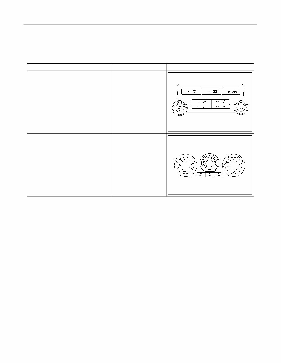
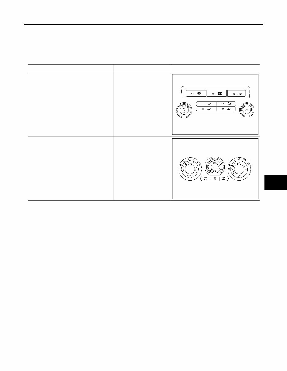
HAC-4 < BASIC INSPECTION > [MANUAL A/C (TYPE 1)] MANUAL A/C IDENTIFICATION TABLE BASIC INSPECTION MANUAL A/C IDENTIFICATION TABLE Application Table INFOID:0000000005268863 Manual A/C Type Description Visual Identification Manual A/C (Type 1) Two Control Dial System [with variable blower control (VBC)] Manual A/C (Type 2) Three Control Dial System [without variable blower con- trol (VBC)] AWIIA0481ZZ AWIIA1228ZZ Revision: July 2009 2010 Xterra
DIAGNOSIS AND REPAIR WORKFLOW HAC-5 < BASIC INSPECTION > [MANUAL A/C (TYPE 1)] C D E F G H J K L M A B HAC N O P DIAGNOSIS AND REPAIR WORKFLOW How to Perform Trouble Diagnosis For Quick And Accurate Repair INFOID:0000000005268864 WORK FLOW 1.LISTEN TO CUSTOMER COMPLAINT Listen to customer complaint. Get detailed information about the conditions and environment when the symp- tom occurs. >> GO TO 2 2.CHECK FOR SERVICE BULLETINS Check for any service bulletins. >> GO TO 3. 3.VERIFY THE SYMPTOM WITH OPERATIONAL CHECK Verify the symptom with operational check. Refer to HAC-6, "Operational Check" . Can a symptom be duplicated? YES >> Go to trouble diagnosis. Refer to HAC-57, "Symptom Matrix Chart" . NO >> GO TO 4. 4.PERFORM THE FRONT AIR CONTROL SELF-DIAGNOSIS Perform front air control self-diagnosis. Refer to HAC-17, "Front Air Control Self-Diagnosis" . >> If any diagnostic trouble codes set. Refer to HAC-17, "Front Air Control Self-Diagnosis Chart" . >> Confirm the repair by performing operational check. Refer to HAC-6, "Operational Check" . Revision: July 2009 2010 Xterra
HAC-6 < BASIC INSPECTION > [MANUAL A/C (TYPE 1)] INSPECTION AND ADJUSTMENT INSPECTION AND ADJUSTMENT Operational Check INFOID:0000000005268865 The purpose of the operational check is to confirm that the system operates properly. CHECKING BLOWER 1. Turn blower control dial clockwise. Blower should operate on low speed. 2. Turn the blower control dial again, and continue checking each blower speed until all speeds are checked. 3. Leave blower on HI speed. If NG, go to trouble diagnosis procedure for HAC-33, "Front Blower Motor Diagnosis Procedure" . If OK, continue with next check. CHECKING DISCHARGE AIR Press each mode switch and confirm that discharge air comes out according to the air distribution table. Refer tot HAC-12, "Discharge Air Flow" . Mode door position is checked in the next step. If NG, go to trouble diagnosis procedure for HAC-20, "Mode Door Motor Diagnosis Procedure" . If OK, continue with next check. NOTE: Confirm that the A/C compressor clutch is engaged (sound or visual inspection) and intake door position is at fresh when the DEF ( ) or D/F ( ) is selected. CHECKING RECIRCULATION 1. Press recirculation ( ) switch one time. Recirculation indicator should illuminate. 2. Press recirculation ( ) switch one more time. Recirculation indicator should go off. 3. Listen for intake door position change (blower sound should change slightly). If NG, go to trouble diagnosis procedure for HAC-30, "Intake Door Motor Diagnosis Procedure" . If OK, continue with next check. NOTE: Confirm that the compressor clutch is engaged (sound or visual inspection) and intake door position is at fresh when the DEF or D/F is selected. CHECKING TEMPERATURE DECREASE 1. Rotate temperature control dial counterclockwise. 2. Check for cold air at appropriate discharge air outlets. If NG, listen for sound of air mix door motor operation if OK, go to trouble diagnosis procedure for HAC-58, "Component Function Check" . If air mix door motor appears to be malfunctioning, go to HAC-25, "Air Mix Door Motor Component Function Check" . If OK, continue with next check. CHECKING TEMPERATURE INCREASE 1. Rotate temperature control dial clockwise. 2. Check for hot air at appropriate discharge air outlets. If NG, listen for sound of air mix door motor operation. If OK, go to trouble diagnosis procedure for HAC-66, "Component Function Check" . If air mix door motor (front) appears to be malfunctioning, go to HAC-25, "Air Mix Door Motor Component Function Check" . If OK, continue with next check. CHECK A/C SWITCH 1. Press A/C switch with the blower switch ON. 2. A/C switch indicator will turn ON. • Confirm that the compressor clutch engages (sound or visual inspection). If NG, go to trouble diagnosis procedure for HAC-38, "Magnet Clutch Diagnosis Procedure" . If OK, continue with next check. Conditions : Engine running and at normal operating temperature Revision: July 2009 2010 Xterra
MANUAL A/C IDENTIFICATION TABLE HAC-7 < FUNCTION DIAGNOSIS > [MANUAL A/C (TYPE 1)] C D E F G H J K L M A B HAC N O P FUNCTION DIAGNOSIS MANUAL A/C IDENTIFICATION TABLE Application Table INFOID:0000000005268866 Manual A/C Type Description Visual Identification Manual A/C (Type 1) Two Control Dial System [with variable blower control (VBC)] Manual A/C (Type 2) Three Control Dial System [without variable blower con- trol (VBC)] AWIIA0481ZZ AWIIA1228ZZ Revision: July 2009 2010 Xterra
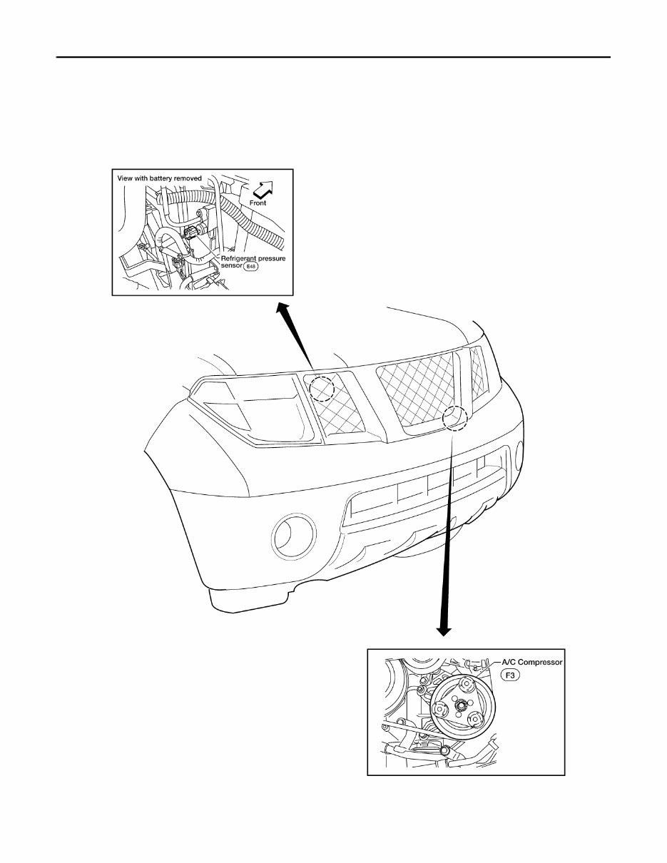
HAC-8 < FUNCTION DIAGNOSIS > [MANUAL A/C (TYPE 1)] FUNCTION INFORMATION FUNCTION INFORMATION Component Part Location INFOID:0000000005268867 ENGINE COMPARTMENT WJIA1489E Revision: July 2009 2010 Xterra
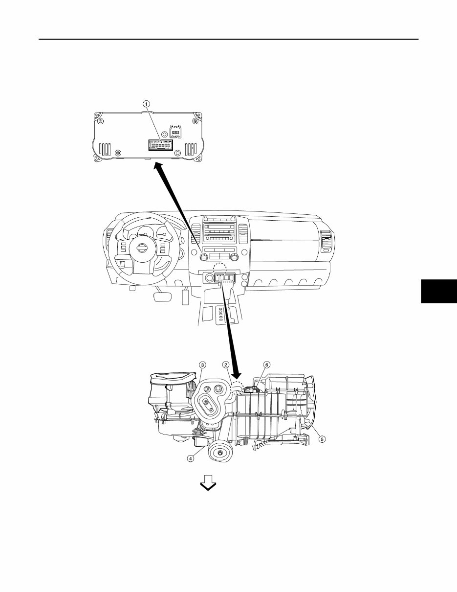
FUNCTION INFORMATION HAC-9 < FUNCTION DIAGNOSIS > [MANUAL A/C (TYPE 1)] C D E F G H J K L M A B HAC N O P PASSENGER COMPARTMENT ⇒ :Front 1. Front air control M50 2. Intake sensor M146 3. Intake door motor M58 4. Variable blower control M121 5. Mode door motor M142 6. Air mix door motor M148 AWIIA1198ZZ Revision: July 2009 2010 Xterra
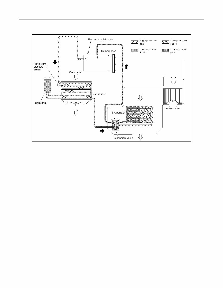
HAC-10 < FUNCTION DIAGNOSIS > [MANUAL A/C (TYPE 1)] REFRIGERATION SYSTEM REFRIGERATION SYSTEM Refrigerant Cycle INFOID:0000000005561468 REFRIGERANT FLOW The refrigerant flows in the standard pattern, that is, through the compressor, the condenser with liquid tank, through the front evaporator, and back to the compressor. The refrigerant evaporation through the evaporator coil is controlled by the front externally equalized expansion valve, located inside the front evaporator case. FREEZE PROTECTION The compressor cycles on and off to maintain the evaporator temperature within a specified range. When the evaporator coil temperature falls below a specified point, the intake sensor interrupts the compressor opera- tion. When the evaporator coil temperature rises above the specification, the intake sensor allows compressor operation. Refrigerant System Protection INFOID:0000000005561469 REFRIGERANT PRESSURE SENSOR The refrigerant system is protected against excessively high- or low-pressures by the refrigerant pressure sen- sor, located on the condenser. If the system pressure rises above or falls below the specifications, the refriger- ant pressure sensor detects the pressure inside the refrigerant line and sends a voltage signal to the ECM. The ECM de-energizes the A/C relay to disengage the magnetic compressor clutch when pressure on the high pressure side detected by refrigerant pressure sensor is over about 2,746 kPa (28 kg/cm 2 , 398 psi), or below about 120 kPa (1.22 kg/cm 2 , 17.4 psi). PRESSURE RELIEF VALVE The refrigerant system is also protected by a pressure relief valve, located in the rear head of the compressor. When the pressure of refrigerant in the system increases to an abnormal level [more than 2,990 kPa (30.5 kg/ cm 2 , 433.6 psi)], the release port on the pressure relief valve automatically opens and releases refrigerant into the atmosphere. WJIA1482E Revision: July 2009 2010 Xterra
The 2010 Nissan Xterra Service & Repair Manual is an essential tool for any DIY mechanic or owner of this rugged and reliable vehicle. With step-by-step instructions, clear images, and exploded-view illustrations, this manual contains everything you need to troubleshoot and repair your Xterra.
Regular maintenance is crucial for the longevity of your vehicle, and this manual provides the manufacturer's recommended procedures for keeping your Xterra in top condition. Even if properly maintained, parts will eventually wear out and need to be replaced, and this manual has you covered with troubleshooting charts and replacement procedures.
Gone are the days of flipping through hundreds of pages or dealing with greasy, torn, or lost pages. This digital manual can be easily carried around, searched, bookmarked, and even printed out for those who prefer a physical copy. It is compatible with various electronic devices, including PCs, Macs, smartphones, and tablets.
Don't let repair costs and unreliable vehicles hold you back. With the 2010 Nissan Xterra Service & Repair Manual, you can save money on repairs, increase your vehicle's reliability, and keep the repair shop at bay. Get yours today and take control of your Xterra's maintenance needs.