Description GUID-F4D5886C-EEFA-4F5E-AF03-029E3A5BCEFC This volume explains “Removal, Disassembly, Installation, Inspection and Adjustment” and “Trouble Diagnoses”.
Terms GUID-27071AFF-74FC-4D99-BFFE-289CD36D2F45 The captions WARNING and CAUTION warn you of steps that must be followed to prevent personal injury and/or damage to some part of the vehicle. WARNING indicates the possibility of personal injury if instructions are not followed. CAUTION indicates the possibility of component damage if instructions are not followed. BOLD TYPED STATEMENTS except WARNING and CAUTION give you helpful information. Standard value: Tolerance at inspection and adjustment. Limit value: The maximum or minimum limit value that should not be exceeded at inspection and adjustment.
Units GUID-3AF4F5BD-A814-4D43-9A8B-A265A92C6725 The UNITS given in this manual are primarily expressed as the SI UNIT (International System of Unit), and alternatively expressed in the metric system and in the yard/pound system. Also with regard to tightening torque of bolts and nuts, there are descriptions both about range and about the standard tightening torque. “Example” Range Outer Socket Lock Nut : 59 - 78 N·m (6.0 - 8.0 kg-m, 43 - 58 ft-lb) Standard Drive Shaft Installation Bolt : 44.3 N·m (4.5 kg-m, 33 ft-lb)
Contents GUID-51FF59D2-4529-40DA-ADF6-2ACA1440DFCD THE CONTENTS are listed on the first page of each section. THE TITLE is indicated on the upper portion of each page and shows the part or system. THE PAGE NUMBER of each section consists of two or three letters which designate the particular section and a number (e.g. “BR-5”). THE SMALL ILLUSTRATIONS show the important steps such as inspection, use of special tools, knacks of work and hidden or tricky steps which are not shown in the previous large illustrations. Assembly, inspection and adjustment procedures for the complicated units such as the automatic transaxle or transmission, etc. are presented in a step-by-step format where necessary.
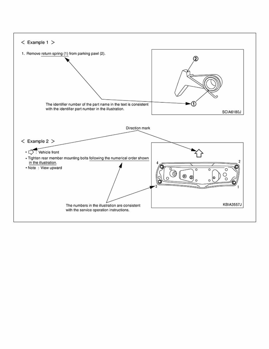
Relation between Illustrations and Descriptions GUID-9F72B7FA-953C-48DB-8235-285B7CE13376 The following sample explains the relationship between the part description in an illustration, the part name in the text and the service procedures. GUID-NISSAIA0519E
Description GUID-5B0756EF-8CCA-4009-939D-613712CCB1F3 Note: Trouble diagnoses indicate work procedures required to diagnose problems effectively. Observe the following instructions before diagnosing. Before performing trouble diagnoses, read the “Work Flow” in each section. After repairs, re-check that the problem has been completely eliminated. Refer to Component Parts and Harness Connector Location for the Systems described in each section for identification/location of components and harness connectors. When checking circuit continuity, ignition switch should be OFF. Refer to the Circuit Diagram for quick pinpoint check. If you need to check circuit continuity between harness connectors in more detail, such as when a sub-harness is used, refer to Wiring Diagram in each individual section and Harness Layout in PG section for identification of harness connectors. Before checking voltage at connectors, check battery voltage. After accomplishing the Diagnosis Procedures and Electrical Components Inspection, make sure that all harness connectors are reconnected as they were.
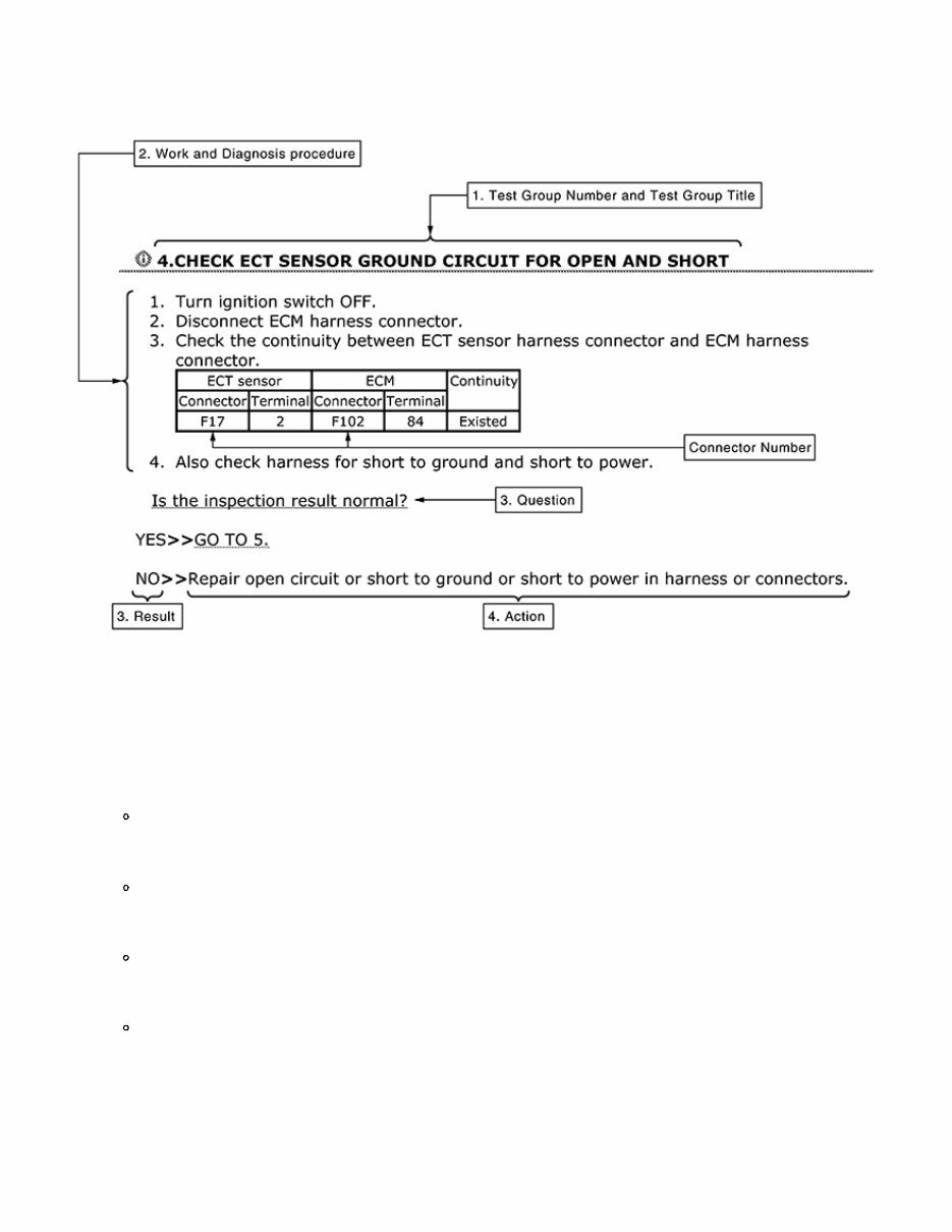
How to Follow Test Groups in Trouble Diagnosis GUID-4330B761-15C6-4BF9-8349-71BB4F4AB1DB GUID-NISJPAIA0021GB 1. Test group number and test group title Test group number and test group title are shown in the upper portion of each test group. 2. Work and diagnosis procedure Start to diagnose a problem using procedures indicated in enclosed test groups. 3. Questions and results Questions and required results are indicated in test group. 4. Action Next action for each test group is indicated based on result of each question.
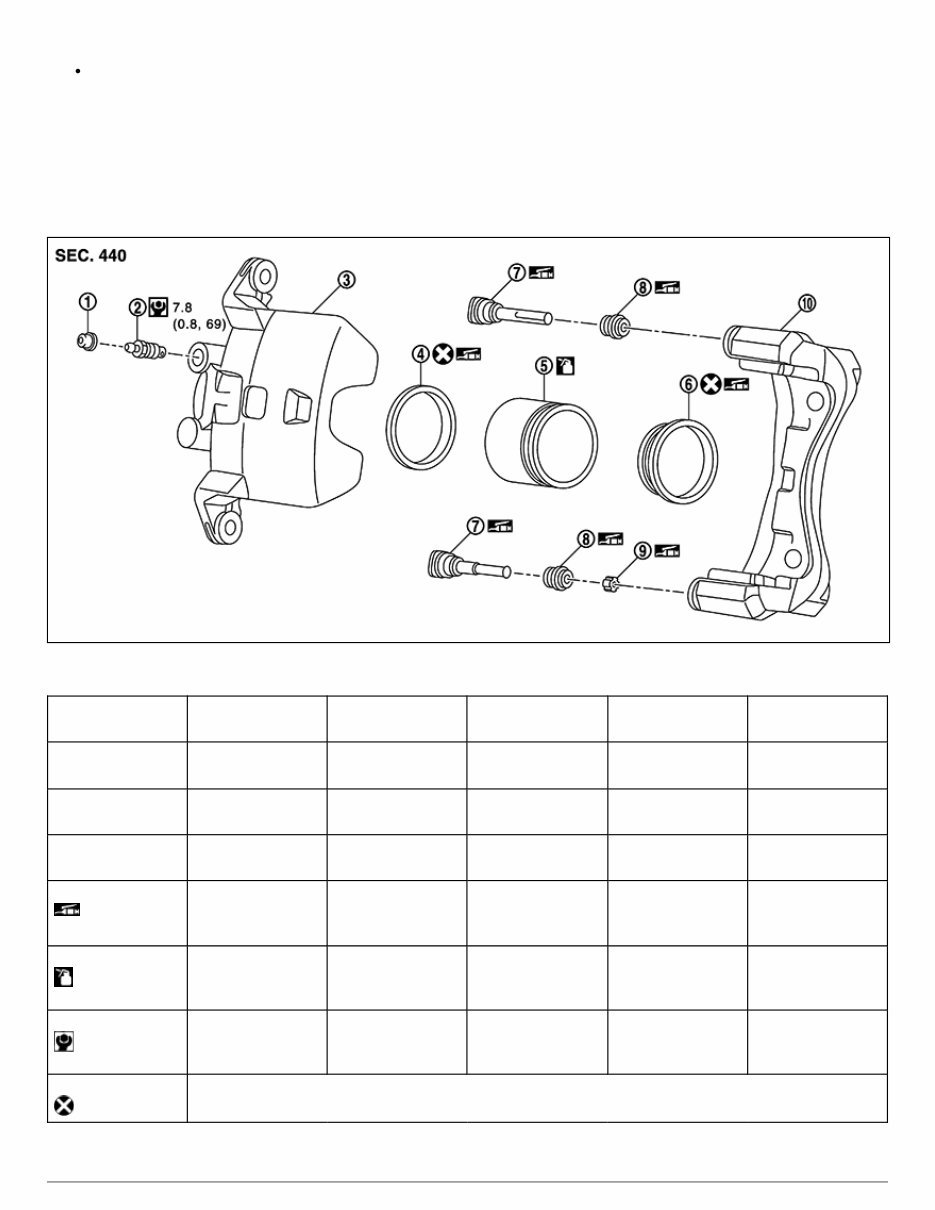
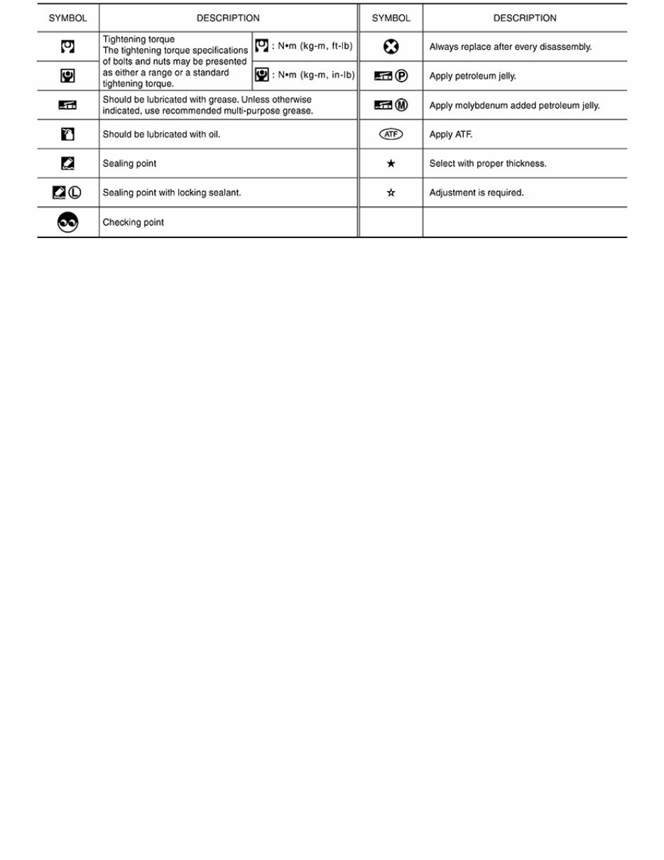
Components GUID-B701D656-1637-440A-84AF-DA4CEFE9E988 THE LARGE ILLUSTRATIONS are exploded views (see the following) and contain tightening torques, lubrication points, section number of the PARTS CATALOG (e.g. SEC. 440) and other information necessary to perform repairs. The illustrations should be used in reference to service matters only. When ordering parts, refer to the appropriate PARTS CATALOG. Components shown in an illustration may be identified by a circled number. When this style of illustration is used, the text description of the components will follow the illustration. GUID-NISJPFIA0511GB 1. Cap 2. Bleeder valve 3. Cylinder body 4. Piston seal 5. Piston 6. Piston boot 7. Sliding pin 8. Sliding pin boot 9. Bushing 10. Torque member : Apply rubber grease. : Apply brake fluid. : N·m (kg-m, in-lb) : Always replace after every disassembly SYMBOLS
GUID-NISSAIA0749E
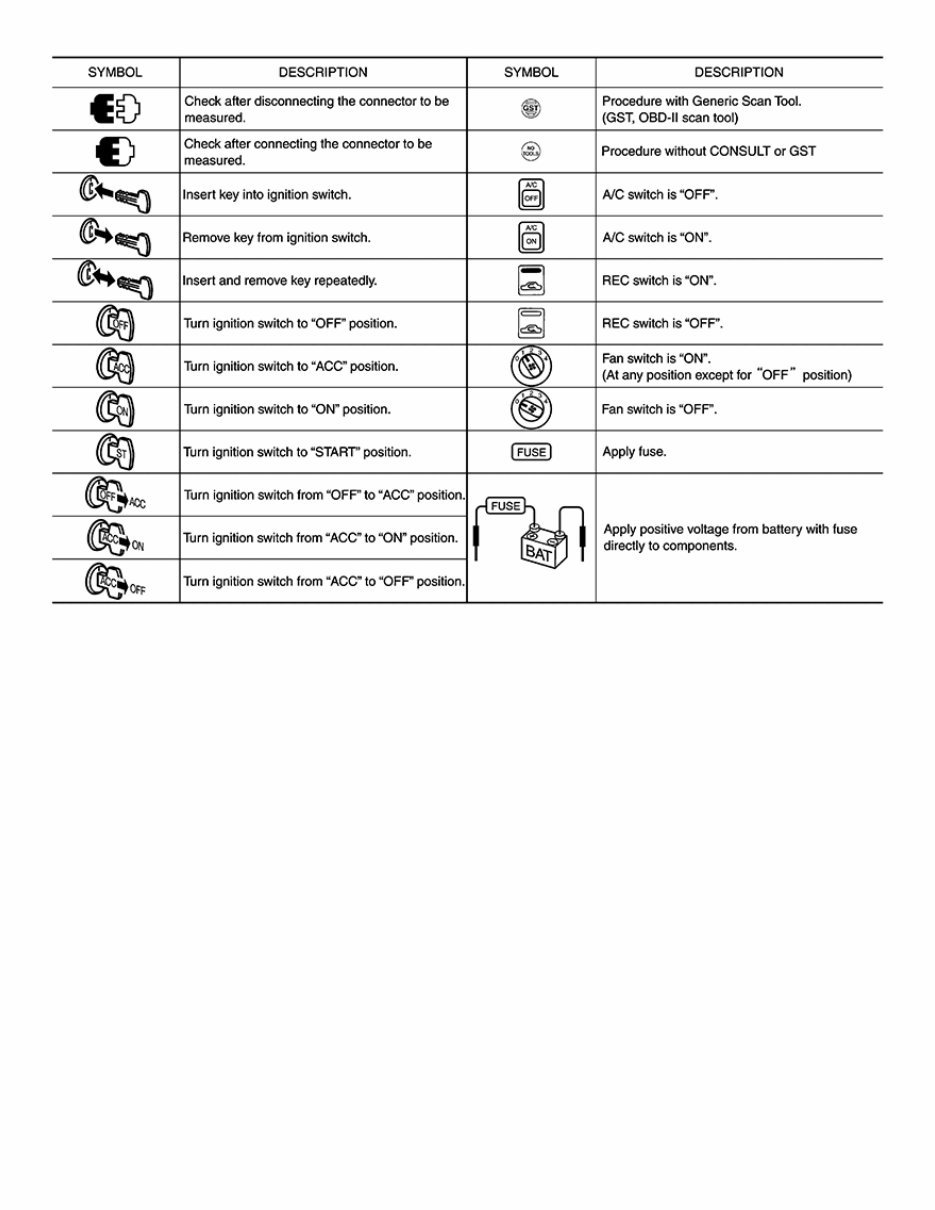
Key to Symbols Signifying Measurements or Procedures GUID-8645F2AE-B372-4F8B-B9D2-CBBA6A4EE444 GUID-NISJPAIA0982GB
Revolutionize your vehicle maintenance routine with the 2019 Nissan Versa Sedan Service & Repair Manual. This comprehensive repair manual contains all the troubleshooting and replacement procedures recommended by the manufacturer, making it the ultimate resource for DIY fixes.
While your Nissan Versa Sedan is built to last, regular maintenance is vital to keep it running smoothly. With this service & repair manual, you'll have access to everything you need to know to keep your vehicle in top shape. No more flipping through hundreds of pages or dealing with greasy, torn, or lost pages. This manual is conveniently organized with step-by-step instructions, exploded-view illustrations, and clear images, making it easy to find the information you need.
Compatible with a wide range of electronic devices, including smartphones, tablets, and computers, this manual is easily accessible whenever and wherever you need it. Plus, with the option to print it out, you can have a physical copy on hand as well.
Keep your vehicle reliable and save on repair costs with the 2019 Nissan Versa Sedan Service & Repair Manual. Get yours today and take control of your vehicle's maintenance.
Compatible Models:
2019 Nissan Versa Sedan S
2019 Nissan Versa Sedan S Plus
2019 Nissan Versa Sedan SV
2019 Nissan Versa Sedan SV Special Edition
2019 Nissan Versa Sedan SR
Features:
Manufacturer-recommended troubleshooting and replacement procedures
Step-by-step instructions
Exploded-view illustrations
Clear images
Conveniently organized for easy navigation
Compatible with electronic devices and can be printed out







 Lifetime Access




