Description TM NISC0000000014221327 This volume explains “Removal, Disassembly, Installation, Inspection and Adjustment” and “Trouble Diagnoses”.
Terms The captions WARNING and CAUTION warn you of steps that must be followed to prevent personal injury and/or damage to some part of the vehicle. WARNING indicates the possibility of personal injury if instructions are not followed. CAUTION indicates the possibility of component damage if instructions are not followed. BOLD TYPED STATEMENTS except WARNING and CAUTION give you helpful information. Standard value: Tolerance at inspection and adjustment. Limit value: The maximum or minimum limit value that should not be exceeded at inspection and adjustment.
Units The UNITS given in this manual are primarily expressed as the SI UNIT (International System of Unit), and alternatively expressed in the metric system and in the yard/pound system. Also with regard to tightening torque of bolts and nuts, there are descriptions both about range and about the standard tightening torque. “Example” Range Outer Socket Lock Nut : 59 - 78 N·m (6.0 - 8.0 kg-m, 43 - 58 ft-lb) Standard Drive Shaft Installation Bolt : 44.3 N·m (4.5 kg-m, 33 ft-lb)
Contents NISC0000000014221330 A QUICK REFERENCE INDEX, a black tab (e.g. ) is provided on the first page. You can quickly find the first page of each section by matching it to the section's black tab. THE CONTENTS are listed on the first page of each section. THE TITLE is indicated on the upper portion of each page and shows the part or system. THE PAGE NUMBER of each section consists of two or three letters which designate the particular section and a number (e.g. “BR-5”). THE SMALL ILLUSTRATIONS show the important steps such as inspection, use of special tools, knacks of work and hidden or tricky steps which are not shown in the previous large illustrations. Assembly, inspection and adjustment procedures for the complicated units such as the automatic transaxle or transmission, etc. are presented in a step-by-step format where necessary.
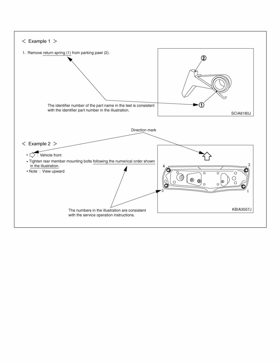
Relation between Illustrations and Descriptions NISC0000000014221331 The following sample explains the relationship between the part description in an illustration, the part name in the text and the service procedures. NISC0000000014221331-01-AIA0519E
Description NOTE: Trouble diagnoses indicate work procedures required to diagnose problems effectively. Observe the following instructions before diagnosing. Before performing trouble diagnoses, read the “Work Flow” in each section. After repairs, re-check that the problem has been completely eliminated. Refer to Component Parts and Harness Connector Location for the Systems described in each section for identification/location of components and harness connectors. When checking circuit continuity, ignition switch should be OFF. Refer to the Circuit Diagram for quick pinpoint check. If you need to check circuit continuity between harness connectors in more detail, such as when a sub-harness is used, refer to Wiring Diagram in each individual section and Harness Layout in PG section for identification of harness connectors. Before checking voltage at connectors, check battery voltage. After accomplishing the Diagnosis Procedures and Electrical Components Inspection, make sure that all harness connectors are reconnected as they were.
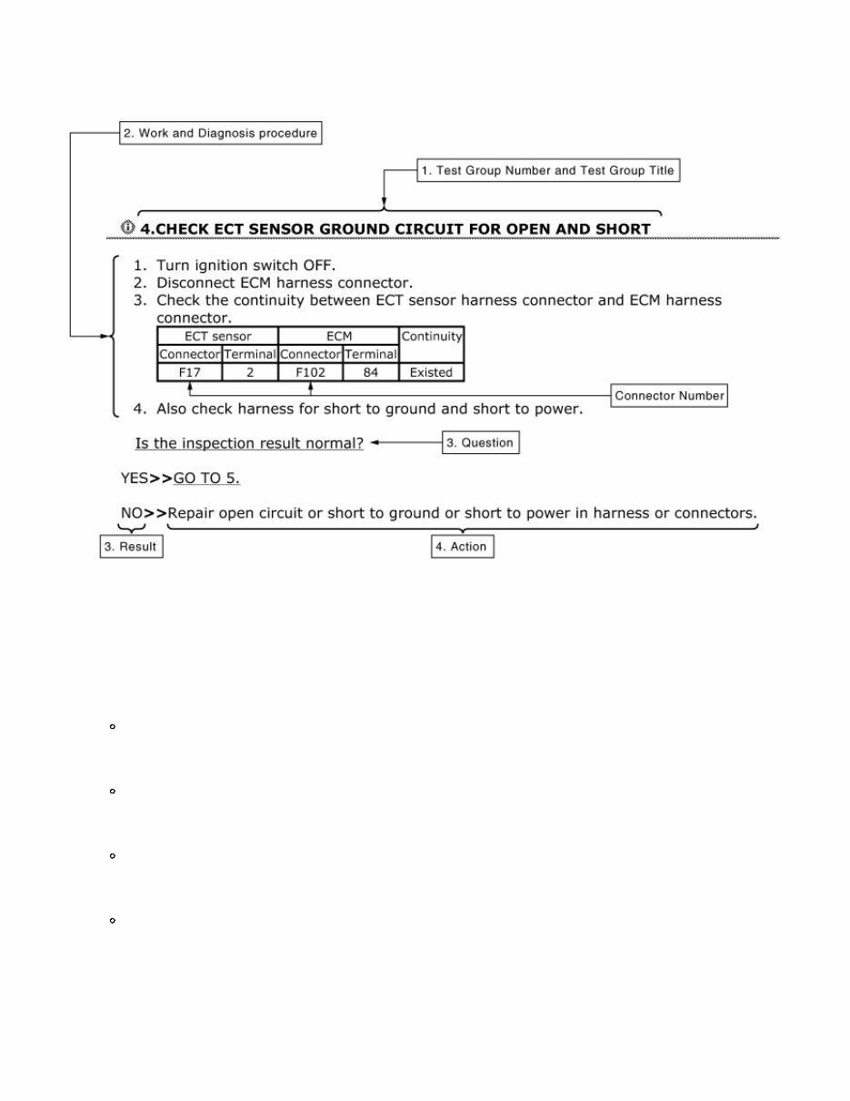
How to Follow Test Groups in Trouble Diagnosis NISC0000000014221334-01-JPAIA0021GB 1. Test group number and test group title Test group number and test group title are shown in the upper portion of each test group. 2. Work and diagnosis procedure Start to diagnose a problem using procedures indicated in enclosed test groups. 3. Questions and results Questions and required results are indicated in test group. 4. Action Next action for each test group is indicated based on result of each question.
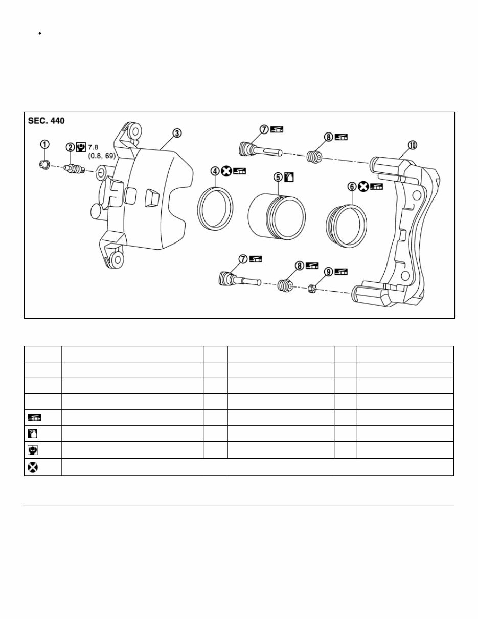
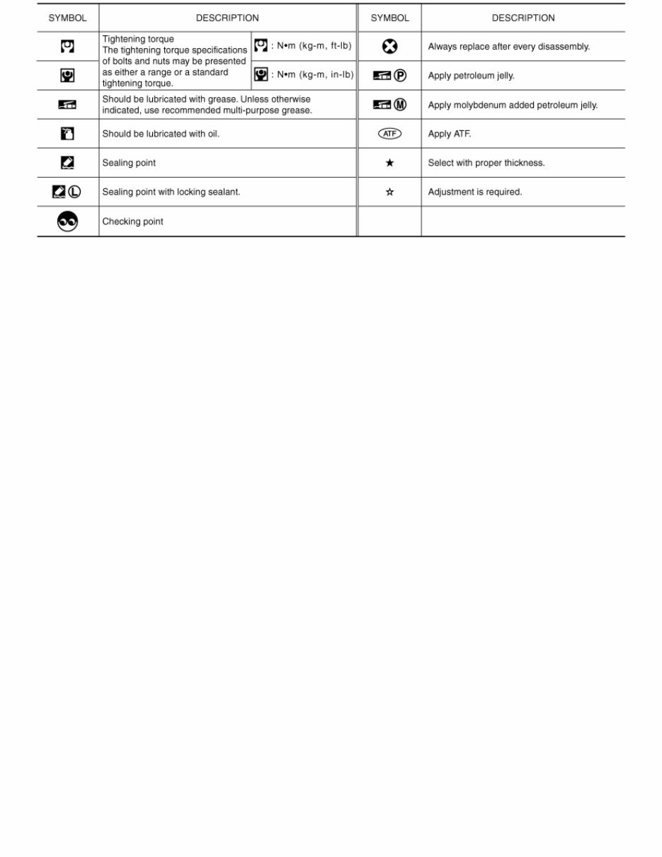
Components THE LARGE ILLUSTRATIONS are exploded views (see the following) and contain tightening torques, lubrication points, section number of the PARTS CATALOG (e.g. SEC. 440) and other information necessary to perform repairs. The illustrations should be used in reference to service matters only. When ordering parts, refer to the appropriate PARTS CATALOG. Components shown in an illustration may be identified by a circled number. When this style of illustration is used, the text description of the components will follow the illustration. NISC0000000014221332-01-JPFIA0511GB 1. Cap 2. Bleeder valve 3. Cylinder body 4. Piston seal 5. Piston 6. Piston boot 7. Sliding pin 8. Sliding pin boot 9. Bushing 10. Torque member : Apply rubber grease. : Apply brake fluid. : N·m (kg-m, in-lb) : Always replace after every disassembly SYMBOLS
NISC0000000014221332-02-SAIA0749E
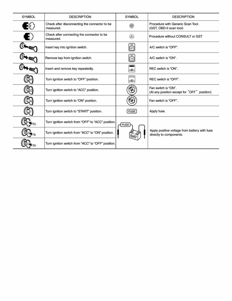
Key to Symbols Signifying Measurements or Procedures NISC0000000014221335-01-JPAIA0982GB
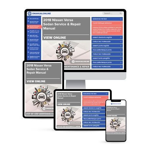
The 2018 Nissan Versa Sedan Service & Repair Manual is the ultimate resource for owners looking to maintain and repair their vehicle. This comprehensive manual provides everything you need to know about troubleshooting and replacing parts, complete with step-by-step instructions, clear images, and exploded-view illustrations.
No matter how durable your Nissan Versa Sedan is, regular maintenance is essential to keeping it in top condition. And when it comes time for repairs, a dependable service & repair manual is a must-have. With the manufacturer's recommended troubleshooting charts and replacement procedures at your fingertips, you can save on costly repairs and increase your vehicle's reliability.
But the benefits don't stop there. This manual is easily accessible on any electronic device, including PC and Mac computers, smartphones, and tablets. And with the ability to search, bookmark, and even print out specific pages, it's a convenient and user-friendly alternative to traditional bound manuals.
So why wait? Get your hands on the 2018 Nissan Versa Sedan Service & Repair Manual and take control of your vehicle's maintenance today. You'll be able to keep the repair shop at bay and enjoy the peace of mind that comes with knowing your Nissan Versa Sedan is in good hands.



 Lifetime Access




