CO-1 ENGINE C D E F G H I J K L M SECTION CO A CO N O P CONTENTS ENGINE COOLING SYSTEM HR16DE PRECAUTION .............................................. 2 PRECAUTIONS .................................................. 2 Precaution for Supplemental Restraint System (SRS) "AIR BAG" and "SEAT BELT PRE-TEN- SIONER" .................................................................. 2 PREPARATION ........................................... 3 PREPARATION .................................................. 3 Special Service Tool ................................................ 3 Commercial Service Tool ......................................... 3 SYSTEM DESCRIPTION ............................. 4 DESCRIPTION ................................................... 4 Engine Cooling System ............................................ 4 Engine Cooling System Schematic .......................... 5 SYMPTOM DIAGNOSIS .............................. 6 OVERHEATING CAUSE ANALYSIS ................. 6 Troubleshooting Chart .............................................. 6 PERIODIC MAINTENANCE ......................... 8 ENGINE COOLANT ........................................... 8 Inspection ................................................................. 8 Draining Engine Coolant .......................................... 8 Refilling Engine Coolant ........................................... 9 Flushing Cooling System ....................................... 10 RADIATOR ........................................................12 RADIATOR CAP .......................................................12 RADIATOR CAP : Inspection .................................12 RADIATOR ................................................................12 RADIATOR : Inspection ..........................................12 REMOVAL AND INSTALLATION .............. 14 RADIATOR ........................................................ 14 Exploded View ........................................................14 Removal and Installation ........................................14 COOLING FAN .................................................. 17 Exploded View ........................................................17 Removal and Installation ........................................17 Disassembly and Assembly ....................................18 WATER PUMP .................................................. 19 Exploded View ........................................................19 Removal and Installation ........................................19 THERMOSTAT .................................................. 21 Exploded View ........................................................21 Removal and Installation ........................................21 WATER OUTLET .............................................. 24 Exploded View ........................................................24 Removal and Installation ........................................25 SERVICE DATA AND SPECIFICATIONS (SDS) ........................................................... 26 SERVICE DATA AND SPECIFICATIONS (SDS) ................................................................. 26 Standard and Limit .................................................26 Revision: July 2011 2012 Versa Sedan
CO-2 < PRECAUTION > [HR16DE] PRECAUTIONS PRECAUTION PRECAUTIONS Precaution for Supplemental Restraint System (SRS) "AIR BAG" and "SEAT BELT PRE-TENSIONER" INFOID:0000000007774133 The Supplemental Restraint System such as “AIR BAG” and “SEAT BELT PRE-TENSIONER”, used along with a front seat belt, helps to reduce the risk or severity of injury to the driver and front passenger for certain types of collision. This system includes seat belt switch inputs and dual stage front air bag modules. The SRS system uses the seat belt switches to determine the front air bag deployment, and may only deploy one front air bag, depending on the severity of a collision and whether the front occupants are belted or unbelted. Information necessary to service the system safely is included in the SR and SB section of this Service Man- ual. WARNING: • To avoid rendering the SRS inoperative, which could increase the risk of personal injury or death in the event of a collision which would result in air bag inflation, all maintenance must be performed by an authorized NISSAN/INFINITI dealer. • Improper maintenance, including incorrect removal and installation of the SRS, can lead to personal injury caused by unintentional activation of the system. For removal of Spiral Cable and Air Bag Module, see the SR section. • Do not use electrical test equipment on any circuit related to the SRS unless instructed to in this Service Manual. SRS wiring harnesses can be identified by yellow and/or orange harnesses or har- ness connectors. PRECAUTIONS WHEN USING POWER TOOLS (AIR OR ELECTRIC) AND HAMMERS WARNING: • When working near the Airbag Diagnosis Sensor Unit or other Airbag System sensors with the Igni- tion ON or engine running, DO NOT use air or electric power tools or strike near the sensor(s) with a hammer. Heavy vibration could activate the sensor(s) and deploy the air bag(s), possibly causing serious injury. • When using air or electric power tools or hammers, always switch the Ignition OFF, disconnect the battery, and wait at least 3 minutes before performing any service. Revision: July 2011 2012 Versa Sedan
PREPARATION CO-3 < PREPARATION > [HR16DE] C D E F G H I J K L M A CO N P O PREPARATION PREPARATION Special Service Tool INFOID:0000000007687119 The actual shapes of Kent-Moore tools may from those of special service tools illustrated here. Commercial Service Tool INFOID:0000000007687120 Tool number (Kent-Moore No.) Tool name Description KV991J0070 (J-45695) Coolant Refill Tool Refilling engine cooling system EG17650301 (J-33984-A) Radiator cap tester adapter Adapting radiator cap tester to radiator cap and radiator filler neck a: 28 (1.10) dia. b: 31.4 (1.236) dia. c: 41.3 (1.626) dia. Unit: mm (in) — (J-23688) Engine coolant refractometer Checking concentration of ethylene glycol in engine coolant LMA053 S-NT564 WBIA0539E Tool name Description Power tool Loosening bolts and nuts Radiator cap tester Checking radiator and radiator cap PBIC0190E PBIC1982E Revision: July 2011 2012 Versa Sedan
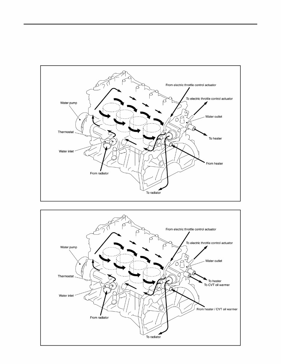
CO-4 < SYSTEM DESCRIPTION > [HR16DE] DESCRIPTION SYSTEM DESCRIPTION DESCRIPTION Engine Cooling System INFOID:0000000007616594 M/T models CVT models JSBIA1096GB JSBIA1297GB Revision: July 2011 2012 Versa Sedan
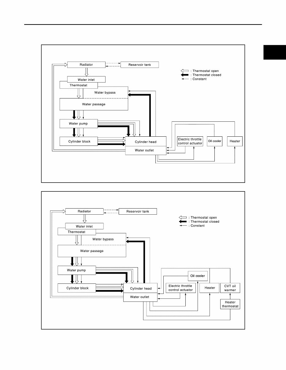
DESCRIPTION CO-5 < SYSTEM DESCRIPTION > [HR16DE] C D E F G H I J K L M A CO N P O Engine Cooling System Schematic INFOID:0000000007616595 M/T models CVT models AWBIA1141GB AWBIA1142GB Revision: July 2011 2012 Versa Sedan
CO-6 < SYMPTOM DIAGNOSIS > [HR16DE] OVERHEATING CAUSE ANALYSIS SYMPTOM DIAGNOSIS OVERHEATING CAUSE ANALYSIS Troubleshooting Chart INFOID:0000000007576021 Symptom Check items Cooling sys- tem parts malfunction Poor heat transfer Water pump malfunction Worn or loose drive belt — Thermostat stuck closed Thermostat Damaged fins Dust contamination or pa- per clogging Physical damage Clogged radiator cooling tube Excess foreign material (rust, dirt, sand, etc.) Reduced air flow Cooling fan does not oper- ate Fan assembly — High resistance to fan rota- tion Damaged fan blades Damaged radiator shroud — Radiator shroud — Improper engine coolant mixture ratio — Engine coolant viscosity — Poor engine coolant quality — Periodic maintenance — Insufficient engine coolant Engine coolant leakage Cooling hose Loose clamp Cracked hose Water pump Poor sealing Radiator cap Loose Poor sealing Radiator O-ring for damage, deterio- ration or improper fitting Cracked radiator tank Cracked radiator core Reservoir tank Cracked reservoir tank Overflowing reservoir tank Exhaust gas leaking into cooling system Cylinder head deterioration Cylinder head gasket deteri- oration Revision: July 2011 2012 Versa Sedan
OVERHEATING CAUSE ANALYSIS CO-7 < SYMPTOM DIAGNOSIS > [HR16DE] C D E F G H I J K L M A CO N P O Except cool- ing system parts mal- function — Overload on engine Abusive driving High engine rpm under no load Driving in low gear for ex- tended time Driving at extremely high speed Power train system mal- function — Installed improper size wheels and tires Dragging brakes Improper ignition timing Blocked or restricted air flow Blocked bumper Installed front bumper fas- cia cover — Blocked radiator grille Mud contamination or paper clogging Blocked radiator Blocked air flow Blocked condenser Installed large fog lamp Symptom Check items Revision: July 2011 2012 Versa Sedan
CO-8 < PERIODIC MAINTENANCE > [HR16DE] ENGINE COOLANT PERIODIC MAINTENANCE ENGINE COOLANT Inspection INFOID:0000000007576022 CHECKING COOLING SYSTEM HOSES Check hoses for the following: • Improper attachment • Leaks • Cracks • Damage • Loose connections • Chafing • Deterioration CHECKING RESERVOIR LEVEL • Check that the reservoir tank engine coolant level is within the MAX (A) to MIN (B) range when the engine is cool. • Adjust the engine coolant level if necessary. CAUTION: Refill the engine cooling system with the specified coolant or equivalent. Refer to MA-12, " Fluids and Lubricants " . CHECKING COOLING SYSTEM FOR LEAKS To check for leaks, apply pressure to the cooling system using suit- able tool (A) and Tool (B). WARNING: Never remove the radiator cap when the engine is hot. Serious burns could occur from high-pressure coolant escaping from the radiator. CAUTION: Higher test pressure than specified may cause radiator damage. Draining Engine Coolant INFOID:0000000007576023 WARNING: • Never remove radiator cap when engine is hot. Serious burns could occur from high-pressure engine coolant escaping from radiator. • Wrap a thick cloth around the radiator cap. Slowly turn it a quarter of a turn to release built-up pres- sure. Then turn it all the way. 1. Remove engine undercover. Refer to EXT-15, " Exploded View " . JPBIA0102ZZ Tool number (B) : EG17650301 (J-33984-A) Testing pressure : Refer to CO-12, " RADIATOR : Inspection " . PBIC5121J Revision: July 2011 2012 Versa Sedan
ENGINE COOLANT CO-9 < PERIODIC MAINTENANCE > [HR16DE] C D E F G H I J K L M A CO N P O 2. Connect a drain hose to the radiator drain plug. • Use a suitable hose with the dimensions as shown. 3. Open radiator drain plug (A) at the bottom of radiator, and then remove radiator cap. : Vehicle front CAUTION: • Perform this step when engine is cold. • Do not spill engine coolant on the drive belt. 4. It is necessary to drain the cylinder block when draining all of engine coolant in the system. To drain the cylinder block, open the water drain plugs on cylinder block. Refer to EM-94, " Exploded View " . 5. Remove reservoir tank if necessary, and drain engine coolant and clean reservoir tank before installing. Refer to CO-14, " Exploded View " . 6. Check drained engine coolant for contaminants such as rust, corrosion or discoloration. If contaminated, flush the engine cooling system. Refer to CO-10, " Flushing Cooling System " . Refilling Engine Coolant INFOID:0000000007576024 1. Install the radiator drain plug. Install the reservoir tank and cylinder block drain plug, if removed. CAUTION: • Be sure to clean drain plug and install with a new O-ring. • Apply sealant to the threads of the cylinder block drain plug. Use Genuine High Performance Thread Sealant or equivalent. Refer to GI-15, " Recommended Chemical Products and Sealants " . 2. Set the vehicle heater controls to the full HOT and heater ON position. Turn the vehicle ignition ON with the engine OFF as necessary to activate the heater mode. Diameter (A) : 0.8 mm (0.31 in) Length (B) : 300 mm (11.81 in) JPBIA4770ZZ JSBIA1090ZZ Radiator drain plug : Refer to CO-14, " Exploded View " . Cylinder block drain plug : Refer to EM-94, " Exploded View " . Revision: July 2011 2012 Versa Sedan
CO-10 < PERIODIC MAINTENANCE > [HR16DE] ENGINE COOLANT 3. Install the Tool by installing the radiator cap adapter onto the radiator neck opening. Then attach the gauge body assembly with the refill tube and the venturi assembly to the radiator cap adapter. 4. Insert the refill hose into the coolant mixture container that is placed at floor level. Make sure the ball valve is in the closed position. Use recommended coolant or equivalent. Refer to MA-12, " Flu- ids and Lubricants " . 5. Install an air hose to the venturi assembly. The air pressure must be within specification. CAUTION: The compressed air supply must be equipped with an air dryer. 6. The vacuum gauge will begin to rise and there will be an audible hissing noise. During this process open the ball valve on the refill hose slightly. Coolant will be visible rising in the refill hose. Once the refill hose is full of coolant, close the ball valve. This will purge any air trapped in the refill hose. 7. Continue to draw the vacuum until the gauge reaches 28 inches of vacuum. The gauge may not reach 28 inches in high altitude locations; use the vacuum specifications based on the altitude above sea level. 8. When the vacuum gauge has reached the specified amount, disconnect the air hose and wait 20 seconds to see if the system loses any vacuum. If the vacuum level drops, perform any necessary repairs to the system and repeat steps 6 - 8 to bring the vacuum to the specified amount. Recheck for any leaks. 9. Place the coolant container (with the refill hose inserted) at the same level as the top of the radiator. Then open the ball valve on the refill hose so the coolant will be drawn up to fill the cooling system. The cooling system is full when the vacuum gauge reads zero. CAUTION: Do not allow the coolant container to get too low when filling, to avoid air from being drawn into the cooling system. 10. Remove the Tool from the radiator neck opening. 11. Fill the cooling system reservoir tank to the specified level and install the radiator cap. Run the engine to warm up the cooling system and top up the system as necessary. 12. Install engine undercover. Refer to EXT-15, " Exploded View " . Flushing Cooling System INFOID:0000000007576025 1. Install radiator drain plug and reservoir tank, if removed. Tool number : KV991J0070 (J-45695) Engine coolant capacity (with reservoir tank) : Refer to MA-12, " Fluids and Lubricants " . Compressed air supply pressure : 549 - 824 kPa (5.6 - 8.4 kg/cm 2 , 80 - 119 psi) LLIA0058E Altitude above sea level Vacuum gauge reading 0 - 100 m (328 ft) : 28 inches of vacuum 300 m (984 ft) : 27 inches of vacuum 500 m (1,641 ft) : 26 inches of vacuum 1,000 m (3,281 ft) : 24 - 25 inches of vacuum LLIA0057E Revision: July 2011 2012 Versa Sedan
Keep your 2014 Nissan Versa Note in top shape with the help of this comprehensive service & repair manual. Whether you prefer a Do-It-Yourself approach or want to have a better understanding of your vehicle, this manual has got you covered.
Containing every troubleshooting and replacement procedure recommended by the manufacturer, this manual includes step-by-step instructions, clear images, and exploded-view illustrations. No need to flip through hundreds of pages or worry about greasy, torn, or lost pages - simply carry this manual with you, search for specific information, and even bookmark your favorite pages.
Regular maintenance is essential for the durability of your vehicle, and this manual makes it easy to keep up with those maintenance tasks. It's compatible with various electronic devices, including PC and Mac computers, Android and Apple smartphones and tablets, and requires Adobe Reader (free) to access.
With this manual, you'll be able to save on repairs, increase your vehicle's reliability, and keep the repair shop at bay. So why wait? Get your hands on this essential guide and have all the information you need at your fingertips.