ACC-1 ENGINE C D E F G H I J K L M SECTION ACC A ACC N O P CONTENTS ACCELERATOR CONTROL SYSTEM PRECAUTION .............................................. 2 PRECAUTIONS .................................................. 2 Precaution for Supplemental Restraint System (SRS) "AIR BAG" and "SEAT BELT PRE-TEN- SIONER" .................................................................. 2 ON-VEHICLE REPAIR ................................. 3 ACCELERATOR CONTROL SYSTEM .............. 3 Removal and Installation ......................................... 3 SERVICE DATA AND SPECIFICATIONS (SDS) ............................................................ 6 SERVICE DATA AND SPECIFICATIONS (SDS) .................................................................. 6 Accelerator Control .................................................. 6 Revision: August 2009 2010 Titan
ACC-2 < PRECAUTION > PRECAUTIONS PRECAUTION PRECAUTIONS Precaution for Supplemental Restraint System (SRS) "AIR BAG" and "SEAT BELT PRE-TENSIONER" INFOID:0000000005385715 The Supplemental Restraint System such as “AIR BAG” and “SEAT BELT PRE-TENSIONER”, used along with a front seat belt, helps to reduce the risk or severity of injury to the driver and front passenger for certain types of collision. This system includes seat belt switch inputs and dual stage front air bag modules. The SRS system uses the seat belt switches to determine the front air bag deployment, and may only deploy one front air bag, depending on the severity of a collision and whether the front occupants are belted or unbelted. Information necessary to service the system safely is included in the SR and SB section of this Service Man- ual. WARNING: • To avoid rendering the SRS inoperative, which could increase the risk of personal injury or death in the event of a collision which would result in air bag inflation, all maintenance must be performed by an authorized NISSAN/INFINITI dealer. • Improper maintenance, including incorrect removal and installation of the SRS, can lead to personal injury caused by unintentional activation of the system. For removal of Spiral Cable and Air Bag Module, see the SR section. • Do not use electrical test equipment on any circuit related to the SRS unless instructed to in this Service Manual. SRS wiring harnesses can be identified by yellow and/or orange harnesses or har- ness connectors. PRECAUTIONS WHEN USING POWER TOOLS (AIR OR ELECTRIC) AND HAMMERS WARNING: • When working near the Airbag Diagnosis Sensor Unit or other Airbag System sensors with the Igni- tion ON or engine running, DO NOT use air or electric power tools or strike near the sensor(s) with a hammer. Heavy vibration could activate the sensor(s) and deploy the air bag(s), possibly causing serious injury. • When using air or electric power tools or hammers, always switch the Ignition OFF, disconnect the battery, and wait at least 3 minutes before performing any service. Revision: August 2009 2010 Titan
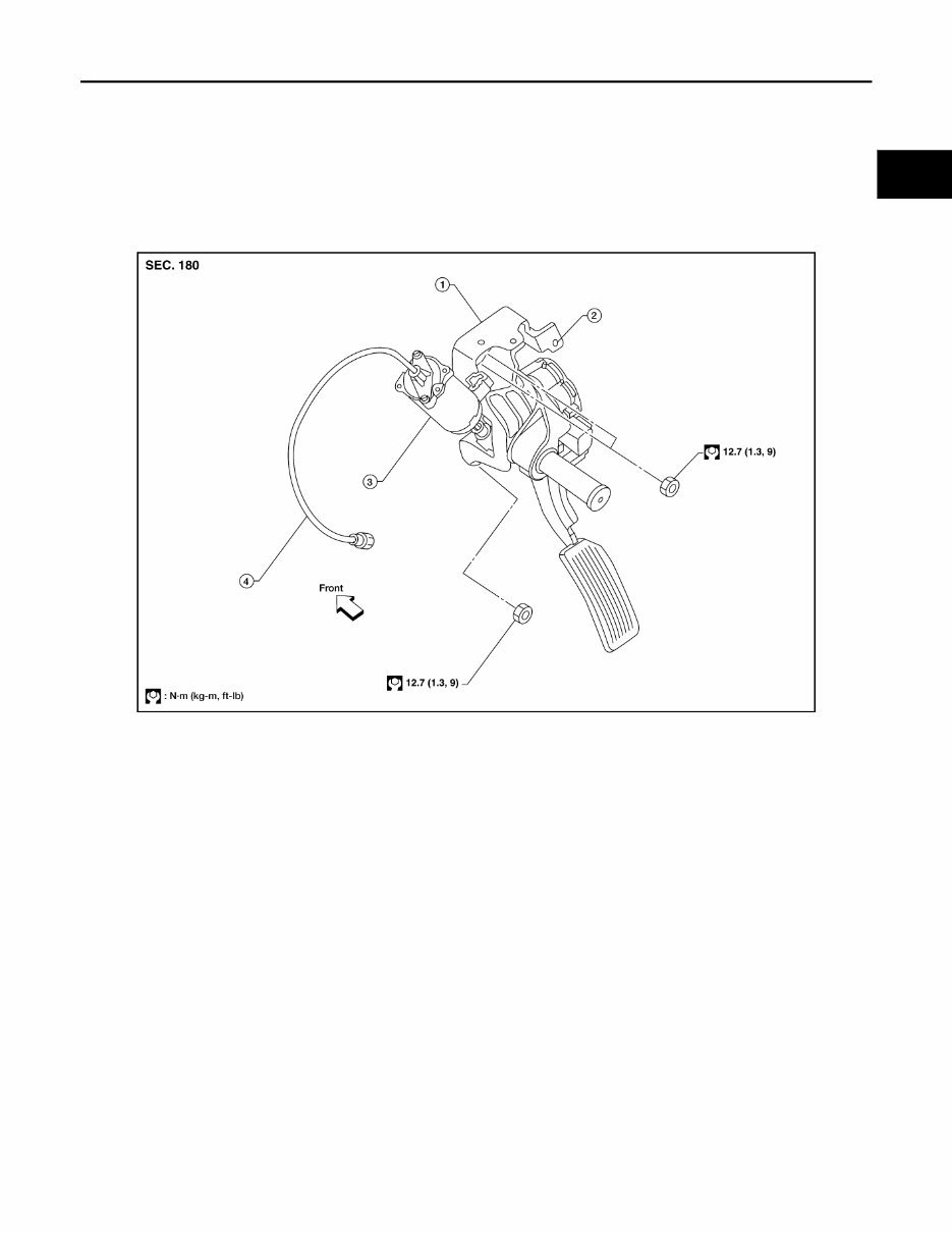
ACCELERATOR CONTROL SYSTEM ACC-3 < ON-VEHICLE REPAIR > C D E F G H I J K L M A ACC N P O ON-VEHICLE REPAIR ACCELERATOR CONTROL SYSTEM Removal and Installation INFOID:0000000005385716 ADJUSTABLE ACCELERATOR PEDAL ASSEMBLY Adjustable Accelerator Pedal CAUTION: • Do not disassemble the accelerator pedal adjusting mechanism. • Before removal and installation, the accelerator and brake pedals must be in the frontmost position. This is to align the base position of the accelerator and brake pedals. • Do not disassemble the accelerator pedal assembly. • Do not remove the accelerator pedal position sensor from the accelerator pedal bracket. • Avoid damage from dropping the accelerator pedal assembly during handling. • Keep the accelerator pedal assembly away from water. Removal 1. Move the accelerator and brake pedals to the frontmost position. 2. Turn the ignition switch OFF and disconnect the negative battery terminal. 3. Disconnect the adjustable brake pedal cable from the adjustable brake pedal. • Unlock, then pull the adjustable brake pedal cable to disconnect it from the adjustable brake pedal. LBIA0379E 1. Adjustable accelerator pedal assem- bly 2. Adjustable accelerator pedal bracket (part of the accelerator pedal assembly) 3. Adjustable pedal electric motor (part of the accelerator pedal assembly) 4. Adjustable brake pedal cable (part of the accelerator pedal assembly) Revision: August 2009 2010 Titan
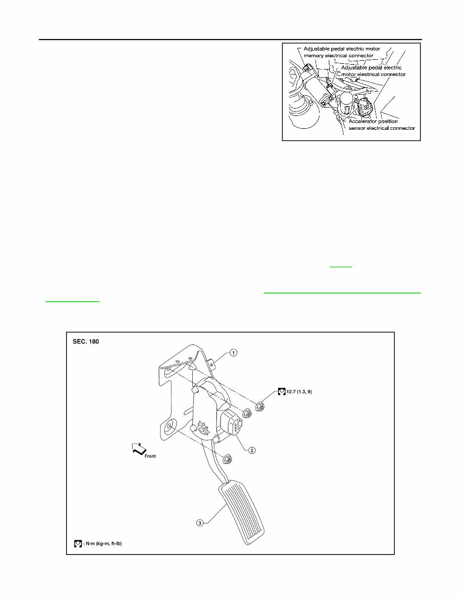
ACC-4 < ON-VEHICLE REPAIR > ACCELERATOR CONTROL SYSTEM 4. Disconnect the adjustable pedal electric motor electrical connec- tor. 5. Disconnect the adjustable pedal electric motor memory electri- cal connector, if equipped. 6. Disconnect the accelerator position sensor electrical connector. 7. Remove the two upper and one lower accelerator pedal nuts. 8. Remove the adjustable accelerator pedal assembly. CAUTION: • Do not disassemble the accelerator pedal assembly. • Do not remove the accelerator pedal position sensor from the accelerator pedal bracket. • Do not disassemble the accelerator pedal adjusting mechanism. • Avoid damage from dropping the accelerator pedal assembly during handling. • Keep the accelerator pedal assembly away from water. Installation Installation is in the reverse order of removal. Inspection After Installation • Check that the accelerator pedal moves smoothly within the specified ranges. • Depress and release the accelerator pedal to check that it returns smoothly to the original released position. • Perform an electrical inspection of the accelerator pedal position sensor. Refer to EC-22 . CAUTION: When the harness connector of the accelerator pedal position sensor is disconnected, perform ″Accelerator Pedal Released Position Learning″. Refer to EC-22, "Accelerator Pedal Released Posi- tion Learning" . NON-ADJUSTABLE ACCELERATOR PEDAL ASSEMBLY Non-Adjustable Accelerator Pedal LBIA0380E Adjustable accelerator pedal – total pedal applied stroke : 48.3 mm (1.90 in) Adjustable accelerator pedal – total pedal adjustment travel : 73.2 mm (2.88 in) LBIA0404E Revision: August 2009 2010 Titan
ACCELERATOR CONTROL SYSTEM ACC-5 < ON-VEHICLE REPAIR > C D E F G H I J K L M A ACC N P O CAUTION: • Do not disassemble the accelerator pedal assembly. • Do not remove the accelerator pedal position sensor from the accelerator pedal bracket. • Avoid damage from dropping the accelerator pedal assembly during handling. • Keep the accelerator pedal assembly away from water. Removal 1. Turn the ignition switch OFF and disconnect the negative battery terminal. 2. Disconnect the accelerator position sensor electrical connector. 3. Remove the two upper and one lower accelerator pedal nuts. 4. Remove the adjustable accelerator pedal assembly. CAUTION: • Do not disassemble the accelerator pedal assembly. • Do not remove the accelerator pedal position sensor from the accelerator pedal bracket. • Avoid damage from dropping the accelerator pedal assembly during handling. • Keep the accelerator pedal assembly away from water. Installation Installation is in the reverse order of removal. Inspection After Installation • Check that the accelerator pedal moves smoothly within the specified range. • Depress and release the accelerator pedal to check that it returns smoothly to the original released position. • Perform an electrical inspection of the accelerator pedal position sensor. Refer to EC-22 . CAUTION: When the harness connector of the accelerator pedal position sensor is disconnected, perform ″Accelerator Pedal Released Position Learning″. Refer to EC-22, "Accelerator Pedal Released Posi- tion Learning" . 1. Non-adjustable accelerator pedal A/T cable attachment bracket (part of the accelerator pedal assembly) 2. Non-adjustable accelerator pedal position sensor (part of the accelerator pedal as- sembly) 3. Non-adjustable accelerator pedal assembly Non-adjustable accelerator pedal – total pedal applied stroke : 48 mm (1.89 in) Revision: August 2009 2010 Titan
You're Reading a Preview
What's Included?
Lifetime Access
Fast Download Speeds
Offline Viewing
Access Contents & Bookmarks
Full Search Facility
Print one or all pages of your manual
$36.99
2010 Nissan Titan Service & Repair Manual Software
The 2010 Nissan Titan Service & Repair Manual is a comprehensive guide for maintaining and repairing various models of the 2010 Nissan Titan, including the S, SV, PRO-4X, and LE models. Whether you're a professional mechanic or a DIY enthusiast, this manual is a valuable resource that provides detailed instructions and diagrams to troubleshoot issues, perform routine maintenance tasks, and complete complex repairs with confidence.
This manual covers a wide range of topics, including engine maintenance, electrical systems, fuel and exhaust systems, transmission, suspension, brakes, body and interior, and much more. Each section is thoroughly explained and illustrated, making it easy to follow along and perform the necessary tasks.
With the 2010 Nissan Titan Service & Repair Manual, you no longer have to rely on expensive dealership visits or guesswork when it comes to maintaining and repairing your vehicle. Save time and money by having all the information you need at your fingertips with this user-friendly manual.
Whether you own the S, SV, PRO-4X, or LE model of the 2010 Nissan Titan, this manual is compatible with all these variants, allowing you to access the specific information you need for your particular vehicle.
Reviews
Q&A
Recently Viewed
5,521,897Happy Clients
2,594,462eManuals
1,120,453Trusted Sellers
15Years in Business
Price:
Actual Price:
2010 Nissan Titan Service & Repair Manual Software





 Lifetime Access




