1990 Nissan 240SX Service & Repair Manual Software
What's Included?
Lifetime Access
Fast Download Speeds
Offline Viewing
Access Contents & Bookmarks
Full Search Facility
Print one or all pages of your manual
2.4L 4-CYL - VINS [F,H,S] 1990 Nissan 240SX 1990 ENGINES Nissan 2.4L 4-Cylinder Axxess, Pickup, Stanza, 240SX * PLEASE READ THIS FIRST * NOTE: For engine repair procedures not covered in this article, see ENGINE OVERHAUL PROCEDURES - GENERAL INFORMATION article in the GENERAL INFORMATION section. ENGINE IDENTIFICATION Engine identification number is stamped on left side of cylinder block between exhaust manifold runners. ENGINE IDENTIFICATION CODES TABLE Application Engine Code VIN Code 2.4L 4-Cylinder Axxess & 240SX ................. KA24E .................. H Pickup ......................... KA24E .................. S Stanza ......................... KA24E .................. F NOTE: If liquid gasket is used on component parts, DO NOT expose gasket to oil or water for at least 30 minutes. VALVE ARRANGEMENT Right Side - All Intake. Left Side - All Exhaust. VALVE CLEARANCE ADJUSTMENT Hydraulic valve lifters are used and no valve adjustment is required. FUEL PRESSURE RELEASE Remove fuel pump fuse. Start engine. After engine stalls, crank engine 2 or 3 times to ensure fuel pressure is released. Turn ignition switch to OFF position and replace fuse. ENGINE R & I AXXESS, STANZA NOTE: For reassembly reference, label all electrical connectors, vacuum hoses and fuel lines before removal. Also place mating marks on engine hood and other major assemblies. Removal 1) Release fuel pressure. See FUEL PRESSURE RELEASE in this
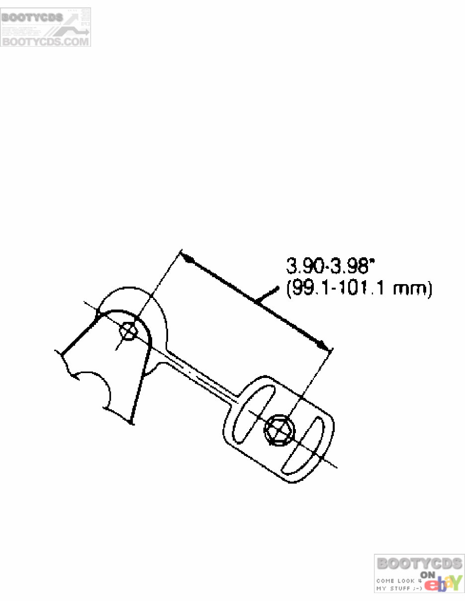
article. Disconnect negative battery cable. Drain oil and coolant. Disconnect all related pipes, electrical harnesses, vacuum lines and fuel lines. Remove A/C compressor and power steering pump without disconnecting hoses and set aside. 2) Remove alternator and adjusting bracket. Raise and support vehicle. Remove drive shaft on 4WD models. On all models, remove axle shafts. Disconnect exhaust manifold from exhaust front pipe. Remove front exhaust pipe. 3) Raise engine slightly and disconnect and/or remove all engine mounts. Support engine and transaxle assembly with jacks under oil pan and transaxle. Lower engine and transaxle assembly. Separate engine from transaxle. Installation On Axxess 4WD models, adjust length between buffer rod bolts. See Fig. 1. On all models, replace worn or separated rubber engine mounts. Ensure proper placement of all electrical harnesses and vacuum lines. To complete installation, reverse removal procedure. See TORQUE SPECIFICATIONS at end of article. Fig. 1: Adjusting Buffer Rod Length (Axxess 4WD) Courtesy of Nissan Motor Co., U.S.A. PICKUP Removal 1) Release fuel pressure. See FUEL PRESSURE RELEASE in this
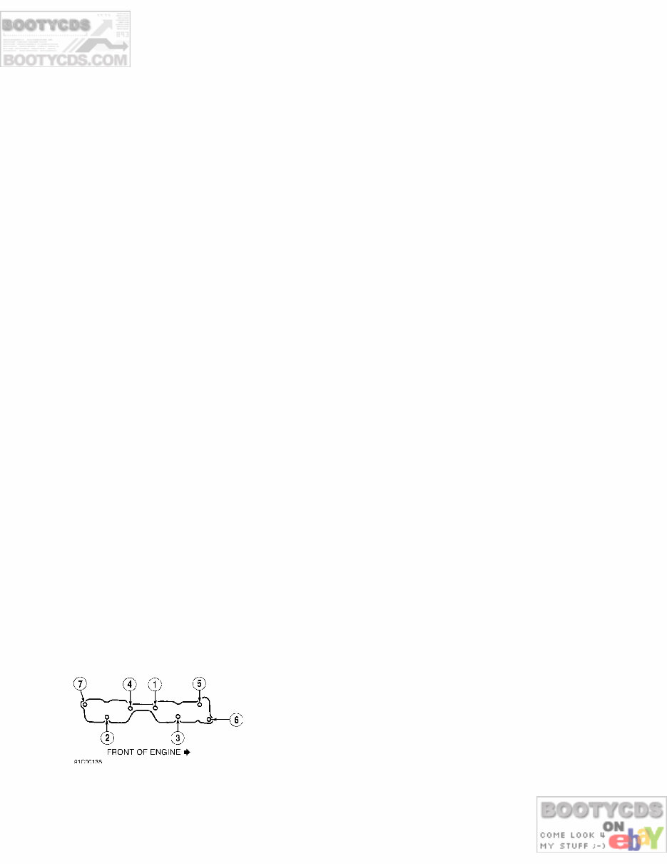
article. Disconnect negative battery cable. Drain oil and coolant. Remove radiator with shroud. Remove cooling fan. 2) Remove engine undercover. Remove A/C compressor and power steering pump (if equipped) without disconnecting hoses and set aside. Wire compressor and pump out of working area. 3) On 2WD models, disconnect starter motor harness. On 4WD models, remove starter motor. On all models, disconnect exhaust manifold from exhaust pipe. Remove front exhaust pipe. 4) On 2WD models, disconnect drive shaft from transmission. Remove transmission-to-rear engine mount bracket bolts. Remove transmission crossmember. Remove front engine mount bolts. Lift and remove engine. 5) On 4WD models, disconnect front drive shaft from front differential carrier. Remove front drive shaft bolts. Remove front differential carrier bolts and remove front differential carrier member. 6) Remove differential front mount bolts. Remove transmission-to-rear engine mount bracket nuts. Remove front engine mount bolts. Lift engine. Remove engine-to-transmission bolts. Lift and remove engine. Installation Replace worn or separated rubber engine mounts. Ensure proper placement of all electrical harnesses and/or vacuum lines. To complete installation, reverse removal procedure. See TORQUE SPECIFICATIONS at end of article. 240SX Removal & Installation Information not available from manufacturer. INTAKE MANIFOLD R & I Removal (All Models) 1) Release fuel pressure. See FUEL PRESSURE RELEASE in this article. Disconnect negative battery cable. Drain coolant. Disconnect throttle cable(s) at throttle body. Disconnect all related pipes, electrical harnesses, vacuum lines and fuel lines. 2) Remove accessories and brackets as required for clearance. Remove intake manifold support bracket. Remove fuel rail and injectors. Remove intake manifold bolts and intake manifold. Installation Install intake manifold on cylinder head. Tighten bolts in sequence to specification. See Fig. 2. See TORQUE SPECIFICATIONS table at end of article. To complete installation, reverse removal procedure. Fig. 2: Intake Manifold Tightening Sequence Courtesy of Nissan Motor Co., U.S.A. EXHAUST MANIFOLD R & I
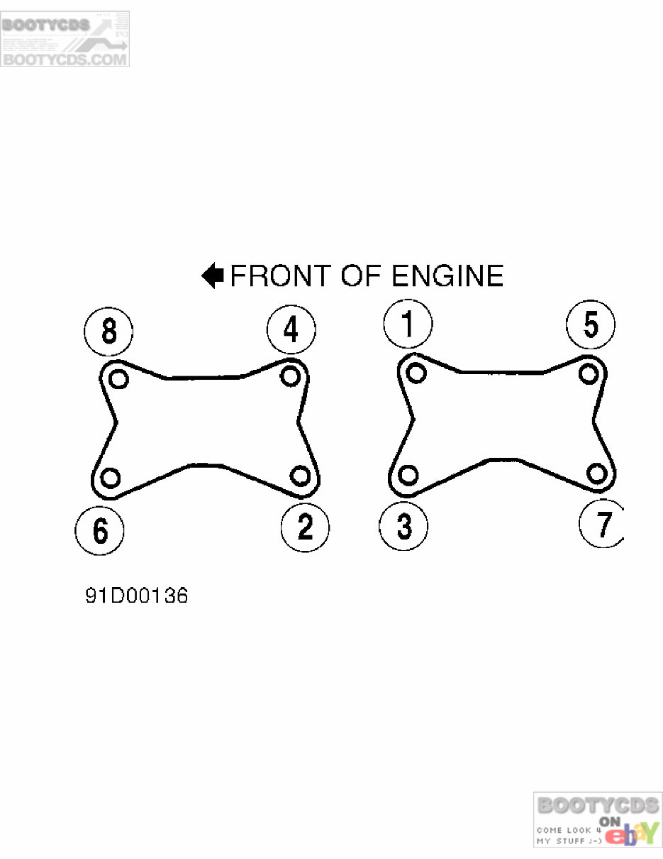
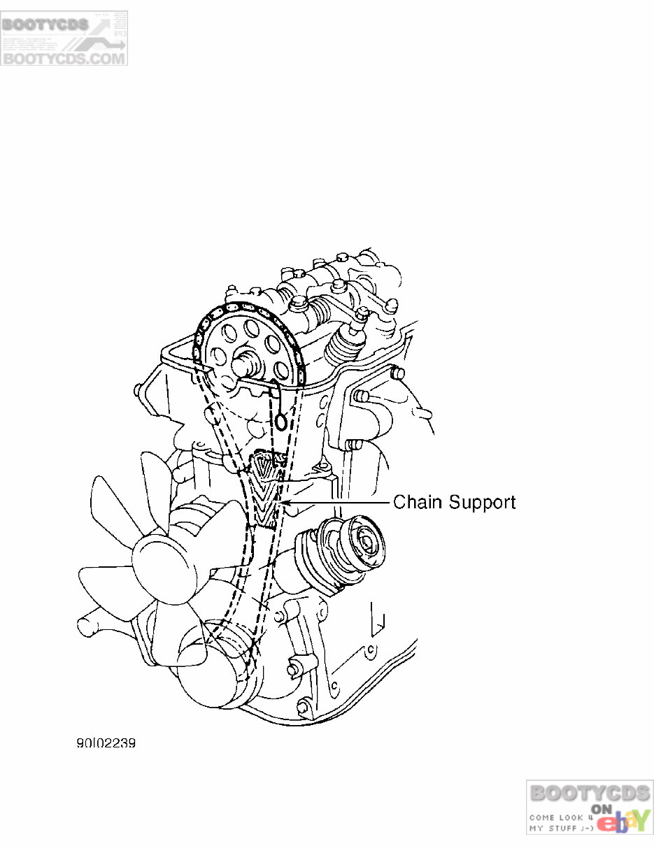
Removal (All Models) Disconnect negative battery cable. Remove accessories and brackets as required for clearance. Disconnect exhaust pipe from manifold. Remove exhaust manifold heat shield and exhaust manifold. Installation Install exhaust manifold on cylinder head. Tighten nuts and bolts in sequence and to specification. See Fig. 3. See TORQUE SPECIFICATIONS table at end of article. To complete installation, reverse removal procedure. Fig. 3: Exhaust Manifold Tightening Sequence Courtesy of Nissan Motor Co., U.S.A. CYLINDER HEAD R & I AXXESS, STANZA Removal 1) Release fuel pressure. See FUEL PRESSURE RELEASE in this article. Disconnect negative battery cable. Drain coolant. Remove intake air duct. Disconnect throttle cable(s) at throttle body. 2) Remove throttle body and intake plenum as a unit. Disconnect all related pipes, hoses, fuel lines and vacuum lines. Remove intake manifold support bracket and intake manifold. Remove rocker arm cover. Carefully remove rocker arm cover without striking rocker arms. 3) Set No. 1 piston at TDC on compression stroke. Loosen camshaft sprocket bolt. Using Chain Support (KV10105800), support timing chain. See Fig. 4. Remove camshaft sprocket.
4) Remove cylinder head-to-front cover bolts. Remove cylinder head bolts in REVERSE order of tightening sequence in 2 or 3 steps. See Fig. 5. Remove cylinder head. Disassembly Loosen rocker arm shaft bolts evenly in 2 or 3 steps, rotating from outside to inside in sequence. Remove camshaft. Remove valves, valve springs and related parts using Valve Spring Compressor (KV10109210). Mark bottom side of springs with Red paint if necessary for reassembly reference. Fig. 4: Holding Timing Chain With Chain Support Courtesy of Nissan Motor Co., U.S.A. Inspection 1) Check cylinder head for cracks, flaws or damage. Repair or
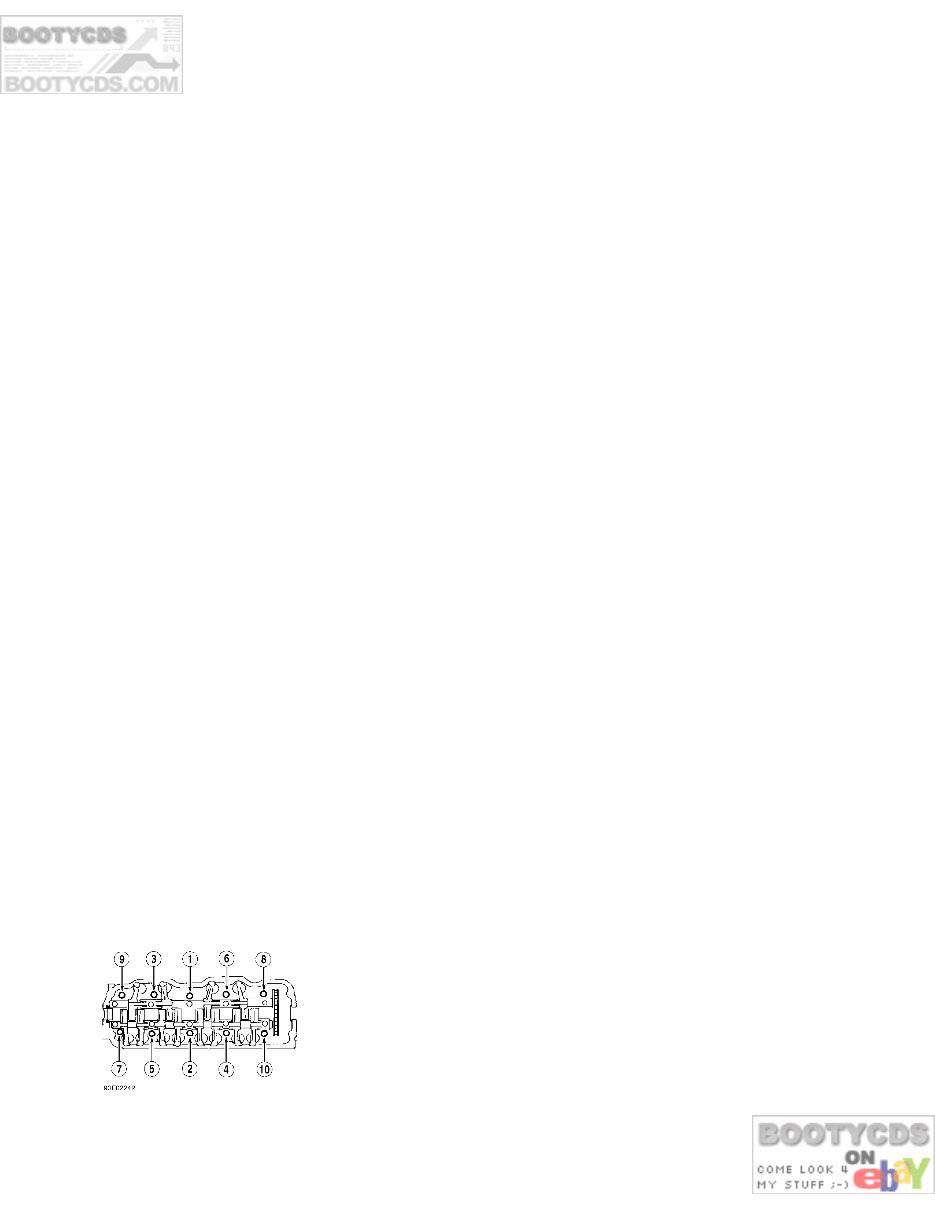
replace as necessary. Inspect head and block mating surfaces for warpage. Warpage limit is .004" (.10 mm) or less. If beyond limit, refinish surface. 2) Maximum surface grinding limit of cylinder head plus block is .008" (.20 mm). Replace head and/or block if machined or warped beyond specification. 3) Using calipers, measure cylinder head height. See CYLINDER HEAD SPECS TABLE at end of article. If cylinder head height is not within specifications, replace cylinder head. 4) After resurfacing cylinder head, ensure camshaft rotates freely by hand. Replace cylinder head if resistance is felt. Installation 1) Ensure mating surfaces of cylinder head and block are clean. Install cylinder head and new gasket. 2) Tighten head bolts to 22 ft. lbs. (30 N.m). See Fig. 5. Tighten head bolts to 58 ft. lbs. (79 N.m). Loosen all bolts completely. Tighten head bolts to 22 ft. lbs. (30 N.m). Tighten head bolts to 54-61 ft. lbs. (73-83 N.m). 3) Ensure knockpin is positioned at 12 o’clock in camshaft. Set chain on camshaft by aligning Silver chain mating link to punch mark on cam sprocket. Install camshaft sprocket to camshaft. Install camshaft sprocket bolt and tighten to specification. Remove chain stopper installed during removal. 4) Apply sealant to cylinder head and rubber plug. Install rubber plug. Wipe off excess sealant. To complete installation, reverse removal procedure. Run engine for several minutes, allow engine to cool down and recheck head bolt torque. PICKUP, 240SX Removal 1) Release fuel pressure. See FUEL PRESSURE RELEASE in this article. Disconnect negative battery cable. Drain cooling system. Remove power steering pump drive belt. Remove power steering pump, brackets and idler pulley. 2) Label and disconnect necessary electrical wiring and vacuum hoses. Disconnect accelerator cable bracket. Disconnect EGR tube from exhaust manifold. Remove intake plenum-to-intake manifold bolts. 3) Remove intake manifold-to-cylinder head bolts while raising plenum upward. Remove rocker arm cover. Bring No. 1 piston to TDC on compression stroke. Loosen camshaft sprocket bolt. Using Chain Support (KV10105800), support timing chain. See Fig. 4. Remove camshaft sprocket. 4) Remove cylinder head-to-engine front cover bolts. Loosen cylinder head bolts in 2 or 3 steps in reverse order of tightening sequence to prevent warping or cracking cylinder head. See Fig. 5. Remove cylinder head. Fig. 5: Cylinder Head Tightening Sequence Courtesy of Nissan Motor Co., U.S.A. Disassembly
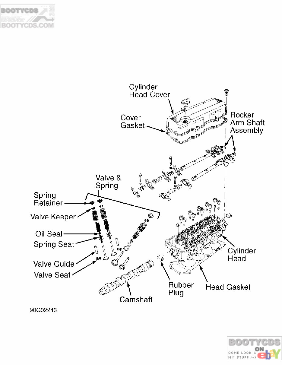
Loosen rocker arm shaft bolts evenly in 2 or 3 steps, rotating from outside to inside in sequence. Remove camshaft. Remove valves, valve springs and related parts using Valve Spring Compressor (KV10109210). Mark bottom side of springs with Red paint if necessary for reassembly reference. Fig. 6: Exploded View of Cylinder Head Courtesy of Nissan Motor Co., U.S.A. Inspection 1) Check cylinder head for cracks, flaws or damage. Repair or replace as necessary. Inspect head and block mating surfaces for warpage. Warpage limit is .004" (.10 mm) or less. If beyond limit,
refinish surface. 2) Maximum surface grinding limit of cylinder head plus block is .008" (.20 mm). Replace head and/or block if machined or warped beyond specification. 3) Using calipers, measure cylinder head height. See CYLINDER HEAD SPECS TABLE at end of article. If cylinder head height is not within specifications, replace cylinder head. 4) After resurfacing cylinder head, ensure camshaft rotates freely by hand. Replace cylinder head if resistance is felt. Installation 1) Ensure mating surfaces of cylinder head and block are clean. Install cylinder head and new gasket. 2) Tighten head bolts to 22 ft. lbs. (30 N.m). See Fig. 5. Tighten head bolts to 58 ft. lbs. (79 N.m). Loosen all bolts completely. Tighten head bolts to 22 ft. lbs. (30 N.m). Tighten head bolts to 54-61 ft. lbs. (73-83 N.m). 3) Ensure knockpin is positioned at 12 o’clock in camshaft. Set chain on camshaft by aligning Silver chain mating link to punch mark on cam sprocket. Install camshaft sprocket to camshaft. Install camshaft sprocket bolt and tighten to specification. Remove chain stopper installed during removal. 4) Apply sealant to cylinder head and rubber plug. Install rubber plug. Wipe off excess sealant. To complete installation, reverse removal procedure. Run engine for several minutes, allow engine to cool down and recheck head bolt torque. FRONT COVER & OIL SEAL R & I NOTE: The following procedure includes removal of engine front cover. If only oil seal is being replaced, it is not necessary to remove front cover. Removal 1) Drain coolant and crankcase oil. Remove radiator and cooling fan. Remove air cleaner. Label all wiring and vacuum lines for reassembly reference. 2) Remove power steering, air conditioner and alternator belts. On Pickup and 240SX, remove distributor cap and wiring from distributor. Set No. 1 piston to TDC of compression stroke. Ensure distributor rotor is pointing to No. 1 spark plug wire on distributor cap. 3) On all models, remove power steering pump, power steering idler pulley and power steering brackets (if equipped). Remove alternator and adjusting bracket. Remove compressor idler pulley and crankshaft pulley. On Pickup and 240SX, remove oil pump together with pump drive spindle. 4) On all models, remove rocker arm cover. Remove oil pan. See OIL PAN R & I in this article. On Axxess and Stanza, remove engine mount at front of engine near alternator. 5) On all models, remove front cover bolts. Note bolt locations for reassembly reference. Remove front cover together with distributor (Pickup and 240SX) and water pump. DO NOT damage head gasket. Disassemble as necessary. Inspection Check oil seal surface of crankshaft for nicks or damage. Repair as necessary. Installation 1) Before installation, apply sealant at mating corners of oil pan gasket, cylinder head gasket and front cover gaskets. Press
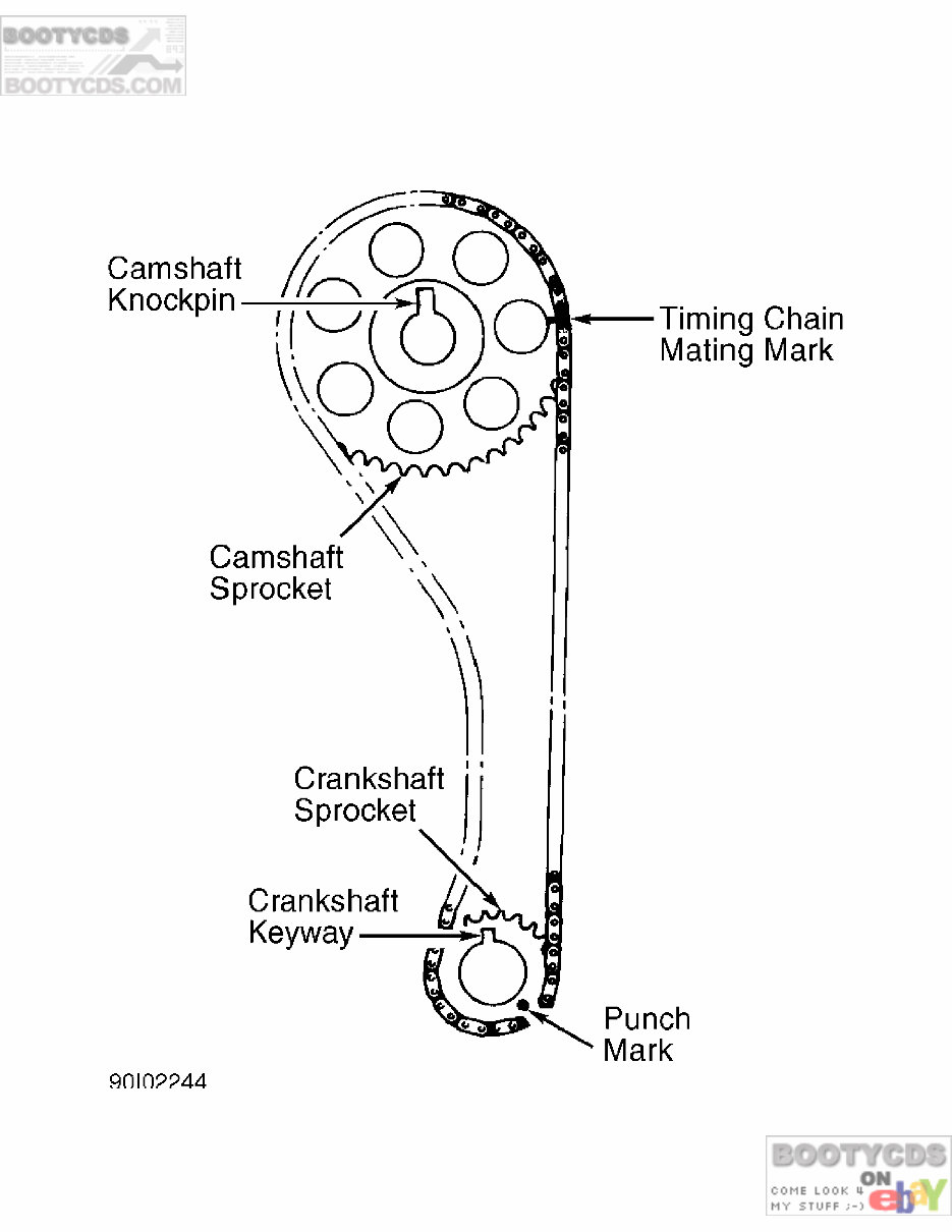
new oil seal in front cover with dust seal lip facing outside. 2) Apply lithium grease to oil seal sealing lip before cover is installed. Use new gaskets and sealant. Front cover mount bolts are different lengths. Ensure bolts are in proper locations during installation. Install front cover. To complete installation, reverse removal procedure. TIMING CHAIN R & I Removal 1) Remove front cover. See FRONT COVER & OIL SEAL R & I in this article. Carefully remove chain tensioner. DO NOT lose spring. Remove chain guides. Remove camshaft sprocket bolt, ensuring camshaft does not rotate. CAUTION: Ensure neither crankshaft nor camshaft is rotated with timing chain off or damage to valves may result. 2) Remove timing chain and camshaft sprocket. Remove oil slinger (if equipped). On Pickup and 240SX, remove oil pump drive gear (note installation direction). On Axxess and Stanza remove oil pump drive boss. On all models, remove crankshaft sprocket. Remove chain guide and tensioner. Inspection 1) Check camshaft sprocket tooth surface for flaws and wear. Replace if damaged. Install sprocket on camshaft and check for runout. See CAMSHAFT SPECS TABLE at end of article. Sprocket runout limit using total indicator reading is .004" (.10 mm). Replace sprocket, if runout exceeds specification. 2) Check timing chain for damage and excessive wear at roller links. Replace timing chain if faulty or stretched. Check chain tensioner and guide for excessive wear or defect. Replace as necessary. Installation 1) Ensure No. 1 piston is at TDC of compression stroke. Camshaft knockpin should be at 12 o’clock position. Align Silver timing chain link with punch mark on sprocket. 2) Install timing chain onto crankshaft sprocket. Align marks on timing chain with marks on crankshaft sprocket. See Fig. 7. Both sprocket timing marks will be toward left side of engine. Install chain guide and tensioner. Adjust chain guide tensioner. 3) Install oil pump drive gear onto crankshaft with large chamfered inner face toward rear. Install oil slinger (if equipped). To complete installation, reverse removal procedure.
Fig. 7: Aligning Timing Chain on Crankshaft & Camshaft Courtesy of Nissan Motor Co., U.S.A. ROCKER ARM & SHAFT R & I
If you are in need of a repair manual for your 1990 Nissan 240SX, look no further. Our comprehensive repair manual software is now available in a convenient digital format, making it an ideal resource for both professional mechanics and DIY enthusiasts.
Gone are the days of relying on traditional paper manuals, which can be costly and cumbersome. Our accessible repair manual software covers all aspects of the Nissan 240SX, providing you with the necessary information to tackle various repairs and maintenance tasks.
Whether you are looking to address brake issues, replace suspension components, troubleshoot engine problems, or perform standard maintenance, this repair manual software has got you covered. It encompasses a wide range of service information, including brakes, engine, suspension, steering, drivetrain, electrical systems, heating, and air conditioning.
By utilizing this manual, you can potentially save a significant amount of money on vehicle repairs. Professional mechanics often charge high fees for their services, making a DIY approach with the assistance of our 1990 Nissan 240SX repair manual software a cost-effective alternative.
Our software is designed for ease of use and is compatible with Windows, Mac computers, smartphones, and tablets, ensuring accessibility across various devices.
Recently Viewed
5,521,897Happy Clients
2,594,462eManuals
1,120,453Trusted Sellers
15Years in Business
Price:
Actual Price:
1990 Nissan 240SX Service & Repair Manual Software