HAC-1 VENTILATION, HEATER & AIR CONDITIONER C D E F G H J K L M SECTION HAC A B HAC N O P CONTENTS HEATER & AIR CONDITIONING CONTROL SYSTEM AUTOMATIC AIR CONDITIONER PRECAUTION .............................................. 5 PRECAUTIONS .................................................. 5 Precaution for Supplemental Restraint System (SRS) "AIR BAG" and "SEAT BELT PRE-TEN- SIONER" .................................................................. 5 Precaution for Work ................................................. 5 Working with HFC-134a (R-134a) ............................ 5 Precaution for Service Equipment ............................ 6 PREPARATION ........................................... 8 PREPARATION .................................................. 8 Special Service Tool ................................................ 8 Commercial Service Tool ......................................... 8 SYSTEM DESCRIPTION ............................. 9 COMPONENT PARTS ....................................... 9 Component Part Location ........................................ 9 Component Description .......................................... 10 SYSTEM ............................................................12 System Diagram ..................................................... 12 System Description ................................................ 12 Air Flow Control ...................................................... 13 Air Inlet Control ...................................................... 14 Air Outlet Control .................................................... 15 Compressor Control ............................................... 15 Door Control ........................................................... 15 Temperature Control .............................................. 20 Fail-safe ................................................................. 20 OPERATION ......................................................21 Switch Name and Function .................................... 21 DIAGNOSIS SYSTEM (A/C AUTO AMP.) ........24 Description ............................................................. 24 CONSULT Function (HVAC) .................................. 24 DIAGNOSIS SYSTEM (BCM) ........................... 28 COMMON ITEM ........................................................28 COMMON ITEM : CONSULT Function (BCM - COMMON ITEM) ....................................................28 AIR CONDITIONER ..................................................29 AIR CONDITIONER : CONSULT Function (BCM - AIR CONDITIONER) ..............................................29 DIAGNOSIS SYSTEM (IPDM E/R) ................... 30 Diagnosis Description .............................................30 CONSULT Function (IPDM E/R) ............................31 ECU DIAGNOSIS INFORMATION ............. 34 A/C AUTO AMP. ............................................... 34 Reference Value .....................................................34 DTC Inspection Priority Chart ..............................38 DTC Index ..............................................................38 ECM, IPDM E/R, BCM ....................................... 40 List of ECU Reference ............................................40 WIRING DIAGRAM ..................................... 41 AUTOMATIC AIR CONDITIONING SYSTEM ... 41 Wiring Diagram .......................................................41 BASIC INSPECTION .................................. 51 DIAGNOSIS AND REPAIR WORKFLOW ........ 51 Work Flow ...............................................................51 OPERATION INSPECTION .............................. 53 Work Procedure ......................................................53 SYSTEM SETTING ........................................... 55 Temperature Setting Trimmer ................................55 Inlet Port Memory Function (FRE) ..........................55 Inlet Port Memory Function (REC) .........................56 Target Evaporator Temp Upper Limit .....................56 Revision: December 2014 2015 Sentra NAM
HAC-2 DOOR MOTOR STARTING POSITION RE- SET ................................................................... 57 Description ............................................................. 57 Work Procedure ..................................................... 57 DTC/CIRCUIT DIAGNOSIS ........................ 58 U1000 CAN COMM CIRCUIT ........................... 58 Description ............................................................. 58 DTC Logic .............................................................. 58 Diagnosis Procedure ............................................. 58 U1010 CONTROL UNIT (CAN) ........................ 59 Description ............................................................. 59 DTC Logic .............................................................. 59 Diagnosis Procedure ............................................. 59 B2578, B2579 IN-VEHICLE SENSOR .............. 60 DTC Logic .............................................................. 60 Diagnosis Procedure ............................................. 60 Component Inspection ........................................... 61 B257B, B257C AMBIENT SENSOR ................ 63 DTC Logic .............................................................. 63 Diagnosis Procedure ............................................. 63 Component Inspection ........................................... 64 B2581, B2582 INTAKE SENSOR ..................... 66 DTC Logic .............................................................. 66 Diagnosis Procedure ............................................. 66 Component Inspection ........................................... 67 B2630, B2631 SUNLOAD SENSOR ................ 69 DTC Logic .............................................................. 69 Diagnosis Procedure ............................................. 69 Component Inspection ........................................... 70 B27A2, B27A3, B27A4, B27A5 AIR MIX DOOR MOTOR (DRIVER SIDE) ....................... 72 DTC Logic .............................................................. 72 Diagnosis Procedure ............................................. 72 Component Inspection ........................................... 73 B27AA, B27AB, B27AC, B27AD AIR MIX DOOR MOTOR (PASSENGER SIDE) .............. 74 DTC Logic .............................................................. 74 Diagnosis Procedure ............................................. 74 Component Inspection ........................................... 75 B27A6, B27A7, B27A8, B27A9 MODE DOOR MOTOR ............................................................. 77 DTC Logic .............................................................. 77 Diagnosis Procedure ............................................. 77 Component Inspection ........................................... 78 B27A0, B27A1 INTAKE DOOR MOTOR ......... 79 DTC Logic .............................................................. 79 Diagnosis Procedure ............................................. 79 Component Inspection (PBR) ................................ 81 Component Inspection (Motor) .............................. 82 POWER SUPPLY AND GROUND CIRCUIT .... 83 A/C AUTO AMP. ....................................................... 83 A/C AUTO AMP. : Diagnosis Procedure ................ 83 A/C SWITCH ASSEMBLY ........................................ 83 A/C SWITCH ASSEMBLY : Component Function Check ..................................................................... 83 A/C SWITCH ASSEMBLY : Diagnosis Procedure ... 84 A/C SWITCH ASSEMBLY SIGNAL CIRCUIT ... 85 Diagnosis Procedure .............................................. 85 A/C ON SIGNAL ............................................... 86 Component Function Check .................................. 86 Diagnosis Procedure .............................................. 86 BLOWER FAN ON SIGNAL ............................. 88 Component Function Check .................................. 88 Diagnosis Procedure .............................................. 88 BLOWER MOTOR ............................................ 90 Diagnosis Procedure .............................................. 90 Component Inspection (Blower Motor) .................. 92 Component Inspection (Blower Motor Relay) ........ 93 MAGNET CLUTCH ........................................... 94 Component Function Check .................................. 94 Diagnosis Procedure .............................................. 94 ECV (ELECTRICAL CONTROL VALVE) ......... 95 Diagnosis Procedure .............................................. 95 Component Inspection ........................................... 96 SYMPTOM DIAGNOSIS ............................ 97 HEATER AND AIR CONDITIONING SYSTEM CONTROL SYMPTOMS ................................... 97 Diagnosis Chart By Symptom ................................ 97 INSUFFICIENT COOLING ................................ 99 Description ............................................................. 99 Diagnosis Procedure .............................................. 99 INSUFFICIENT HEATING ............................... 101 Description ........................................................... 101 Diagnosis Procedure ............................................ 101 COMPRESSOR DOES NOT OPERATE ......... 102 Description ........................................................... 102 Diagnosis Procedure ............................................ 102 REMOVAL AND INSTALLATION ............. 104 A/C SWITCH ASSEMBLY ............................... 104 Removal and Installation ...................................... 104 A/C AUTO AMP. .............................................. 105 Exploded View ..................................................... 105 Removal and Installation ...................................... 105 AMBIENT SENSOR ......................................... 106 Removal and Installation ...................................... 106 Revision: December 2014 2015 Sentra NAM
HAC-3 C D E F G H J K L M A B HAC N O P IN-VEHICLE SENSOR .................................... 107 Removal and Installation ...................................... 107 SUNLOAD SENSOR ....................................... 108 Removal and Installation ...................................... 108 INTAKE SENSOR ........................................... 109 Removal and Installation ...................................... 109 REFRIGERANT PRESSURE SENSOR .......... 110 Removal and Installation ...................................... 110 DOOR MOTOR ................................................ 111 Exploded View ..................................................... 111 INTAKE DOOR MOTOR ......................................... 112 INTAKE DOOR MOTOR : Removal and Installa- tion ....................................................................... 112 MODE DOOR MOTOR ........................................... 112 MODE DOOR MOTOR : Removal and Installation .. 112 AIR MIX DOOR MOTOR ........................................ 112 AIR MIX DOOR MOTOR : Removal and Installa- tion - Air Mix Door Motor RH ................................ 112 AIR MIX DOOR MOTOR : Removal and Installa- tion - Air Mix Door Motor LH ................................. 112 POWER TRANSISTOR ................................... 113 Removal and Installation ...................................... 113 MANUAL AIR CONDITIONER PRECAUTION ........................................... 114 PRECAUTIONS ............................................... 114 Precaution for Supplemental Restraint System (SRS) "AIR BAG" and "SEAT BELT PRE-TEN- SIONER" .............................................................. 114 Precaution for Work ............................................. 114 Working with HFC-134a (R-134a) ........................ 114 Precaution for Service Equipment ........................ 115 PREPARATION ........................................ 117 PREPARATION ............................................... 117 Special Service Tool ............................................ 117 Commercial Service Tool ..................................... 117 SYSTEM DESCRIPTION .......................... 118 COMPONENT PARTS .................................... 118 Component Part Location .................................... 118 Component Description ........................................ 119 SYSTEM .......................................................... 121 System Diagram ................................................... 121 System Description .............................................. 121 Air Flow Control .................................................... 122 Air Inlet Control .................................................... 122 Air Outlet Control .................................................. 122 Compressor Control ............................................. 122 Door Control ......................................................... 123 Temperature Control ............................................ 126 OPERATION ................................................... 127 Switch Name and Function ................................... 127 DIAGNOSIS SYSTEM (BCM) (WITH INTELLI- GENT KEY SYSTEM) ..................................... 129 COMMON ITEM ...................................................... 129 COMMON ITEM : CONSULT Function (BCM - COMMON ITEM) .................................................. 129 AIR CONDITIONER ................................................ 130 AIR CONDITIONER : CONSULT Function (BCM - AIR CONDITIONER) ............................................ 130 DIAGNOSIS SYSTEM (BCM) (WITHOUT IN- TELLIGENT KEY SYSTEM) ........................... 131 COMMON ITEM ...................................................... 131 COMMON ITEM : CONSULT Function (BCM - COMMON ITEM) .................................................. 131 AIR CONDITIONER ................................................ 132 AIR CONDITIONER : CONSULT Function (BCM - AIR CONDITIONER) ............................................ 132 DIAGNOSIS SYSTEM (IPDM E/R) (WITH IN- TELLIGENT KEY SYSTEM) ........................... 133 Diagnosis Description ........................................... 133 CONSULT Function (IPDM E/R) .......................... 134 DIAGNOSIS SYSTEM (IPDM E/R) (WITHOUT INTELLIGENT KEY SYSTEM) ........................ 137 Diagnosis Description ........................................... 137 CONSULT Function (IPDM E/R) .......................... 138 ECU DIAGNOSIS INFORMATION ........... 141 A/C AUTO AMP. ............................................. 141 Reference Value ................................................... 141 ECM, IPDM E/R, BCM ..................................... 144 List of ECU Reference .......................................... 144 WIRING DIAGRAM ................................... 145 MANUAL AIR CONDITIONING SYSTEM ....... 145 Wiring Diagram ..................................................... 145 MANUAL HEATER SYSTEM .......................... 152 Wiring Diagram ..................................................... 152 BASIC INSPECTION ................................ 156 DIAGNOSIS AND REPAIR WORKFLOW ...... 156 Work Flow ............................................................. 156 OPERATION INSPECTION ............................ 157 Work Procedure .................................................... 157 DTC/CIRCUIT DIAGNOSIS ...................... 159 Revision: December 2014 2015 Sentra NAM
HAC-4 POWER SUPPLY AND GROUND CIRCUIT .. 159 A/C AUTO AMP. ..................................................... 159 A/C AUTO AMP. : Diagnosis Procedure .............. 159 A/C SWITCH ASSEMBLY ...................................... 159 A/C SWITCH ASSEMBLY : Component Function Check ................................................................... 159 A/C SWITCH ASSEMBLY : Diagnosis Procedure .. 160 MODE DOOR MOTOR ................................... 161 Diagnosis Procedure ............................................ 161 Component Inspection .......................................... 162 AIR MIX DOOR MOTOR ................................. 163 Diagnosis Procedure ............................................ 163 Component Inspection .......................................... 164 INTAKE DOOR MOTOR ................................. 165 Diagnosis Procedure ............................................ 165 Component Inspection (Motor) ............................. 166 A/C SWITCH ASSEMBLY SIGNAL CIRCUIT . 167 Diagnosis Procedure ............................................ 167 A/C ON SIGNAL ............................................. 168 Component Function Check ................................. 168 Diagnosis Procedure ............................................ 168 INTAKE SENSOR ........................................... 170 Diagnosis Procedure ............................................ 170 Component Inspection .......................................... 171 BLOWER FAN ON SIGNAL ........................... 172 Component Function Check ................................. 172 Diagnosis Procedure ............................................ 172 BLOWER MOTOR .......................................... 174 Diagnosis Procedure ............................................ 174 Component Inspection (Blower Motor) ................. 176 Component Inspection (Blower Motor Relay) ....... 177 MAGNET CLUTCH ......................................... 178 Component Function Check ................................. 178 Diagnosis Procedure ............................................ 178 ECV (ELECTRICAL CONTROL VALVE) ....... 179 Diagnosis Procedure ............................................ 179 Component Inspection .......................................... 180 SYMPTOM DIAGNOSIS ........................... 181 HEATER AND AIR CONDITIONING SYSTEM CONTROL SYMPTOMS .................................. 181 Symptom Table .................................................... 181 INSUFFICIENT COOLING ............................... 182 Component Function Check ................................ 182 INSUFFICIENT HEATING ............................... 184 Component Function Check ................................ 184 COMPRESSOR DOES NOT OPERATE ......... 186 Description ........................................................... 186 Diagnosis Procedure ............................................ 186 REMOVAL AND INSTALLATION ............. 188 A/C ASSEMBLY SWITCH ............................... 188 Removal and Installation ...................................... 188 A/C AUTO AMP. .............................................. 189 Exploded View ..................................................... 189 Removal and Installation ...................................... 189 INTAKE SENSOR ............................................ 190 Removal and Installation ...................................... 190 REFRIGERANT PRESSURE SENSOR .......... 191 Removal and Installation ...................................... 191 DOOR MOTOR ................................................ 192 Exploded View ..................................................... 192 INTAKE DOOR MOTOR ........................................ 193 INTAKE DOOR MOTOR : Removal and Installa- tion ....................................................................... 193 MODE DOOR MOTOR ........................................... 193 MODE DOOR MOTOR : Removal and Installation . 193 AIR MIX DOOR MOTOR ........................................ 193 AIR MIX DOOR MOTOR : Removal and Installa- tion ....................................................................... 193 BLOWER MOTOR RESISTOR ....................... 194 Removal and Installation ...................................... 194 Revision: December 2014 2015 Sentra NAM
PRECAUTIONS HAC-5 < PRECAUTION > [AUTOMATIC AIR CONDITIONER] C D E F G H J K L M A B HAC N O P PRECAUTION PRECAUTIONS Precaution for Supplemental Restraint System (SRS) "AIR BAG" and "SEAT BELT PRE-TENSIONER" INFOID:0000000011538352 The Supplemental Restraint System such as “AIR BAG” and “SEAT BELT PRE-TENSIONER”, used along with a front seat belt, helps to reduce the risk or severity of injury to the driver and front passenger for certain types of collision. Information necessary to service the system safely is included in the SR and SB section of this Service Manual. WARNING: • To avoid rendering the SRS inoperative, which could increase the risk of personal injury or death in the event of a collision which would result in air bag inflation, all maintenance must be performed by an authorized NISSAN/INFINITI dealer. • Improper maintenance, including incorrect removal and installation of the SRS, can lead to personal injury caused by unintentional activation of the system. For removal of Spiral Cable and Air Bag Module, see the SR section. • Do not use electrical test equipment on any circuit related to the SRS unless instructed to in this Service Manual. SRS wiring harnesses can be identified by yellow and/or orange harnesses or har- ness connectors. PRECAUTIONS WHEN USING POWER TOOLS (AIR OR ELECTRIC) AND HAMMERS WARNING: • When working near the Airbag Diagnosis Sensor Unit or other Airbag System sensors with the Igni- tion ON or engine running, DO NOT use air or electric power tools or strike near the sensor(s) with a hammer. Heavy vibration could activate the sensor(s) and deploy the air bag(s), possibly causing serious injury. • When using air or electric power tools or hammers, always switch the Ignition OFF, disconnect the battery and wait at least three minutes before performing any service. Precaution for Work INFOID:0000000011538353 • When removing or disassembling each component, be careful not to damage or deform it. If a component may be subject to interference, be sure to protect it with a shop cloth. • When removing (disengaging) components with a screwdriver or similar tool, be sure to wrap the component with a shop cloth or vinyl tape to protect it. • Protect the removed parts with a shop cloth and prevent them from being dropped. • Replace a deformed or damaged clip. • If a part is specified as a non-reusable part, always replace it with a new one. • Be sure to tighten bolts and nuts securely to the specified torque. • After installation is complete, be sure to check that each part works properly. • Follow the steps below to clean components: - Water soluble dirt: • Dip a soft cloth into lukewarm water, wring the water out of the cloth and wipe the dirty area. • Then rub with a soft, dry cloth. - Oily dirt: • Dip a soft cloth into lukewarm water with mild detergent (concentration: within 2 to 3%) and wipe the dirty area. • Then dip a cloth into fresh water, wring the water out of the cloth and wipe the detergent off. • Then rub with a soft, dry cloth. - Do not use organic solvent such as thinner, benzene, alcohol or gasoline. - For genuine leather seats, use a genuine leather seat cleaner. Working with HFC-134a (R-134a) INFOID:0000000011538354 WARNING: • CFC-12 (R-12) refrigerant and HFC-134a (R-134a) refrigerant are not compatible. If the refrigerants are mixed compressor failure is likely to occur. Refer to HA-25, "Inspection" . To determine the purity of HFC-134a (R-134a) in the vehicle and recovery tank, use Refrigerant Recovery/Recycling Recharg- ing equipment and Refrigerant Identifier. Revision: December 2014 2015 Sentra NAM
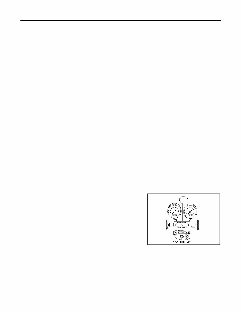
HAC-6 < PRECAUTION > [AUTOMATIC AIR CONDITIONER] PRECAUTIONS • Use only specified oil for the HFC-134a (R-134a) A/C system and HFC-134a (R-134a) components. If oil other than that specified is used, compressor failure is likely to occur. • The specified HFC-134a (R-134a) oil rapidly absorbs moisture from the atmosphere. The following handling precautions must be observed: - When removing refrigerant components from a vehicle, immediately cap (seal) the component to minimize the entry of moisture from the atmosphere. - When installing refrigerant components to a vehicle, do not remove the caps (unseal) until just before connecting the components. Connect all refrigerant loop components as quickly as possible to minimize the entry of moisture into system. - Only use the specified oil from a sealed container. Immediately reseal containers of oil. Without proper sealing, oil will become moisture saturated and should not be used. - Avoid breathing A/C refrigerant and oil vapor or mist. Exposure may irritate eyes, nose and throat. Remove HFC-134a (R-134a) from the A/C system using certified service equipment meeting require- ments of SAE J2210 [HFC-134a (R-134a) recycling equipment], or J2209 [HFC-134a (R-134a) recy- cling equipment], If accidental system discharge occurs, ventilate work area before resuming service. Additional health and safety information may be obtained from refrigerant and oil manufac- turers. - Do not allow A/C oil to come in contact with styrofoam parts. Damage may result. CONTAMINATED REFRIGERANT If a refrigerant other than pure HFC-134a (R-134a) is identified in a vehicle, your options are: • Explain to the customer that environmental regulations prohibit the release of contaminated refrigerant into the atmosphere. • Explain that recovery of the contaminated refrigerant could damage your service equipment and refrigerant supply. • Suggest the customer return the vehicle to the location of previous service where the contamination may have occurred. • If you choose to perform the repair, recover the refrigerant using only dedicated equipment and contain- ers. Do not recover contaminated refrigerant into your existing service equipment. If your facility does not have dedicated recovery equipment, you may contact a local refrigerant product retailer for available ser- vice. This refrigerant must be disposed of in accordance with all federal and local regulations. In addition, replacement of all refrigerant system components on the vehicle is recommended. • If the vehicle is within the warranty period, the air conditioner warranty is void. Please contact NISSAN Cus- tomer Affairs for further assistance. Precaution for Service Equipment INFOID:0000000011538355 MANIFOLD GAUGE SET Be certain that the gauge face indicates R-134a or 134a. Make sure the gauge set has 1/2″-16 ACME threaded connections for service hoses. Confirm the set has been used only with refrigerant HFC- 134a (R-134a) along with specified oil. SERVICE HOSES SHA533D Revision: December 2014 2015 Sentra NAM
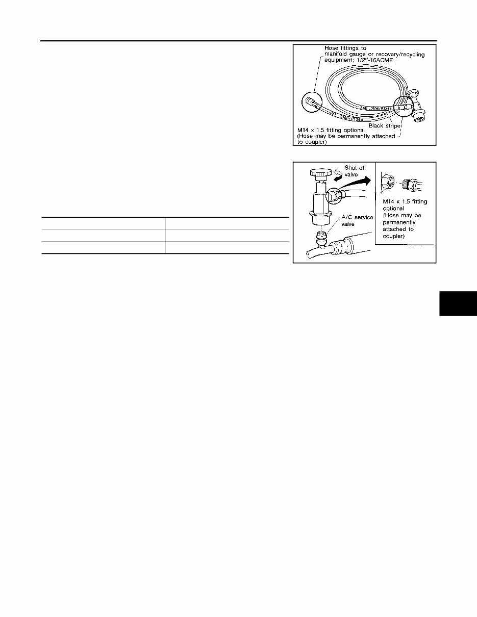
PRECAUTIONS HAC-7 < PRECAUTION > [AUTOMATIC AIR CONDITIONER] C D E F G H J K L M A B HAC N O P Be certain that the service hoses display the markings described (colored hose with black stripe). All hoses must include positive shut- off devices (either manual or automatic) near the end of the hoses opposite the manifold gauge. SERVICE COUPLERS Do not attempt to connect HFC-134a (R-134a) service couplers to a CFC-12 (R-12) A/C system. The HFC-134a (R-134a) couplers will not properly connect to the CFC-12 (R-12) system. However, if an improper connection is attempted, discharging and contamination may occur. RHA272D Shut-off valve rotation A/C service valve Clockwise Open Counterclockwise Close RHA273D Revision: December 2014 2015 Sentra NAM
HAC-8 < PREPARATION > [AUTOMATIC AIR CONDITIONER] PREPARATION PREPARATION PREPARATION Special Service Tool INFOID:0000000011538356 The actual shape of the tools may differ from those illustrated here. Commercial Service Tool INFOID:0000000011538357 Tool number (TechMate No.) Tool name Description — (J-46534) Trim Tool Set Removing trim components AWJIA0483ZZ Tool name Description Power tool Loosening nuts, screws and bolts PIIB1407E Revision: December 2014 2015 Sentra NAM
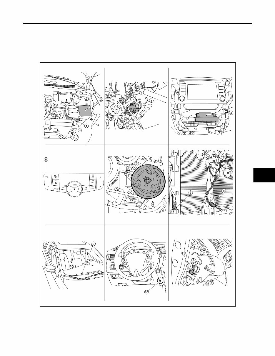
COMPONENT PARTS HAC-9 < SYSTEM DESCRIPTION > [AUTOMATIC AIR CONDITIONER] C D E F G H J K L M A B HAC N O P SYSTEM DESCRIPTION COMPONENT PARTS Component Part Location INFOID:0000000011538358 ALIIA0703ZZ Revision: December 2014 2015 Sentra NAM
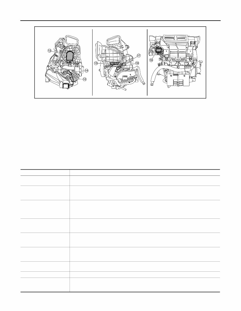
HAC-10 < SYSTEM DESCRIPTION > [AUTOMATIC AIR CONDITIONER] COMPONENT PARTS Component Description INFOID:0000000011538359 1. ECM 2. IPDM E/R 3. BCM (view with instrument panel re- moved) 4. A/C auto amp. (view with A/C switch assembly removed) 5. A/C switch assembly 6. A/C Compressor 7. Refrigerant pressure sensor (view with front bumper fascia removed) 8. Ambient sensor 9. Sunload sensor 10. In-vehicle sensor 11. Blower motor relay 12. Blower motor (view with front A/C assembly removed from vehicle) 13. Air mix door motor RH 14. Mode door motor 15. Intake door motor 16. Air mix door motor LH 17. Intake sensor 18. Variable blower control ALIIA0704ZZ Component Description A/C auto amp. A/C auto amp. controls front automatic air conditioning system by inputting and calculating signals from each sensor and each switch. A/C Compressor Vaporized refrigerant is drawn into the A/C compressor from the evaporator, where it is compressed to a high pressure, high temperature vapor. The hot, compressed vapor is then discharged to the con- denser. A/C switch assembly The A/C switch assembly controls the operation of the A/C and heating system based on inputs from the temperature control knob, the mode switches, the blower control dial, the ambient temperature sensor, the intake sensor, and inputs received from the ECM across the CAN. Diagnosis of the A/C switch assembly can be performed using the CONSULT. Air mix door motor LH The air mix door controls the mix of hot or cold air that enters the ventilation system. It is controlled by the A/C auto amp. based on the position of the temperature dial. The air mix door motor LH re- ceives position commands from the A/C auto amp. Air mix door motor RH The air mix door controls the mix of hot or cold air that enters the ventilation system. It is controlled by the A/C auto amp. based on the position of the temperature dial. The air mix door motor RH re- ceives position commands from the A/C auto amp. Ambient sensor The ambient sensor measures the temperature of the air surrounding the vehicle. The sensor uses a thermistor which is sensitive to the change in temperature. The electrical resistance of the thermistor decreases as temperature increases. BCM The BCM receives the fan ON and A/C ON signals from the A/C auto amp. and sends a compressor ON request to the ECM. Blower motor The blower motor varies the speed at which the air flows through the ventilation system. Blower motor relay The blower motor relay controls the flow of current to fuse 20, 21 and 22 in the Fuse Block (J/B). The relay is connected directly to ground, and is energized when the ignition switch is in the ON or START position. Revision: December 2014 2015 Sentra NAM
The 2014 Nissan Sentra Service & Repair Manual is the ultimate resource for DIY car maintenance. This comprehensive manual includes all the troubleshooting and replacement procedures recommended by the manufacturer, with step-by-step instructions, clear images, and exploded-view illustrations.
With the durability of your vehicle in mind, this manual also stresses the importance of regular maintenance to ensure its reliability. Even with proper upkeep, certain parts will eventually wear out and need to be replaced. That's where the 2014 Nissan Sentra Service & Repair Manual comes in handy, providing you with all the necessary information to fix your car yourself and save on costly repairs.
Gone are the days of flipping through hundreds of pages to find specific information, as this manual is easily searchable and accessible on any electronic device. No more greasy, torn, or lost pages, and the convenience of being able to carry it around, search, screenshot, and bookmark pages makes it a better alternative to traditional bound manuals. And if you prefer a physical copy, you can easily print it out.
Compatible with a wide range of devices, including PC and Mac computers, smartphones, and tablets, and requiring only the free Adobe Reader, the 2014 Nissan Sentra Service & Repair Manual is a must-have for any owner looking to maintain their vehicle in top condition. Don't wait until something goes wrong, be prepared with this comprehensive and user-friendly manual.
Models covered:
2014 Nissan Sentra S
2014 Nissan Sentra SV
2014 Nissan Sentra SR
2014 Nissan Sentra SL
Printable: Yes Language: English Compatibility: Pretty much any electronic device, incl. PC & Mac computers, Android and Apple smartphones & tablet, etc. Requirements: Adobe Reader (free)