LT-1 ELECTRICAL C D E F G H I J L M SECTION LT A B LT N O P CONTENTS LIGHTING SYSTEM SERVICE INFORMATION ........................... 3 PRECAUTIONS .................................................. 3 Precaution for Supplemental Restraint System (SRS) "AIR BAG" and "SEAT BELT PRE-TEN- SIONER" .................................................................. 3 HEADLAMP (FOR USA) .................................... 4 Component Parts and Harness Connector Loca- tion ........................................................................... 4 System Description .................................................. 4 CAN COMMUNICATION SYSTEM DESCRIP- TION ......................................................................... 5 Schematic ................................................................ 6 Wiring Diagram ........................................................ 7 Terminal and Reference Value for BCM ................ 10 Terminal and Reference Value for IPDM E/R ........ 10 How to Perform Trouble Diagnosis ........................ 11 Preliminary Check .................................................. 11 CONSULT-III Function (BCM) ................................ 11 CONSULT-III Function (IPDM E/R) ........................ 12 Headlamp High Beam Does Not Illuminate (Both Sides) ..................................................................... 13 Headlamp High Beam Does Not Illuminate (One Side) ....................................................................... 15 High Beam Indicator Lamp Does Not Illuminate .... 16 Headlamp Low Beam Does Not Illuminate (Both Sides) ..................................................................... 16 Headlamp Low Beam Does Not Illuminate (One Side) ....................................................................... 19 Headlamps Do Not Turn OFF ................................ 20 Aiming Adjustment ................................................. 21 Bulb Replacement .................................................. 22 Removal and Installation ........................................ 23 Disassembly and Assembly ................................... 24 HEADLAMP (FOR CANADA) - DAYTIME LIGHT SYSTEM - ..............................................25 Component Parts and Harness Connector Loca- tion ......................................................................... 25 System Description ................................................ 25 CAN Communication System Description ..............27 Schematic ...............................................................28 Wiring Diagram - DTRL - ........................................29 Terminal and Reference Value for BCM .................32 Terminal and Reference Value for IPDM E/R .........32 How to Perform Trouble Diagnosis .........................33 Preliminary Check ..................................................33 CONSULT-III Function (BCM) ................................33 CONSULT-III Function (IPDM E/R) ........................33 Daytime Light Control Does Not Operate Properly (High Beam Headlamps Operate Properly) ............33 Aiming Adjustment ..................................................34 Bulb Replacement ..................................................34 Removal and Installation ........................................34 Disassembly and Assembly ....................................35 FRONT FOG LAMP .......................................... 36 Component Parts and Harness Connector Loca- tion ..........................................................................36 System Description .................................................36 CAN Communication System Description ..............37 Wiring Diagram - F/FOG - ......................................38 Terminal and Reference Value for BCM .................39 Terminal and Reference Value for IPDM E/R .........39 How to Proceed with Trouble Diagnosis .................40 Preliminary Check ..................................................40 CONSULT-III Function (BCM) ................................40 CONSULT-III Function (IPDM E/R) ........................40 Front Fog lamps Do Not Illuminate (Both Sides) ....40 Front Fog Lamp Does Not Illuminate (One Side) ....42 Aiming Adjustment ..................................................43 Bulb Replacement ..................................................43 Removal and Installation, All Except SE-R .............44 Removal and Installation, SE-R ..............................44 TURN SIGNAL AND HAZARD WARNING LAMPS .............................................................. 45 Component Parts and Harness Connector Loca- tion ..........................................................................45 System Description .................................................45 CAN Communication System Description ..............47
LT-2 Schematic .............................................................. 48 Wiring Diagram - TURN - ....................................... 49 Terminal and Reference Value for BCM ................ 52 How to Proceed with Trouble Diagnosis ................ 52 Preliminary Check ................................................. 53 CONSULT-III Function (BCM) ............................... 53 Turn Signals Do Not Operate ................................ 53 Front Turn Signal Lamp Does Not Operate ........... 53 Rear Turn Signal Lamp Does Not Operate ........... 54 Hazard Warning Lamp Does Not Operate But Turn Signal Lamp Operatess ................................. 55 Turn Signal Indicator Lamp Does Not Operate ..... 56 Bulb Replacement for Front Turn Signal Lamp ..... 56 Bulb Replacement for Rear Turn Signal Lamp ...... 56 Removal and Installation of Front Turn Signal Lamp ...................................................................... 56 Removal and Installation of Rear Turn Signal Lamp ...................................................................... 56 LIGHTING AND TURN SIGNAL SWITCH ........ 57 Removal and Installation ....................................... 57 HAZARD SWITCH ............................................ 58 Removal and Installation ....................................... 58 COMBINATION SWITCH ................................. 59 Wiring Diagram - COMBSW - ................................ 59 Combination Switch Reading Function .................. 59 Terminal and Reference Value for BCM ................ 60 CONSULT-III Function (BCM) ............................... 60 Combination Switch Inspection ............................. 60 Removal and Installation ....................................... 62 STOP LAMP ..................................................... 63 Wiring Diagram - STOP/L - .................................... 63 Bulb Replacement for High-Mounted Stop Lamp ... 63 Bulb Replacement for Rear Combination Lamp for Stop Lamp ............................................................. 64 Removal and Installation of High-Mounted Stop Lamp, All Except SE-R .......................................... 64 Removal and Installation of High-Mounted Stop Lamp, SE-R ........................................................... 64 Removal and Installation of Rear Combination Lamp for Stop Lamp .............................................. 64 BACK-UP LAMP ............................................... 65 Wiring Diagram - BACK/L - .................................... 65 Bulb Replacement ................................................. 65 Removal and Installation ....................................... 66 PARKING, LICENSE PLATE AND TAIL LAMPS .............................................................. 67 Component Parts and Harness Connector Loca- tion ......................................................................... 67 System Description ................................................ 67 CAN Communication System Description ............. 68 Schematic .............................................................. 69 Wiring Diagram - TAIL/L - ...................................... 70 Terminal and Reference Value for BCM ................ 72 Terminal and Reference Value for IPDM E/R ........ 72 How to Proceed with Trouble Diagnosis ................ 73 Preliminary Check .................................................. 73 CONSULT-III Function (BCM) ............................... 73 CONSULT-III Function (IPDM E/R) ....................... 73 Parking, License Plate and Tail Lamps Do Not Il- luminate ................................................................. 73 Front Parking Lamps Do Not Illuminate (License Plate and Tail Lamps Operate Normally) ............... 74 License Plate and Tail Lamps Do Not Illuminate (Front Parking Lamps Operate Normally) .............. 75 Parking, License Plate and Tail Lamps Do Not Turn OFF (After Approx. 10 Minutes) .................... 77 Bulb Replacement .................................................. 77 Removal and Installation ........................................ 77 REAR COMBINATION LAMP .......................... 79 Component ............................................................ 79 Bulb Replacement .................................................. 79 Removal and Installation ........................................ 80 Disassembly and Assembly ................................... 80 INTERIOR LAMP .............................................. 81 Map Lamp .............................................................. 81 Trunk Room Lamp ................................................. 81 INTERIOR ROOM LAMP .................................. 83 Component Parts and Harness Connector Loca- tion ......................................................................... 83 System Description ................................................ 83 Schematic .............................................................. 87 Wiring Diagram - INT/L - ........................................ 88 Terminal and Reference Value for BCM ................ 91 How to Proceed with Trouble Diagnosis ................ 91 Preliminary Check .................................................. 92 CONSULT-III Function (BCM) ............................... 92 Interior Room Lamp Control Does Not Operate ..... 93 Bulb Replacement .................................................. 94 Removal and Installation ........................................ 94 ILLUMINATION ................................................ 96 System Description ................................................ 96 CAN Communication System Description ............. 97 Schematic .............................................................. 98 Wiring Diagram - ILL - ............................................ 99 Bulb Replacement ................................................ 104 Removal and Installation ...................................... 105 BULB SPECIFICATIONS ................................ 106 Headlamp ............................................................. 106 Exterior Lamp ....................................................... 106 Interior Lamp/Illumination ..................................... 106
PRECAUTIONS LT-3 < SERVICE INFORMATION > C D E F G H I J L M A B LT N O P SERVICE INFORMATION PRECAUTIONS Precaution for Supplemental Restraint System (SRS) "AIR BAG" and "SEAT BELT PRE-TENSIONER" INFOID:0000000004409087 The Supplemental Restraint System such as “AIR BAG” and “SEAT BELT PRE-TENSIONER”, used along with a front seat belt, helps to reduce the risk or severity of injury to the driver and front passenger for certain types of collision. This system includes seat belt switch inputs and dual stage front air bag modules. The SRS system uses the seat belt switches to determine the front air bag deployment, and may only deploy one front air bag, depending on the severity of a collision and whether the front occupants are belted or unbelted. Information necessary to service the system safely is included in the SRS and SB section of this Service Man- ual. WARNING: • To avoid rendering the SRS inoperative, which could increase the risk of personal injury or death in the event of a collision which would result in air bag inflation, all maintenance must be performed by an authorized NISSAN/INFINITI dealer. • Improper maintenance, including incorrect removal and installation of the SRS, can lead to personal injury caused by unintentional activation of the system. For removal of Spiral Cable and Air Bag Module, see the SRS section. • Do not use electrical test equipment on any circuit related to the SRS unless instructed to in this Service Manual. SRS wiring harnesses can be identified by yellow and/or orange harnesses or har- ness connectors.
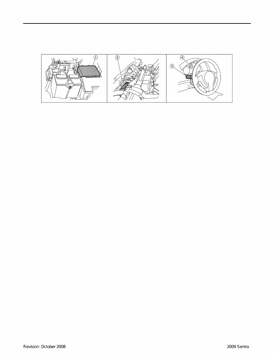
LT-4 < SERVICE INFORMATION > HEADLAMP (FOR USA) HEADLAMP (FOR USA) Component Parts and Harness Connector Location INFOID:0000000004409088 System Description INFOID:0000000004409089 Headlamp operation is controlled by the BCM (body control module) based on inputs from the combination switch (lighting switch). When the lighting switch is placed in the 2ND position, the BCM receives an input sig- nal requesting the headlamps (and tail lamps) illuminate. The BCM sends a signal, via the CAN communica- tion lines, to the IPDM E/R (intelligent power distribution module engine room) requesting the headlamps be turned ON. The CPU (central processing unit) located in the IPDM E/R controls ground for the headlamp high and headlamp low relay coils. These relays direct power to the respective headlamps, which then illuminate. OUTLINE Power is supplied at all times • to headlamp high relay RH and LH (located in IPDM E/R), • to headlamp low relay (located in IPDM E/R), • to ignition relay (located in IPDM E/R), • through 15A fuse (No. 52, located in IPDM E/R) and • through 20A fuse (No. 53, located in IPDM E/R) • to CPU located in IPDM E/R, • through 50A fusible link (letter j, located in fuse and fusible link block) • to BCM terminal 70, • through 10A fuse [No. 21, located in fuse block (J/B)] • to BCM terminal 57, and • through 10A fuse [No. 19, located in fuse block (J/B)] • to combination meter terminal 1. With the ignition switch in the ON or START position, power is supplied • to the ignition relay (located in IPDM E/R), • through 10A fuse [No. 12, located in fuse block (J/B)] • to BCM terminal 38, • through 10A fuse [No. 14, located in fuse block (J/B)] • to combination meter terminal 2. With the ignition switch in the ACC or ON position, power is supplied • through 10A fuse [No. 6, located in fuse block (J/B)] • to BCM terminal 11. Ground is supplied • to BCM terminal 67 • to combination meter terminals 3 and 21 • through grounds M57 and M61, and • to IPDM E/R terminals 39 and 59 • through grounds E9, E15 (all models) and E24 (with MR20DE). HEADLAMP OPERATION Low Beam Operation 1. IPDM E/R E46, E47 and E48 2. BCM M18 and M20 (view with instru- ment panel removed) 3. Combination switch (lighting switch) M28 4. Combination meter M24 WKIA5751E
HEADLAMP (FOR USA) LT-5 < SERVICE INFORMATION > C D E F G H I J L M A B LT N O P With the lighting switch in 2ND position, the BCM receives an input signal requesting the headlamps to illumi- nate. The BCM then sends a signal, via the CAN communication lines, to the IPDM E/R requesting the low beam headlamps be turned ON. The CPU located in the IPDM E/R controls ground to the headlamp low relay coil, which when energized, directs power • through 15A fuse (No. 41, located in IPDM E/R) • through IPDM E/R terminal 54 • to headlamp RH terminal 3, and • through 15A fuse (No. 40, located in IPDM E/R) • through IPDM E/R terminal 52 • to headlamp LH terminal 3. Ground is supplied • to headlamp RH and LH terminals 5 • through grounds E9, E15 (all models) and E24 (with MR20DE). With power and ground supplied, low beam headlamps illuminate. High Beam Operation/Flash-to-Pass Operation With the lighting switch in 2ND position and high beam switch in the HIGH position, the BCM receives an input signal requesting the headlamp high beams to illuminate. The flash to pass feature can be used any time and also sends a signal to the BCM. This input signal is then communicated to the IPDM E/R and the combination meter via the CAN communication lines. The CPU located in the IPDM E/R controls the headlamp high relays (LH and RH), which when energized, directs power • through 10A fuse (No. 34, located in IPDM E/R) • through IPDM E/R terminal 56 • to headlamp RH terminal 6, and • through 10A fuse (No. 35, located in IPDM E/R) • through IPDM E/R terminal 55 • to headlamp LH terminal 6. Ground is supplied • to headlamp RH and LH terminal 5 • through grounds E9, E15 (all models) and E24 (with MR20DE). With power and ground supplied, the high beam headlamps illuminate. The BCM sends a signal, via the CAN communication lines, to the combination meter requesting the high beam indicator lamp be turned ON. COMBINATION SWITCH READING FUNCTION Refer to LT-59, "Combination Switch Reading Function" . CAN COMMUNICATION SYSTEM DESCRIPTION INFOID:0000000004409090 Refer to LAN-6, "System Description" .
You're Reading a Preview
What's Included?
Lifetime Access
Fast Download Speeds
Offline Viewing
Access Contents & Bookmarks
Full Search Facility
Print one or all pages of your manual
$36.99
2009 Nissan Sentra Service & Repair Manual Software
Keep your 2009 Nissan Sentra in top condition with this comprehensive Service & Repair Manual. Tailored for the 2009 Nissan Sentra, this manual offers detailed instructions and diagrams for various maintenance and repair tasks.
Whether you're a professional mechanic or a DIY enthusiast, this manual is your go-to resource for part replacements, issue troubleshooting, and routine maintenance. It covers all vehicle aspects, including the engine, transmission, brakes, and electrical system.
By using this manual, you can save time and money by handling repairs yourself, eliminating the need for a mechanic or extensive online research. All the necessary information is easily accessible.
Key Features:
Step-by-step instructions
Clear diagrams and illustrations
Diagnostic trouble codes
Wiring diagrams
Component locations
Maintenance schedules
Models Included:
2009 Nissan Sentra Base Model
2009 Nissan Sentra S
2009 Nissan Sentra SL
Don't let car issues hinder your driving experience. Take charge of your 2009 Nissan Sentra's maintenance and repairs with this convenient and comprehensive Service & Repair Manual.
Reviews
Q&A
Recently Viewed
5,521,897Happy Clients
2,594,462eManuals
1,120,453Trusted Sellers
15Years in Business
Price:
Actual Price:
2009 Nissan Sentra Service & Repair Manual Software






 Lifetime Access




