


ACC-1
ENGINE
C
D
E
F
G
H
I
J
K
L
M
SECTION ACC
A
ACC
N
O
P
CONTENTS
ACCELERATOR CONTROL SYSTEM
PRECAUTION .............................................. 2
PRECAUTIONS .................................................. 2
FOR USA AND CANADA ........................................... 2
FOR USA AND CANADA : Precaution for Supple-
mental Restraint System (SRS) "AIR BAG" and
"SEAT BELT PRE-TENSIONER" ............................. 2
FOR MEXICO ............................................................. 2
FOR MEXICO : Precaution for Supplemental Re-
straint System (SRS) "AIR BAG" and "SEAT BELT
PRE-TENSIONER" .................................................. 2
REMOVAL AND INSTALLATION ............... 4
ACCELERATOR CONTROL SYSTEM .............. 4
Exploded View ......................................................... 4
Removal and Installation ......................................... 4
Inspection ................................................................ 5
Revision: 2013 February 2012 ROGUE

ACC-2
< PRECAUTION >
PRECAUTIONS
PRECAUTION
PRECAUTIONS
FOR USA AND CANADA
FOR USA AND CANADA : Precaution for Supplemental Restraint System (SRS) "AIR
BAG" and "SEAT BELT PRE-TENSIONER" INFOID:0000000007737507
The Supplemental Restraint System such as “AIR BAG” and “SEAT BELT PRE-TENSIONER”, used along
with a front seat belt, helps to reduce the risk or severity of injury to the driver and front passenger for certain
types of collision. This system includes seat belt switch inputs and dual stage front air bag modules. The SRS
system uses the seat belt switches to determine the front air bag deployment, and may only deploy one front
air bag, depending on the severity of a collision and whether the front occupants are belted or unbelted.
Information necessary to service the system safely is included in the “SRS AIR BAG” and “SEAT BELT” of this
Service Manual.
WARNING:
Always observe the following items for preventing accidental activation.
• To avoid rendering the SRS inoperative, which could increase the risk of personal injury or death in
the event of a collision that would result in air bag inflation, all maintenance must be performed by
an authorized NISSAN/INFINITI dealer.
• Improper maintenance, including incorrect removal and installation of the SRS, can lead to personal
injury caused by unintentional activation of the system. For removal of Spiral Cable and Air Bag
Module, see “SRS AIR BAG”.
• Never use electrical test equipment on any circuit related to the SRS unless instructed to in this Ser-
vice Manual. SRS wiring harnesses can be identified by yellow and/or orange harnesses or harness
connectors.
PRECAUTIONS WHEN USING POWER TOOLS (AIR OR ELECTRIC) AND HAMMERS
WARNING:
Always observe the following items for preventing accidental activation.
• When working near the Air Bag Diagnosis Sensor Unit or other Air Bag System sensors with the
ignition ON or engine running, never use air or electric power tools or strike near the sensor(s) with
a hammer. Heavy vibration could activate the sensor(s) and deploy the air bag(s), possibly causing
serious injury.
• When using air or electric power tools or hammers, always switch the ignition OFF, disconnect the
battery, and wait at least 3 minutes before performing any service.
FOR MEXICO
FOR MEXICO : Precaution for Supplemental Restraint System (SRS) "AIR BAG" and
"SEAT BELT PRE-TENSIONER" INFOID:0000000007737570
The Supplemental Restraint System such as “AIR BAG” and “SEAT BELT PRE-TENSIONER”, used along
with a front seat belt, helps to reduce the risk or severity of injury to the driver and front passenger for certain
types of collision. Information necessary to service the system safely is included in the “SRS AIR BAG” and
“SEAT BELT” of this Service Manual.
WARNING:
Always observe the following items for preventing accidental activation.
• To avoid rendering the SRS inoperative, which could increase the risk of personal injury or death in
the event of a collision that would result in air bag inflation, all maintenance must be performed by
an authorized NISSAN/INFINITI dealer.
• Improper maintenance, including incorrect removal and installation of the SRS, can lead to personal
injury caused by unintentional activation of the system. For removal of Spiral Cable and Air Bag
Module, see “SRS AIR BAG”.
• Never use electrical test equipment on any circuit related to the SRS unless instructed to in this Ser-
vice Manual. SRS wiring harnesses can be identified by yellow and/or orange harnesses or harness
connectors.
PRECAUTIONS WHEN USING POWER TOOLS (AIR OR ELECTRIC) AND HAMMERS
WARNING:
Revision: 2013 February 2012 ROGUE

PRECAUTIONS
ACC-3
< PRECAUTION >
C
D
E
F
G
H
I
J
K
L
M
A
ACC
N
P
O
Always observe the following items for preventing accidental activation.
• When working near the Air Bag Diagnosis Sensor Unit or other Air Bag System sensors with the
ignition ON or engine running, never use air or electric power tools or strike near the sensor(s) with
a hammer. Heavy vibration could activate the sensor(s) and deploy the air bag(s), possibly causing
serious injury.
• When using air or electric power tools or hammers, always switch the ignition OFF, disconnect the
battery, and wait at least 3 minutes before performing any service.
Revision: 2013 February 2012 ROGUE
ACC-4
< REMOVAL AND INSTALLATION >
ACCELERATOR CONTROL SYSTEM
REMOVAL AND INSTALLATION
ACCELERATOR CONTROL SYSTEM
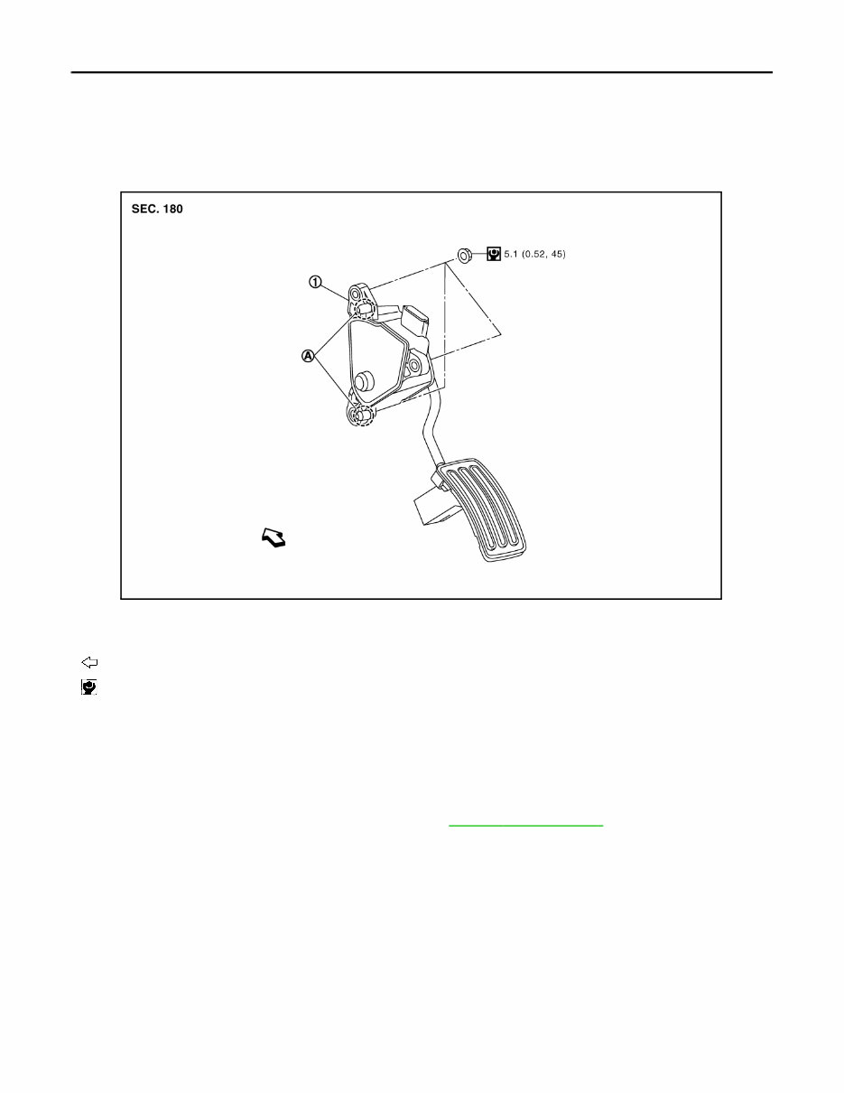
Exploded View INFOID:0000000007351136
Removal and Installation INFOID:0000000007351137
REMOVAL
1. Disconnect accelerator pedal position sensor harness connector.
2. Remove accelerator pedal assembly mounting nuts.
3. Loosen brake pedal assembly mounting nuts. Refer to BR-19, " Exploded View " .
NOTE:
Brake pedal assembly does not have to be removed from the vehicle.
4. Remove accelerator pedal assembly.
CAUTION:
• Never disassemble accelerator lever. Never remove accelerator pedal position sensor from
accelerator lever.
• Avoid impact from dropping etc. during handling.
• Be careful to keep accelerator lever away from water.
INSTALLATION
Note the following, and install in the reverse order of removal.
• Insert locating pin into vehicle side to position accelerator pedal assembly. Tighten mounting nuts to acceler-
ator pedal assembly.
1. Accelerator pedal assembly
A. Locating pin
: Vehicle front
: N·m (kg-m, in-lb)
JPBIA1270GB
Revision: 2013 February 2012 ROGUE

ACCELERATOR CONTROL SYSTEM
ACC-5
< REMOVAL AND INSTALLATION >
C
D
E
F
G
H
I
J
K
L
M
A
ACC
N
P
O
Inspection INFOID:0000000007351138
INSPECTION AFTER INSTALLATION
• Check that accelerator pedal moves smoothly within the whole operation range when it is depressed fully
and released.
• Check that accelerator pedal returns securely to the fully released position.
• For the electrical inspection of accelerator pedal position sensor. Refer to the following:
- For Mexico: EC-718, " Component Inspection " .
- Except for Mexico: EC-374, " Component Inspection " .
- CAUTION:
When harness connector of accelerator pedal position sensor is disconnected, perform “ACCELEA-
TOR PEDAL RELEASED POSITION LEARNING”. Refer to EC-473, " ACCELERATOR PEDAL
RELEASED POSITION LEARNING : Description " (for Mexico) or EC-23, " ACCELERATOR PEDAL
RELEASED POSITION LEARNING : Description " (Except for Mexico).
Revision: 2013 February 2012 ROGUE
You're Reading a Preview
What's Included?
 Lifetime Access
Fast Download Speeds
Offline Viewing
Access Contents & Bookmarks
Full Search Facility
Print one or all pages of your manual
$36.99
2012 Nissan Rogue Service & Repair Manual
Viewed 19 Times Today

What's Included?
Lifetime Access
Fast Download Speeds
Offline Viewing
Access Contents & Bookmarks
Full Search Facility
Print one or all pages of your manual
$36.99

Secure transaction
What's Included?
Lifetime Access
Fast Download Speeds
Offline Viewing
Access Contents & Bookmarks
Full Search Facility
Print one or all pages of your manual
Description
The 2012 Nissan Rogue Service & Repair Manual is a comprehensive guide tailored to assist owners and mechanics in maintaining and repairing their Nissan Rogue vehicles. It offers detailed instructions and diagrams for various service and repair procedures.
Key features of this manual include:
- Step-by-step instructions for common maintenance tasks such as oil changes, tire rotations, and brake repairs
- Detailed explanations and diagrams for diagnosing and troubleshooting various engine, electrical, and mechanical issues
- Comprehensive information on the vehicle's systems, including the engine, transmission, suspension, and electrical components
- Specifications and procedures for adjusting and repairing the vehicle's various components
- Special tools and equipment required for certain procedures
Whether you're a professional mechanic or an enthusiastic do-it-yourselfer, the 2012 Nissan Rogue Service & Repair Manual provides all the necessary information and guidance to keep your Nissan Rogue running smoothly. With clear instructions and detailed diagrams, this manual is an invaluable resource for anyone looking to maintain or repair their Nissan Rogue.


