HAC-1 VENTILATION, HEATER & AIR CONDITIONER C D E F G H J K L M SECTION HAC A B HAC N O P CONTENTS HEATER & AIR CONDITIONING CONTROL SYSTEM MANUAL AIR CONDITIONER BASIC INSPECTION ................................... 3 DIAGNOSIS AND REPAIR WORKFLOW ......... 3 Work Flow ................................................................ 3 INSPECTION AND ADJUSTMENT .................... 4 Description & Inspection .......................................... 4 SYSTEM DESCRIPTION ............................. 5 COMPRESSOR CONTROL FUNCTION ............ 5 Description ............................................................... 5 Component Part Location ........................................ 6 Component Description ............................................ 7 MANUAL AIR CONDITIONER SYSTEM ........... 9 System Diagram ....................................................... 9 System Description .................................................. 9 Component Part Location ...................................... 15 Component Description .......................................... 17 DIAGNOSIS SYSTEM (BCM) ...........................19 COMMON ITEM ........................................................ 19 COMMON ITEM : CONSULT-III Function (BCM - COMMON ITEM) .................................................... 19 AIR CONDITIONER .................................................. 19 AIR CONDITIONER : CONSULT-III Function ........ 20 MAGNET CLUTCH CONTROL SYSTEM .........21 System Diagram ..................................................... 21 System Description ................................................ 21 DTC/CIRCUIT DIAGNOSIS ........................ 22 MODE DOOR MOTOR ......................................22 Description ............................................................. 22 Component Function Check ................................. 22 Diagnosis Procedure .............................................. 22 AIR MIX DOOR MOTOR ................................... 24 Description ..............................................................24 Component Function Check .................................24 Diagnosis Procedure ..............................................24 INTAKE DOOR MOTOR ................................... 26 Description ..............................................................26 Component Function Check .................................26 Diagnosis Procedure ..............................................26 BLOWER MOTOR ............................................ 28 Description ..............................................................28 Component Function Check .................................28 Diagnosis Procedure ..............................................28 Component Inspection (Blower Motor) ...................31 Component Inspection (Fan Control Amp.) ............31 MAGNET CLUTCH ........................................... 32 Description ..............................................................32 Component Function Check ...................................32 Diagnosis Procedure ..............................................32 INTAKE SENSOR ............................................. 36 Description ..............................................................36 Diagnosis Procedure ..............................................36 Component Inspection ............................................37 POWER SUPPLY AND GROUND CIRCUIT FOR A/C AMP. .................................................. 38 Description ..............................................................38 Component Function Check ...................................38 Diagnosis Procedure ..............................................38 ECU DIAGNOSIS INFORMATION ............. 40 BCM (BODY CONTROL MODULE) ................. 40 Reference Value .....................................................40 A/C AMP. ........................................................... 55 Reference Value .....................................................55 Wiring Diagram — AIR CONDITIONER CON- TROL SYSTEM — ..................................................57 Revision: 2009 October 2010 Rogue
HAC-2 SYMPTOM DIAGNOSIS ............................ 63 MANUAL AIR CONDITIONER SYSTEM .......... 63 Diagnosis Chart By Symptom ................................ 63 INSUFFICIENT COOLING ................................ 64 Description ............................................................. 64 Inspection procedure ............................................. 64 INSUFFICIENT HEATING ................................ 65 Description ............................................................. 65 Inspection procedure ............................................. 65 NOISE ............................................................... 67 Description ............................................................. 67 Inspection procedure ............................................. 67 PRECAUTION ............................................ 69 PRECAUTIONS ................................................ 69 FOR USA AND CANADA ........................................ 69 FOR USA AND CANADA : Precaution for Supple- mental Restraint System (SRS) "AIR BAG" and "SEAT BELT PRE-TENSIONER" .......................... 69 FOR USA AND CANADA : Precaution Necessary for Steering Wheel Rotation After Battery Discon- nect ........................................................................ 69 FOR USA AND CANADA : Precaution for Proce- dure without Cowl Top Cover ................................ 70 FOR USA AND CANADA : Precautions For Xenon Headlamp Service ................................................. 70 FOR USA AND CANADA : Working with HFC- 134a (R-134a) ....................................................... 70 FOR USA AND CANADA : General Refrigerant Precaution ............................................................. 71 FOR USA AND CANADA : Refrigerant Connec- tion ......................................................................... 71 FOR USA AND CANADA : Service Equipment ..... 73 FOR MEXICO ........................................................... 75 FOR MEXICO : Precaution for Supplemental Re- straint System (SRS) "AIR BAG" and "SEAT BELT PRE-TENSIONER" ................................................ 75 FOR MEXICO : Precaution Necessary for Steer- ing Wheel Rotation After Battery Disconnect ........ 75 FOR MEXICO : Precaution for Procedure without Cowl Top Cover ..................................................... 76 FOR MEXICO : Precautions For Xenon Headlamp Service ................................................................... 76 FOR MEXICO : Working with HFC-134a (R-134a) ... 77 FOR MEXICO : General Refrigerant Precaution ... 77 FOR MEXICO : Refrigerant Connection ................ 78 FOR MEXICO : Service Equipment ....................... 80 COMPRESSOR ................................................ 82 General Precautions .............................................. 82 FLUORESCENT LEAK DETECTOR ................ 83 General Precautions .............................................. 83 PREPARATION .......................................... 84 PREPARATION ................................................ 84 Special Service Tool .............................................. 84 Commercial Service Tool ....................................... 86 Sealant or/and Lubricant ........................................ 86 REMOVAL AND INSTALLATION .............. 88 A/C CONTROL ................................................. 88 Exploded View ....................................................... 88 Removal and Installation ........................................ 88 INTAKE SENSOR ............................................. 89 Exploded View ....................................................... 89 Removal and Installation ........................................ 89 REFRIGERANT PRESSURE SENSOR ........... 90 Exploded View ....................................................... 90 Removal and Installation ........................................ 90 DOOR MOTOR ................................................. 91 Exploded View ....................................................... 91 INTAKE DOOR MOTOR .......................................... 91 INTAKE DOOR MOTOR : Removal and Installa- tion ......................................................................... 91 MODE DOOR MOTOR ............................................. 91 MODE DOOR MOTOR : Removal and Installation ... 91 AIR MIX DOOR MOTOR .......................................... 91 AIR MIX DOOR MOTOR : Removal and Installa- tion ......................................................................... 92 Revision: 2009 October 2010 Rogue
DIAGNOSIS AND REPAIR WORKFLOW HAC-3 < BASIC INSPECTION > [MANUAL AIR CONDITIONER] C D E F G H J K L M A B HAC N O P BASIC INSPECTION DIAGNOSIS AND REPAIR WORKFLOW Work Flow INFOID:0000000005254357 DETAILED FLOW 1.LISTEN TO CUSTOMER COMPLAINT Listen to customer complaint. (Get detailed information about the conditions and environment when the symp- tom occurs.) >> GO TO 2. 2.VERIFY THE SYMPTOM WITH OPERATIONAL CHECK Verify the symptom with operational check. Refer to HAC-4, " Description & Inspection " . >> GO TO 3. 3.GO TO APPROPRIATE TROUBLE DIAGNOSIS Go to appropriate trouble diagnosis (Refer to HAC-63, " Diagnosis Chart By Symptom " below). >> GO TO 4. 4.REPAIR OR REPLACE Repair or replace the specific parts. >> GO TO 5. 5.FINAL CHECK Final check. Is the inspection result normal? YES >> INSPECTION END NO >> GO TO 3. Revision: 2009 October 2010 Rogue
HAC-4 < BASIC INSPECTION > [MANUAL AIR CONDITIONER] INSPECTION AND ADJUSTMENT INSPECTION AND ADJUSTMENT Description & Inspection INFOID:0000000005254358 DESCRIPTION The purpose of the operational check is to check that the individual system operates normally. INSPECTION PROCEDURE 1.CHECKING BLOWER MOTOR 1. Turn fan control dial to 1st speed. Blower should operate on low speed. 2. Turn fan control dial to 2nd speed, and continue checking blower speed until all speeds are checked. 3. Leave blower on maximum speed. Is the inspection result normal? YES >> GO TO 2. NO >> Go to diagnosis procedure. Refer to HAC-28, " Diagnosis Procedure " . 2.CHECKING DISCHARGE AIR 1. Turn mode control dial to each position. 2. Confirm that discharge air comes out according to the air distribution table. Refer to HAC-9, " System Description " . Is the inspection result normal? YES >> GO TO 3. NO >> Go to diagnosis procedure. Refer to HAC-22, " Diagnosis Procedure " . 3.CHECKING INTAKE AIR 1. Press REC switch. Recirculation indicator lamp turns ON. 2. Press REC switch again. Recirculation indicator lamp turns OFF. 3. Listen for intake door position change. (Slight change of blower sound can be heard.) Is the inspection result normal? YES >> GO TO 4. NO >> Go to diagnosis procedure. Refer to HAC-26, " Diagnosis Procedure " . 4.CHECKING A/C SWITCH 1. Turn fan control dial to 1st speed. 2. Press A/C switch. A/C switch indicator lamp turns ON. 3. Confirm that the magnet clutch engages (sound or visual inspection). Is the inspection result normal? YES >> GO TO 5. NO >> Go to diagnosis procedure. Refer to HAC-32, " Diagnosis Procedure " . 5.CHECKING TEMPERATURE DECREASE 1. Turn temperature control dial counterclockwise until full cold position. 2. Check for cool air at discharge air outlets. Is the inspection result normal? YES >> GO TO 6. NO >> Go to diagnosis procedure. Refer to HAC-64, " Inspection procedure " . 6.CHECKING TEMPERATURE INCREASE 1. Turn temperature control dial clockwise until full hot position. 2. Check for warm air at discharge air outlets. Is the inspection result normal? YES >> INSPECTION END NO >> Go to diagnosis procedure. Refer to HAC-65, " Inspection procedure " . Conditions : Engine running at normal operating temperature Revision: 2009 October 2010 Rogue
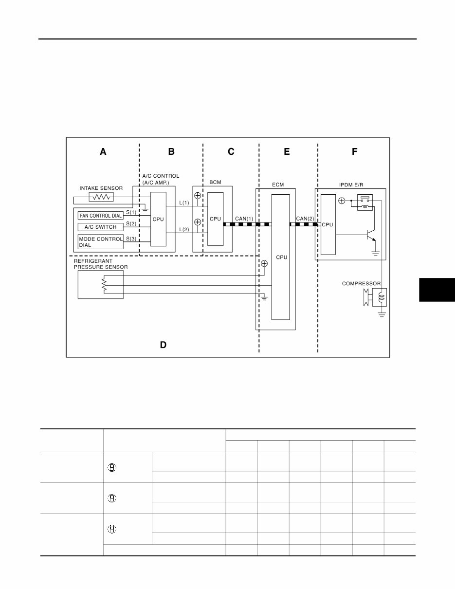
COMPRESSOR CONTROL FUNCTION HAC-5 < SYSTEM DESCRIPTION > [MANUAL AIR CONDITIONER] C D E F G H J K L M A B HAC N O P SYSTEM DESCRIPTION COMPRESSOR CONTROL FUNCTION Description INFOID:0000000005254359 PRINCIPLE OF OPERATION Compressor is not activated. Functional circuit diagram Functional Initial Inspection Chart ×: Applicable L (1) : Fan ON signal S (3) : Defogger signal L (2) : A/C switch signal CAN (1) : A/C switch signal S (1) : Fan ON signal : Blower fan motor switch signal S (2) : A/C switch signal CAN (2) : A/C compressor request signal JPIIA0394GB Control unit Diagnosis Item Location A B C D E F ECM “ENGINE” Self-diagnosis (CAN system diagnosis) – – – – × – Data monitor – – – × × – BCM “BCM” Self-diagnosis (CAN system diagnosis) – – × – – – Data monitor – × × – – – IPDM E/R “IPDM E/R” Self-diagnosis (CAN system diagnosis) – – – – – × Data monitor – – – – × – Auto active test – – – – – × Revision: 2009 October 2010 Rogue
The 2010 Nissan Rogue Service & Repair Manual is a comprehensive guide for maintaining and repairing your Nissan Rogue. Whether you are a professional mechanic or a DIY enthusiast, this manual provides the necessary information and step-by-step instructions to keep your vehicle in optimal condition.
This manual is compatible with various Nissan Rogue models, including:
2010 Nissan Rogue S
2010 Nissan Rogue SV
2010 Nissan Rogue SL
With this service and repair manual, you can save time and money by performing routine maintenance tasks and resolving common issues on your own. The clear and concise instructions, along with detailed diagrams and illustrations, make it easy to understand and follow the procedures. You will find everything you need to know about servicing and repairing your Nissan Rogue in this manual.
Whether you need to change the oil, replace the brakes, or troubleshoot electrical problems, this manual provides you with the knowledge and guidance to tackle any repair task. It covers various areas, including engine, transmission, suspension, electrical system, and more.
Invest in the 2010 Nissan Rogue Service & Repair Manual today and empower yourself with the knowledge and confidence to keep your Nissan Rogue running smoothly for years to come.






 Lifetime Access




