Precaution for Supplemental Restraint System (SRS) "AIR BAG" and "SEAT BELT PRE-TENSIONER" NISD0000000014906745 The Supplemental Restraint System such as “AIR BAG” and “SEAT BELT PRE-TENSIONER”, used along with a front seat belt, helps to reduce the risk or severity of injury to the driver and front passenger for certain types of collisions. Information necessary to service the system safely is included in the “SRS AIR BAG” and “SEAT BELT” sections of this Service Manual. WARNING: Always observe the following items for preventing accidental activation: To avoid rendering the SRS inoperative, which could increase the risk of personal injury or death in the event of a collision that would result in air bag inflation, it is recommended that all maintenance and repair be performed by an authorized NISSAN/INFINITI dealer. Improper repair, including incorrect removal and installation of the SRS, can lead to personal injury caused by unintentional activation of the system. For removal of Spiral Cable and Air Bag Module, see “SRS AIR BAG”. Never use electrical test equipment on any circuit related to the SRS unless instructed to in this Service Manual. SRS wiring harnesses can be identified by yellow and/or orange harnesses or harness connectors. PRECAUTIONS WHEN USING POWER TOOLS (AIR OR ELECTRIC) AND HAMMERS WARNING: Always observe the following items for preventing accidental activation: When working near the Air Bag Diagnosis Sensor Unit or other Air Bag System sensors with the ignition/power switch ON or engine running, never use air or electric power tools or strike near the sensor(s) with a hammer. Heavy vibration could activate the sensor(s) and deploy the air bag(s), possibly causing serious injury. When using air or electric power tools or hammers, always switch the ignition/power switch OFF, disconnect the 12V battery or batteries, and wait at least 3 minutes before performing any service.
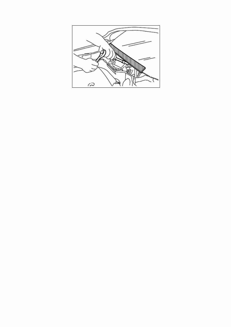
Precaution for Procedure without Cowl Top Cover When performing the procedure after removing cowl top cover, cover the lower end of windshield with urethane, etc. to prevent damage to windshield. NISD0000000014900121-01-PIIB3706J
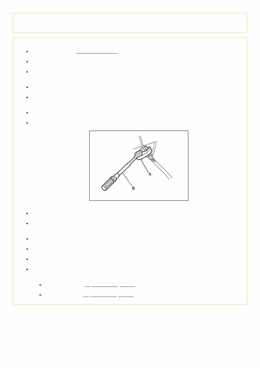
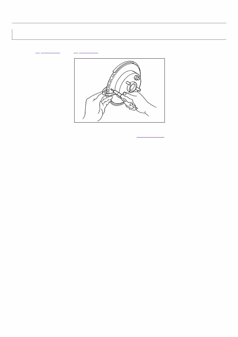
Precaution for Brake System WARNING: Clean any dust from the front brake and rear brake with a vacuum dust collector. Do not blow with compressed air. CAUTION: Brake fluid use refer to Fluids and Lubricants. Do not reuse drained brake fluid. Do not spill or splash brake fluid on painted surfaces. Brake fluid may seriously damage paint. Wipe it off immediately and wash with water if it gets on a painted surface. Always clean with new brake fluid when cleaning the master cylinder, brake caliper and other components. Do not use mineral oils such as gasoline or light oil to clean. They may damage rubber parts and cause improper operation. Always loosen the brake tube flare nut with a flare nut wrench. Tighten the brake tube flare nut to the specified torque using a crowfoot (A) and a torque wrench (B). NISD0000000014900122-01-JPFIA0001ZZ Always confirm the specified tightening torque when installing the brake pipes. Turn the ignition switch OFF and disconnect the ABS actuator and electric unit (control unit) connector or the battery negative terminal before performing the work. Always connect the battery terminal when moving the vehicle. Check that no brake fluid leakage is present after replacing the parts. Check for bends, cracks and damage to the brake pedal. Adjust brake pedal if it is outside the standard value. Burnish the brake contact surfaces after refinishing or replacing rotors, after replacing pads, or if a soft pedal occurs at very low mileage. Front brake: refer to Inspection and Adjustment. Rear brake: refer to Inspection and Adjustment.
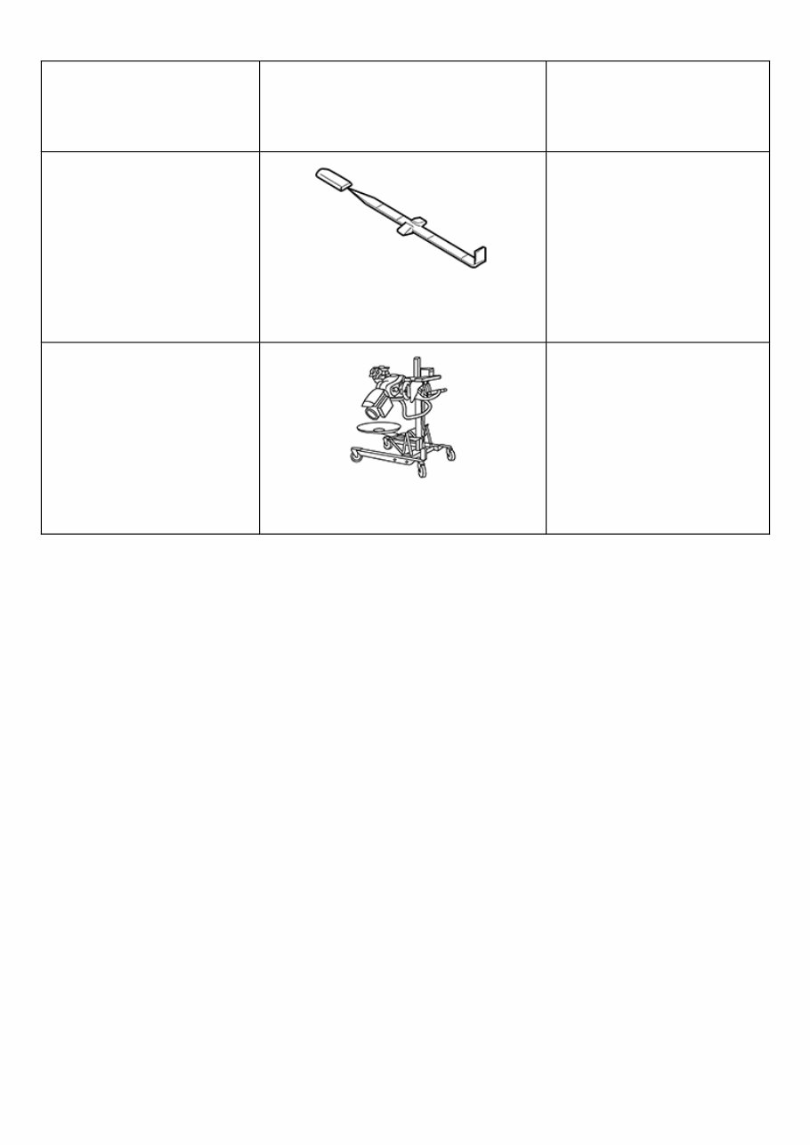
Special Service Tool NISD0000000014900123 The actual shape of the tools may differ from those illustrated here. Tool number (TechMate No.) Tool name Description — (J-46532) Brake height tool NISD0000000014900123-01- FIA0227E Measuring brake pedal height 38-PFM92 ( — ) Pro-Cut™ PFM Series Lathe NISD0000000014900123-02- WFIA1169ZZ Refinishing rotors
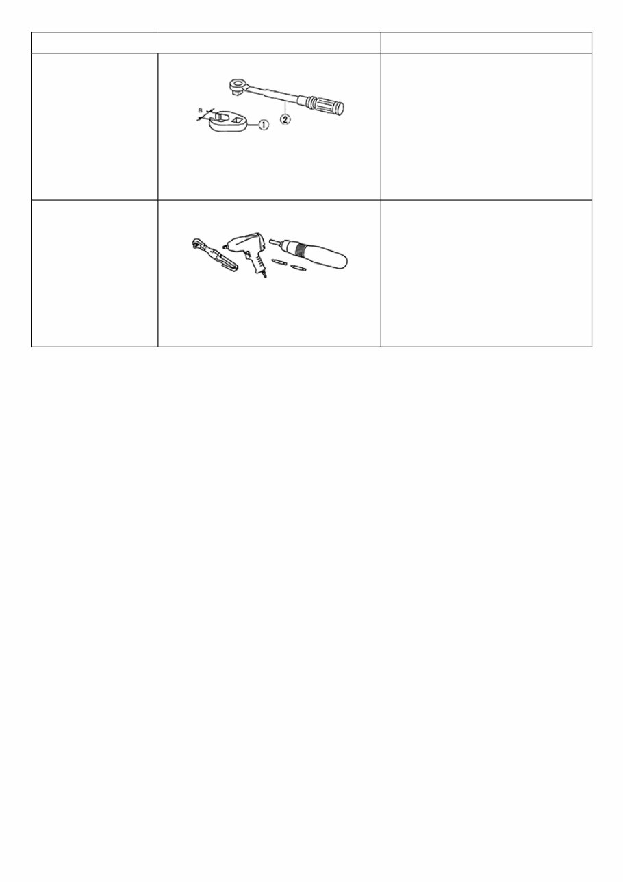
Commercial Service Tool Tool name Description 1. Flare nut crowfoot 2. Torque wrench NISD0000000014900124-01-S- NT360 Tightening brake tube flare nuts a: 10 mm (0.39 in)/12 mm (0.47 in) Power tool NISD0000000014900124-02- PIIB1407E Loosening nuts, screws and bolts
Wiring Diagram NISD0000000015244140 Refer to Wiring Diagram.
Inspection INSPECTION Uneven wear Check for uneven wear of the disc brake rotor using a micrometer. Replace the disc brake rotor if the thickness is below the wear limit. Refer to Exploded View (FWD) Exploded View (AWD). NISD0000000014900129-01-SBR020B Thickness variation (measured at 8 positions) : Refer to Rear Disc Brake.
Inspection INSPECTION Uneven Wear Check for uneven wear of the disc brake rotor using a micrometer. Replace the disc brake rotor if the thickness is below the wear limit. Refer to Exploded View (FWD) Exploded View (AWD). NISD0000000014900128-01-SBR020B Thickness variation (measured at 8 positions) : Refer to Front Disc Brake.
Inspection Check for brake fluid leakage from the following areas: Master cylinder mounting face Reservoir tank mounting face Brake tube and brake tube connections Brake hose and brake hose connections NOTE: If any brake fluid leakage is found, repair as necessary.
Use the chart below to find the cause of the symptom. If necessary, repair or replace these parts. Reference page Inspection and Adjustment, Inspection and Adjustment Inspection and Adjustment, Inspection and Adjustment Inspection and Adjustment, Inspection, Inspection and Adjustment, Inspection Inspection and Adjustment, Inspection, Inspection and Adjustment, Inspection Inspection and Adjustment, Inspection and Adjustment Inspection and Adjustment, Inspection and Adjustment Inspection and Adjustment, Inspection and Adjustment Inspection and Adjustment, Inspection, Inspection and Adjustment, Inspection NVH Troubleshooting Chart (AWD) NVH Troubleshooting Chart (AWD) NV Trouble Ch Possible cause and SUSPECTED PARTS Brake pad - damaged Brake pad - uneven wear Shims damaged Disc brake rotor imbalance Disc brake rotor damage Disc brake rotor runout Disc brake rotor deformation Disc brake rotor deflection Disc brake rotor rust Disc brake rotor thickness variation PROPELLER SHAFT DIFFERENTIAL FRONT SUSPEN Symptom BRAKE Noise × × × × × × Shake × × × Shimmy, Shudder × × × × × × × × ×: Applicable
The 2018 Nissan Rogue Hybrid Service & Repair Manual is a comprehensive guide for owners who want to take a hands-on approach to maintaining and troubleshooting their vehicle. With step-by-step instructions, clear images, and exploded-view illustrations, this manual provides all the information you need to keep your vehicle in top condition.
Regular maintenance is crucial for keeping your vehicle in peak condition, and this manual provides all the manufacturer's recommended troubleshooting and replacement procedures. By following these procedures, you can save on costly repairs and increase the reliability of your vehicle. Plus, you can keep the repair shop at bay by handling many repairs yourself.
This repair manual covers every aspect of your vehicle, from simple maintenance tasks to more complex troubleshooting. And with its user-friendly format, you won't have to flip through hundreds of pages to find the information you need. You can easily search, bookmark, and even screenshot the manual for future reference.
Whether you prefer a digital or physical copy, this service & repair manual is compatible with a range of electronic devices, including computers, smartphones, and tablets. And with its printable format, you can easily have a physical copy for your convenience.
Don't let vehicle maintenance and repairs overwhelm you. With the 2018 Nissan Rogue Hybrid Service & Repair Manual, you'll have all the resources you need to confidently handle any issues that may arise. So why wait? Get your hands on this essential guide and keep your vehicle running smoothly for years to come.