LT-1 ELECTRICAL C D E F G H I J L M SECTION LT A B LT N O P CONTENTS LIGHTING SYSTEM SERVICE INFORMATION ........................... 4 PRECAUTIONS .................................................. 4 Precaution for Supplemental Restraint System (SRS) "AIR BAG" and "SEAT BELT PRE-TEN- SIONER" .................................................................. 4 General precautions for service operations ............. 4 HEADLAMP (FOR USA) .................................... 5 Component Parts and Harness Connector Loca- tion ........................................................................... 5 System Description .................................................. 5 CAN Communication System Description ................ 6 Schematic ................................................................ 7 Wiring Diagram - H/LAMP - ...................................... 8 Terminal and Reference Value for BCM ................ 11 Terminal and Reference Value for IPDM E/R ........ 11 How to Proceed with Trouble Diagnosis ................ 12 Preliminary Check .................................................. 12 CONSULT-III Function (BCM) ................................ 12 CONSULT-III Function (IPDM E/R) ........................ 14 Headlamp HI Does Not Illuminate (Both Sides) ..... 15 Headlamp HI Does Not Illuminate (One Side) ....... 17 High-Beam Indicator Lamp Does Not Illuminate .... 18 Headlamp LO Does Not Illuminate (Both Sides) .... 18 Headlamp LO Does Not Illuminate (One Side) ...... 20 Headlamps Do Not Turn OFF ................................ 21 Aiming Adjustment ................................................. 21 Bulb Replacement .................................................. 22 Removal and Installation ........................................ 23 Disassembly and Assembly ................................... 24 HEADLAMP (FOR CANADA) - DAYTIME LIGHT SYSTEM - ..............................................25 Component Parts and Harness Connector Loca- tion ......................................................................... 25 System Description ................................................ 25 CAN Communication System Description .............. 27 Schematic .............................................................. 28 Wiring Diagram - DTRL - ........................................ 29 Trouble Diagnosis .................................................. 32 Aiming Adjustment ..................................................33 Bulb Replacement ..................................................33 Removal and Installation ........................................33 Disassembly and Assembly ....................................34 AUTO LIGHT SYSTEM ..................................... 35 Component Parts and Harness Connector Loca- tion ..........................................................................35 System Description .................................................35 CAN Communication System Description ..............36 Major Component and Functions ...........................36 Schematic ...............................................................37 Wiring Diagram - AUTO/L - ....................................38 Terminal and Reference Value for BCM .................40 Terminal and Reference Value for IPDM E/R .........40 How to Proceed with Trouble Diagnosis .................41 Preliminary Check ..................................................41 CONSULT-III Function (BCM) ................................41 CONSULT-III Function (IPDM E/R) ........................43 Trouble Diagnosis Chart by Symptom ....................44 Lighting Switch Inspection ......................................45 Optical Sensor System Inspection ..........................45 Removal and Installation ........................................46 FRONT FOG LAMP .......................................... 47 Component Parts and Harness Connector Loca- tion ..........................................................................47 System Description .................................................47 CAN Communication System Description ..............48 Wiring Diagram - F/FOG - ......................................49 Terminal and Reference Value for BCM .................50 Terminal and Reference Value for IPDM E/R .........50 How to Proceed with Trouble Diagnosis .................51 Preliminary Check ..................................................51 CONSULT-III Functions ..........................................51 Front Fog Lamps Do Not Illuminate (Both Sides) ....51 Front Fog Lamp Does Not Illuminate (One Side) ....52 Aiming Adjustment ..................................................52 Bulb Replacement ..................................................53 Front Fog Lamp Assembly .....................................54
LT-2 TURN SIGNAL AND HAZARD WARNING LAMPS .............................................................. 55 Component Parts and Harness Connector Loca- tion ......................................................................... 55 System Description ................................................ 55 CAN Communication System Description ............. 57 Schematic .............................................................. 58 Wiring Diagram - TURN - ....................................... 59 Terminal and Reference Value for BCM ................ 62 How to Proceed with Trouble Diagnosis ................ 62 BCM Power Supply and Ground Circuit Inspection ... 63 CONSULT-III Function (BCM) ............................... 63 Front Turn Signal Lamp Does Not Operate ........... 64 Rear Turn Signal Lamp Does Not Operate ........... 65 Hazard Warning Lamp Does Not Operate But Turn Signal Lamp Operates .................................. 66 Turn Signal Indicator Lamp Does Not Operate ..... 67 Bulb Replacement ................................................. 67 Removal and Installation ....................................... 67 CORNERING LAMP ......................................... 68 Component Parts and Harness Connector Loca- tion ......................................................................... 68 System Description ................................................ 68 CAN Communication System Description ............. 69 Schematic .............................................................. 70 Wiring Diagram - CORNER - ................................. 71 Terminal and Reference Value for BCM ................ 73 Terminal and Reference Value for IPDM E/R ........ 73 How to Proceed with Trouble Diagnosis ................ 74 Preliminary Check ................................................. 74 CONSULT-III Function (IPDM E/R) ....................... 74 Cornering Lamp Does Not Operate ....................... 75 Bulb Replacement ................................................. 76 Removal and Installation ....................................... 76 LIGHTING AND TURN SIGNAL SWITCH ........ 77 Removal ................................................................ 77 Installation ............................................................. 77 HAZARD SWITCH ............................................ 78 Removal and Installation ....................................... 78 COMBINATION SWITCH ................................. 79 Wiring Diagram - COMBSW - ................................ 79 Combination Switch Reading Function .................. 79 CONSULT-III Function (BCM) ............................... 80 Combination Switch Inspection ............................. 81 Removal and Installation ....................................... 83 Switch Circuit Inspection ....................................... 83 STOP LAMP ..................................................... 84 System Description ................................................ 84 Wiring Diagram - STOP/L - .................................... 85 Bulb Replacement ................................................. 86 Removal and Installation ....................................... 87 BACK-UP LAMP ............................................... 88 Wiring Diagram - BACK/L - .................................... 88 Bulb Replacement .................................................. 88 Removal and Installation ........................................ 89 PARKING, LICENSE PLATE AND TAIL LAMPS .............................................................. 90 Component Parts and Harness Connector Loca- tion ......................................................................... 90 System Description ................................................ 90 CAN Communication System Description ............. 91 Schematic .............................................................. 92 Wiring Diagram - TAIL/L - ...................................... 93 Terminal and Reference Value for BCM ................ 96 Terminal and Reference Value for IPDM E/R ........ 96 How to Proceed with Trouble Diagnosis ................ 97 Preliminary Check .................................................. 97 CONSULT-III Functions ......................................... 97 Parking, License Plate and/or Tail Lamps Do Not Illuminate ................................................................ 97 Parking, License Plate and Tail Lamps Do Not Turn OFF (After Approx. 10 Minutes) .................. 100 Bulb Replacement ................................................ 100 Removal and Installation ...................................... 100 REAR COMBINATION LAMP ......................... 102 Bulb Replacement ................................................ 102 Removal and Installation ...................................... 102 TRAILER TOW ................................................ 103 Component Parts and Harness Connector Loca- tion ....................................................................... 103 System Description .............................................. 103 Wiring Diagram - T/TOW - ................................... 104 Trouble Diagnosis ................................................ 104 INTERIOR ROOM LAMP ................................. 106 Component Parts and Harness Connector Loca- tion ....................................................................... 106 System Description .............................................. 107 Schematic ............................................................ 111 Wiring Diagram - INT/L - ...................................... 113 Terminal and Reference Value for BCM .............. 119 How to Proceed with Trouble Diagnosis .............. 119 Preliminary Check ................................................ 120 CONSULT-III Function (BCM) ............................. 120 Room/Map Lamp Control Does Not Operate ....... 122 Personal Lamp Control Does Not Operate (Room/ Map Lamps Operate) ........................................... 123 Ignition Keyhole Illumination Control Does Not Operate ................................................................ 124 All Step/Foot Lamps Do Not Operate .................. 125 All Interior Room Lamps Do Not Operate ............ 126 ILLUMINATION ............................................... 127 Component Parts and Harness Connector Loca- tion ....................................................................... 127 System Description .............................................. 127 CAN Communication System Description ........... 129 Schematic ............................................................ 130 Wiring Diagram - ILL - .......................................... 132
LT-3 C D E F G H I J L M A B LT N O P BULB SPECIFICATIONS ................................ 140 Headlamp ............................................................. 140 Exterior Lamp ....................................................... 140 Interior Lamp/Illumination ..................................... 140
LT-4 < SERVICE INFORMATION > PRECAUTIONS SERVICE INFORMATION PRECAUTIONS Precaution for Supplemental Restraint System (SRS) "AIR BAG" and "SEAT BELT PRE-TENSIONER" INFOID:0000000001719031 The Supplemental Restraint System such as “AIR BAG” and “SEAT BELT PRE-TENSIONER”, used along with a front seat belt, helps to reduce the risk or severity of injury to the driver and front passenger for certain types of collision. This system includes seat belt switch inputs and dual stage front air bag modules. The SRS system uses the seat belt switches to determine the front air bag deployment, and may only deploy one front air bag, depending on the severity of a collision and whether the front occupants are belted or unbelted. Information necessary to service the system safely is included in the SRS and SB section of this Service Man- ual. WARNING: • To avoid rendering the SRS inoperative, which could increase the risk of personal injury or death in the event of a collision which would result in air bag inflation, all maintenance must be performed by an authorized NISSAN/INFINITI dealer. • Improper maintenance, including incorrect removal and installation of the SRS, can lead to personal injury caused by unintentional activation of the system. For removal of Spiral Cable and Air Bag Module, see the SRS section. • Do not use electrical test equipment on any circuit related to the SRS unless instructed to in this Service Manual. SRS wiring harnesses can be identified by yellow and/or orange harnesses or har- ness connectors. General precautions for service operations INFOID:0000000001719032 • Never work with wet hands. • Turn the lighting switch OFF before disconnecting and connecting the connector. • When checking the headlamp on/off operation, check it on vehicle and with the power connected to the vehi- cle-side connector. • Do not touch the headlamp bulb glass surface with bare hands or allow oil or grease to get on it. Do not touch the headlamp bulb just after the headlamp is turned off, because it is very hot. • When the bulb has burned out, wrap it in a thick vinyl bag and discard. Do not break the bulb. • Leaving the bulb removed from the headlamp housing for a long period of time can deteriorate the perfor- mance of the lens and reflector (dirt, clouding). Always prepare a new bulb and have it on hand when replac- ing the bulb. • Do not use organic solvent (paint thinner or gasoline) to clean lamps and to remove old sealant.
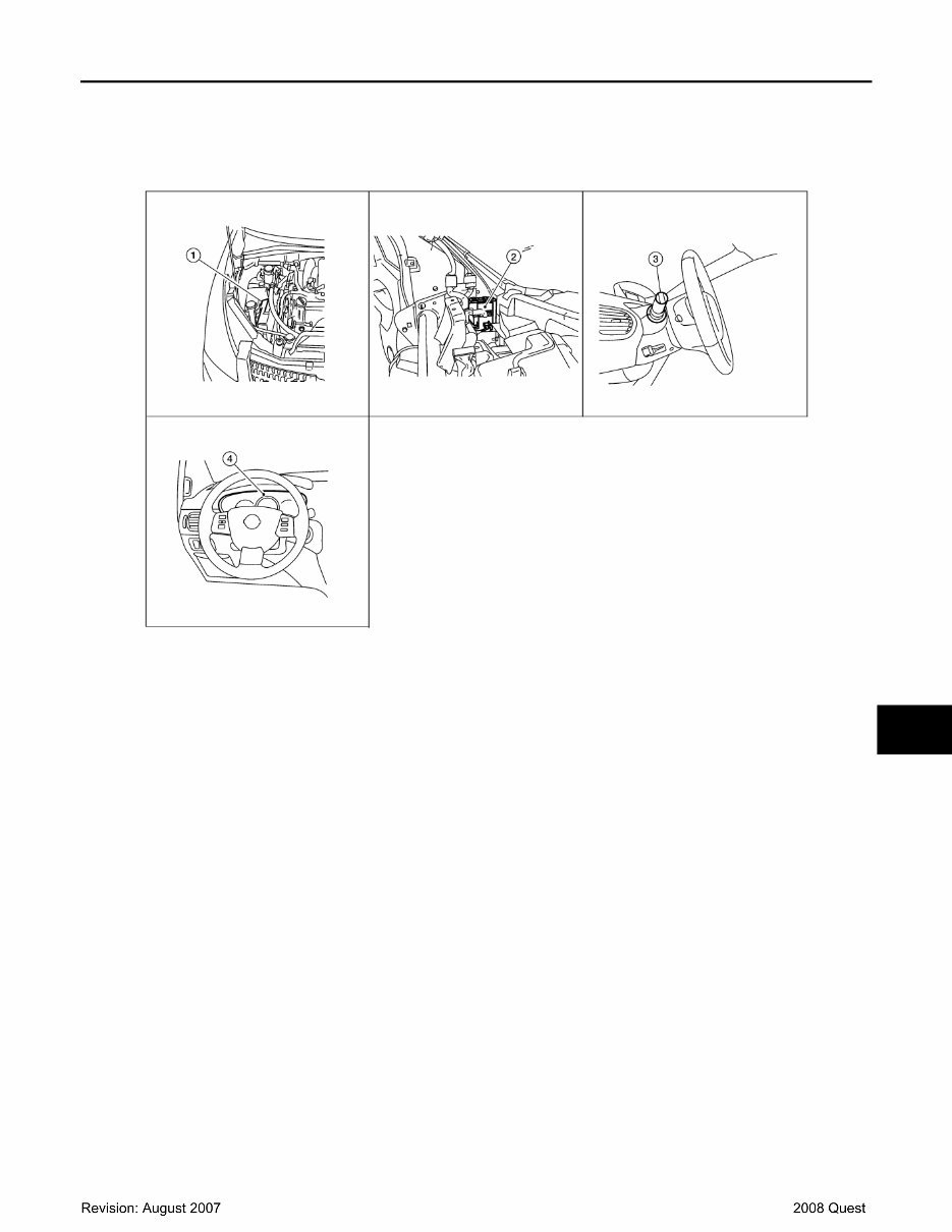
HEADLAMP (FOR USA) LT-5 < SERVICE INFORMATION > C D E F G H I J L M A B LT N O P HEADLAMP (FOR USA) Component Parts and Harness Connector Location INFOID:0000000001719033 System Description INFOID:0000000001719034 Control of the headlamp system operation is dependent upon the position of the combination switch (lighting switch). When the lighting switch is placed in the 2ND position, the BCM (body control module) receives input requesting the headlamps (and tail lamps) illuminate. This input is communicated to the IPDM E/R (intelligent power distribution module engine room) across the CAN communication lines. The CPU (central processing unit) of the IPDM E/R controls the headlamp high and headlamp low relay coils. When energized, these relays direct power to the respective headlamps, which then illuminate. OUTLINE Power is supplied at all times • to ignition relay, located in the IPDM E/R, and • to headlamp high relay, located in the IPDM E/R, and • to headlamp low relay, located in the IPDM E/R, and • through 50A fusible link (letter j, located in the fuse and fusible link box) • to BCM terminal 70, and • through 15A fuse (No. 34, located in the IPDM E/R) • to IPDM E/R CPU, and • through 15A fuse (No. 41, located in the IPDM E/R) • to IPDM E/R CPU, and • through 15A fuse [No. 3, located in the fuse block (J/B)] • to BCM terminal 57, and • through 15A fuse [No. 19, located in the fuse block (J/B)] • to combination meter terminal 40. With the ignition switch in the ON or START position, power is supplied • to ignition relay, located in the IPDM E/R, and 1. IPDM E/R 2. BCM M18, M20 (view with instru- ment panel removed) 3. Combination switch (lighting switch) M28 4. Combination meter M24 WKIA5259E
You're Reading a Preview
What's Included?
Lifetime Access
Fast Download Speeds
Offline Viewing
Access Contents & Bookmarks
Full Search Facility
Print one or all pages of your manual
$36.99
2008 Nissan Quest Service & Repair Manual Software
The 2008 Nissan Quest Service & Repair Manual is a comprehensive guide suitable for both professional mechanics and DIY enthusiasts. It provides detailed instructions and diagrams to aid in the maintenance, troubleshooting, and repair of the 2008 Nissan Quest models, including Nissan Quest S, Nissan Quest SE, and Nissan Quest SL.
With this manual, you can easily access step-by-step procedures for various systems and components, including the engine, transmission, electrical, suspension, and more. Whether you are a DIY enthusiast or a professional mechanic, this manual is designed to assist you in keeping your Nissan Quest in optimal condition.
Key features of the 2008 Nissan Quest Service & Repair Manual:
Comprehensive instructions for maintenance, repair, and service
Detailed diagrams and illustrations
Easy-to-follow step-by-step procedures
Clear identification of parts and components
System and component descriptions
Troubleshooting guides
Electrical wiring diagrams
Don't let unexpected issues with your Nissan Quest ruin your plans. With the 2008 Nissan Quest Service & Repair Manual, you'll have the knowledge and guidance to handle any maintenance or repair task with confidence.
Reviews
Q&A
Recently Viewed
5,521,897Happy Clients
2,594,462eManuals
1,120,453Trusted Sellers
15Years in Business
Price:
Actual Price:
2008 Nissan Quest Service & Repair Manual Software