ACC-1 ENGINE C D E F G H I J K L M SECTION ACC A ACC N O P CONTENTS ACCELERATOR CONTROL SYSTEM PRECAUTION .............................................. 2 PRECAUTIONS .................................................. 2 Precaution for Supplemental Restraint System (SRS) "AIR BAG" and "SEAT BELT PRE-TEN- SIONER" .................................................................. 2 REMOVAL AND INSTALLATION ............... 3 ACCELERATOR CONTROL SYSTEM .............. 3 Component .............................................................. 3 Removal and Installation ......................................... 4 SERVICE DATA AND SPECIFICATIONS (SDS) ............................................................ 6 SERVICE DATA AND SPECIFICATIONS (SDS) .................................................................. 6 Accelerator Control .................................................. 6
ACC-2 < PRECAUTION > PRECAUTIONS PRECAUTION PRECAUTIONS Precaution for Supplemental Restraint System (SRS) "AIR BAG" and "SEAT BELT PRE-TENSIONER" INFOID:0000000001653268 The Supplemental Restraint System such as “AIR BAG” and “SEAT BELT PRE-TENSIONER”, used along with a front seat belt, helps to reduce the risk or severity of injury to the driver and front passenger for certain types of collision. This system includes seat belt switch inputs and dual stage front air bag modules. The SRS system uses the seat belt switches to determine the front air bag deployment, and may only deploy one front air bag, depending on the severity of a collision and whether the front occupants are belted or unbelted. Information necessary to service the system safely is included in the SRS and SB section of this Service Man- ual. WARNING: • To avoid rendering the SRS inoperative, which could increase the risk of personal injury or death in the event of a collision which would result in air bag inflation, all maintenance must be performed by an authorized NISSAN/INFINITI dealer. • Improper maintenance, including incorrect removal and installation of the SRS, can lead to personal injury caused by unintentional activation of the system. For removal of Spiral Cable and Air Bag Module, see the SRS section. • Do not use electrical test equipment on any circuit related to the SRS unless instructed to in this Service Manual. SRS wiring harnesses can be identified by yellow and/or orange harnesses or har- ness connectors.
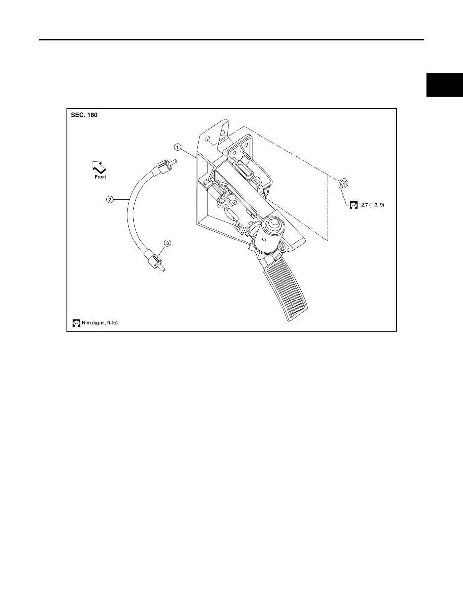
ACCELERATOR CONTROL SYSTEM ACC-3 < REMOVAL AND INSTALLATION > C D E F G H I J K L M A ACC N P O REMOVAL AND INSTALLATION ACCELERATOR CONTROL SYSTEM Component INFOID:0000000001653269 Adjustable Accelerator Pedal WBIA0628E 1. Adjustable accelerator pedal assembly 2. Adjustable brake pedal cable 3. Adjustable brake pedal cable lock tab (part of the cable)
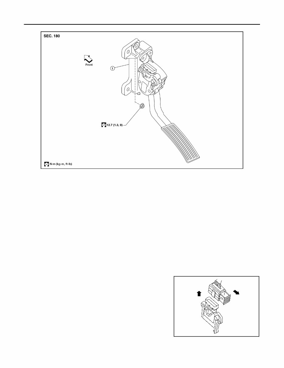
ACC-4 < REMOVAL AND INSTALLATION > ACCELERATOR CONTROL SYSTEM Non-adjustable Accelerator Pedal CAUTION: • Before removal and installation, the adjustable accelerator and brake pedals must be in the front- most position, if equipped. This is to align the base position of the accelerator and brake pedals. • Do not disassemble the accelerator pedal assembly. • Do not remove the accelerator pedal position sensor from the accelerator pedal bracket. • Do not disassemble the accelerator pedal adjusting mechanism. • Avoid damage from dropping the accelerator pedal assembly during handling. • Keep the accelerator pedal assembly away from water. Removal and Installation INFOID:0000000001653270 REMOVAL FOR ADJUSTABLE ACCELERATOR PEDAL 1. Move the accelerator and brake pedals to the frontmost position. 2. Turn the ignition switch OFF and disconnect the negative battery terminal. 3. Disconnect the adjustable pedal electric motor electrical connector. 4. Disconnect the adjustable pedal electric motor memory electrical connector, if equipped. 5. Disconnect the accelerator position sensor electrical connector. a. Pull the connector lock back to unlock the connector from the accelerator pedal position sensor as shown. b. Pull up on the connector to disconnect it from the accelerator pedal position sensor as shown. WBIA0629E 1. Non-adjustable accelerator pedal assembly LBIA0333E
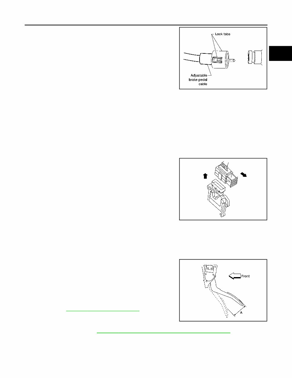
ACCELERATOR CONTROL SYSTEM ACC-5 < REMOVAL AND INSTALLATION > C D E F G H I J K L M A ACC N P O 6. Disconnect the adjustable brake pedal cable from the adjustable accelerator pedal. • Release the two lock tabs, then pull the adjustable brake pedal cable to disconnect it from the adjustable accelerator pedal. 7. Remove the two upper and one lower accelerator pedal nuts. 8. Remove the adjustable accelerator pedal assembly. CAUTION: • Do not disassemble the accelerator pedal assembly. • Do not remove the accelerator pedal position sensor from the accelerator pedal bracket. • Do not disassemble the accelerator pedal adjusting mechanism. • Avoid damage from dropping the accelerator pedal assembly during handling. • Keep the accelerator pedal assembly away from water. REMOVAL FOR NON-ADJUSTABLE ACCELERATOR PEDAL 1. Disconnect the negative battery terminal. 2. Disconnect the accelerator position sensor electrical connector. a. Pull the connector lock back to unlock the connector from the accelerator pedal position sensor as shown. b. Pull up on the connector to disconnect it from the accelerator pedal position sensor as shown. 3. Remove the two upper and one lower accelerator pedal nuts. 4. Remove the accelerator pedal assembly. CAUTION: • Do not disassemble the accelerator pedal assembly. • Do not remove the accelerator pedal position sensor from the accelerator pedal bracket. • Avoid damage from dropping the accelerator pedal assembly during handling. • Keep the accelerator pedal assembly away from water. INSTALLATION Installation is in the reverse order of removal. INSPECTION AFTER INSTALLATION • Check that the accelerator pedal moves smoothly within the speci- fied range. • Check that the accelerator pedal smoothly returns to the original position. • Perform an electrical inspection of the accelerator pedal position sensor. Refer to EC-670, " Component Inspection " . CAUTION: When the harness connector of the accelerator pedal position sensor is disconnected, perform ″Accelerator Pedal Released Position Learning″. Refer to EC-497, " Accelerator Pedal Released Position Learning " . LFIA0233E LBIA0333E Accelerator pedal - total pedal applied stroke “A” : 48 mm (1.89 in) LBIA0434E
The 2008 Nissan Pathfinder Service & Repair Manual is a comprehensive and easy-to-use repair manual that provides step-by-step instructions, clear images, and exploded-view illustrations for troubleshooting and replacing parts on your vehicle. Whether you are a professional mechanic or a DIY enthusiast, this manual is an essential tool for maintaining the durability and reliability of your vehicle.
Regular maintenance is crucial for any vehicle, and with this manual, you'll have access to the manufacturer's recommended troubleshooting charts and replacement procedures. No need to spend hours flipping through pages or trying to decipher confusing diagrams. Everything you need to know is right at your fingertips.
Gone are the days of greasy, torn, or lost pages. You can easily carry this digital manual with you on any electronic device, including your PC, Mac, smartphone, or tablet. It is compatible with pretty much any device, and all you need is Adobe Reader (which you can download for free) to access it.
But don't worry, if you prefer a physical copy, you can easily print out the manual as well. This makes it convenient to have on hand in the garage or to take with you on the go.
Overall, the 2008 Nissan Pathfinder Service & Repair Manual is an essential tool for anyone who wants to save on repair costs, increase vehicle reliability, and have the confidence to tackle any maintenance task. So why wait? Get your hands on this repair manual and take control of your vehicle's upkeep today.