ACC-1 ENGINE C D E F G H I J K L M SECTION ACC A ACC N O P CONTENTS ACCELERATOR CONTROL SYSTEM PRECAUTION .............................................. 2 PRECAUTIONS .................................................. 2 Precaution for Supplemental Restraint System (SRS) "AIR BAG" and "SEAT BELT PRE-TEN- SIONER" .................................................................. 2 REMOVAL AND INSTALLATION ............... 3 ACCELERATOR CONTROL SYSTEM .............. 3 Exploded View ......................................................... 3 Removal and Installation ......................................... 3 Inspection ................................................................ 4 SERVICE DATA AND SPECIFICATIONS (SDS) ............................................................ 5 SERVICE DATA AND SPECIFICATIONS (SDS) .................................................................. 5 Accelerator Pedal .................................................... 5 Revision: March 2012 2012 NV
ACC-2 < PRECAUTION > PRECAUTIONS PRECAUTION PRECAUTIONS Precaution for Supplemental Restraint System (SRS) "AIR BAG" and "SEAT BELT PRE-TENSIONER" INFOID:0000000006751588 The Supplemental Restraint System such as “AIR BAG” and “SEAT BELT PRE-TENSIONER”, used along with a front seat belt, helps to reduce the risk or severity of injury to the driver and front passenger for certain types of collision. This system includes seat belt switch inputs and dual stage front air bag modules. The SRS system uses the seat belt switches to determine the front air bag deployment, and may only deploy one front air bag, depending on the severity of a collision and whether the front occupants are belted or unbelted. Information necessary to service the system safely is included in the SR and SB section of this Service Man- ual. WARNING: • To avoid rendering the SRS inoperative, which could increase the risk of personal injury or death in the event of a collision which would result in air bag inflation, all maintenance must be performed by an authorized NISSAN/INFINITI dealer. • Improper maintenance, including incorrect removal and installation of the SRS, can lead to personal injury caused by unintentional activation of the system. For removal of Spiral Cable and Air Bag Module, see the SR section. • Do not use electrical test equipment on any circuit related to the SRS unless instructed to in this Service Manual. SRS wiring harnesses can be identified by yellow and/or orange harnesses or har- ness connectors. PRECAUTIONS WHEN USING POWER TOOLS (AIR OR ELECTRIC) AND HAMMERS WARNING: • When working near the Airbag Diagnosis Sensor Unit or other Airbag System sensors with the Igni- tion ON or engine running, DO NOT use air or electric power tools or strike near the sensor(s) with a hammer. Heavy vibration could activate the sensor(s) and deploy the air bag(s), possibly causing serious injury. • When using air or electric power tools or hammers, always switch the Ignition OFF, disconnect the battery, and wait at least 3 minutes before performing any service. Revision: March 2012 2012 NV
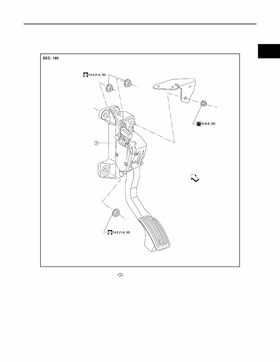
ACCELERATOR CONTROL SYSTEM ACC-3 < REMOVAL AND INSTALLATION > C D E F G H I J K L M A ACC N P O REMOVAL AND INSTALLATION ACCELERATOR CONTROL SYSTEM Exploded View INFOID:0000000007258417 Removal and Installation INFOID:0000000006751589 CAUTION: • Do not disassemble the accelerator pedal assembly. • Do not remove the accelerator pedal position sensor from the accelerator pedal bracket. • Avoid damage from dropping the accelerator pedal assembly during handling. • Keep the accelerator pedal assembly away from water. REMOVAL 1. Turn the ignition switch OFF and disconnect the negative battery terminal. 2. Disconnect the harness connector from the accelerator pedal position sensor. 3. Remove the wiring harness bracket nut and position the wiring harness bracket aside. ALBIA0697GB 1. Accelerator pedal assembly Front Revision: March 2012 2012 NV
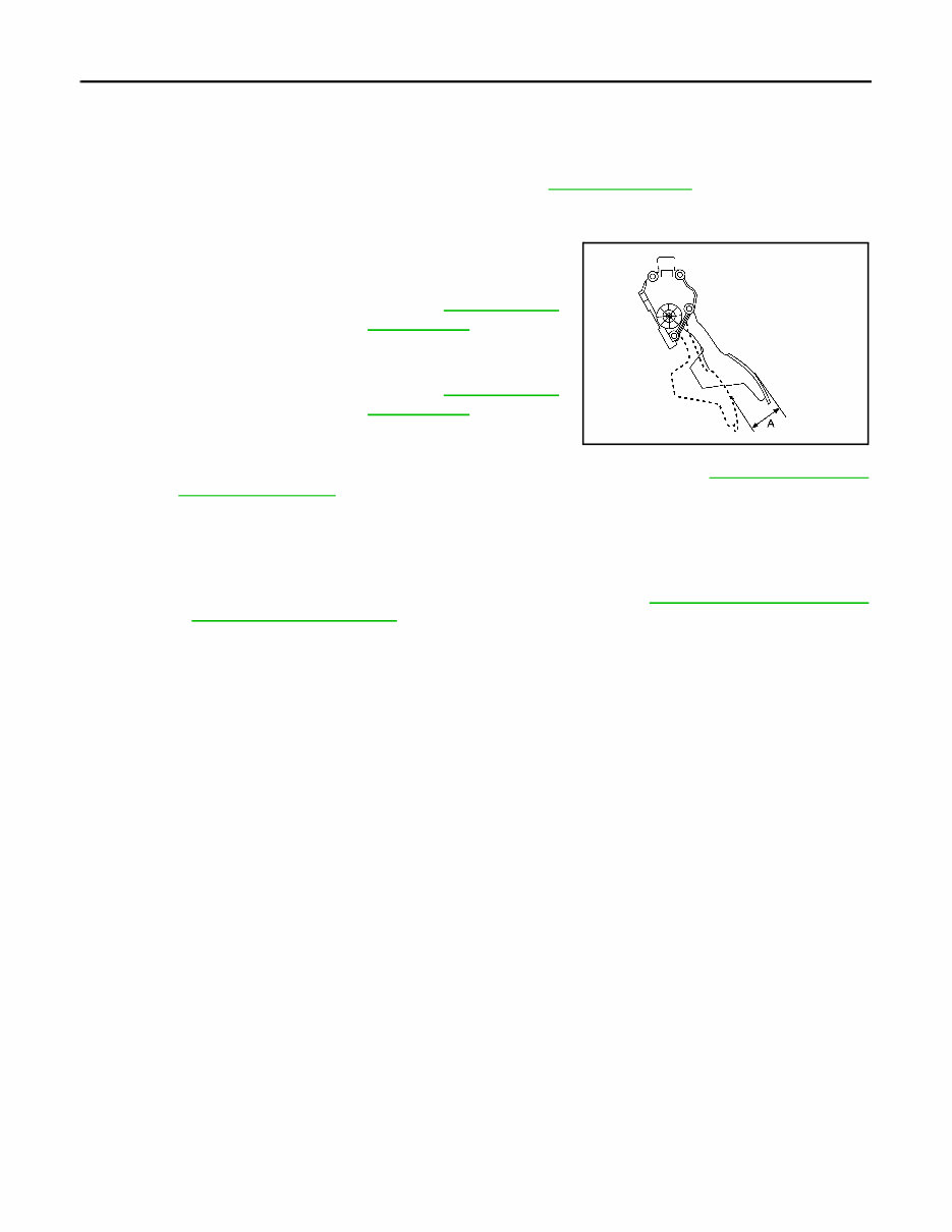
ACC-4 < REMOVAL AND INSTALLATION > ACCELERATOR CONTROL SYSTEM 4. Remove the two upper and one lower accelerator pedal nuts. 5. Remove the accelerator pedal assembly. INSTALLATION Installation is in the reverse order of removal. • Perform inspection of the accelerator pedal assembly. Refer to ACC-4, "Inspection" . Inspection INFOID:0000000007258416 • Check that the accelerator pedal moves smoothly within the speci- fied range. • Check the accelerator pedal height. • Depress and release the accelerator pedal to check that it returns quickly and smoothly to the original released position. • Perform an electrical inspection of the accelerator pedal position sensor. Refer to EC-133, "Description" (VQ40DE), EC-570, "Description" (VK56DE). CAUTION: • The accelerator pedal shall operate smoothly without catching, when the pedal operating force is released. The pedal shall return smoothly to the fully raised position. The spring shall be free from damage. • When ever the harness connector of the accelerator pedal position sensor is disconnected, per- form ″Accelerator Pedal Released Position Learning″. Refer to EC-133, "Work Procedure" (VQ40DE), EC-570, "Work Procedure" (VK56DE). Accelerator pedal stroke (A) : Refer to ACC-5, "Accel- erator Pedal" . Accelerator pedal height : Refer to ACC-5, "Accel- erator Pedal" . ALBIA0168GB Revision: March 2012 2012 NV
SERVICE DATA AND SPECIFICATIONS (SDS) ACC-5 < SERVICE DATA AND SPECIFICATIONS (SDS) C D E F G H I J K L M A ACC N P O SERVICE DATA AND SPECIFICATIONS (SDS) SERVICE DATA AND SPECIFICATIONS (SDS) Accelerator Pedal INFOID:0000000006751590 Unit: mm (in) Accelerator pedal stroke (A) 48.7 (1.92) Accelerator pedal height 146 ± 5 (5.7 ± 0.20) ALBIA0168GB Revision: March 2012 2012 NV
The 2014 Nissan NV200 Taxi Service & Repair Manual is the ultimate guide for DIY vehicle maintenance. It contains every troubleshooting and replacement procedure recommended by the manufacturer, making it an essential tool for keeping your vehicle in top condition.
With step-by-step instructions, clear images, and exploded-view illustrations, this manual provides all the necessary information for fixing any problem with your vehicle. No need to waste time flipping through hundreds of pages or searching for specific information; everything you need is conveniently organized in one place.
And with its compatibility on various electronic devices, including computers, smartphones, and tablets, you can easily access the manual wherever you go. Plus, with the option to print it out, you can have a physical copy to refer to in your garage.
Regular maintenance is crucial for prolonging the durability of your vehicle, and this manual makes it easier than ever. Keep your car running smoothly, save on costly repairs, and have peace of mind knowing you have all the necessary information at your fingertips.
So why wait? Get your hands on the 2014 Nissan NV200 Taxi Service & Repair Manual and take control of your vehicle's maintenance today.
Contains troubleshooting and replacement procedures recommended by the manufacturer
Step-by-step instructions, clear images, and exploded-view illustrations
Compatible with various electronic devices
Option to print physical copy
Easy to access and convenient to use
Essential for maintaining vehicle durability and reliability