2016 Nissan NV200 Compact Cargo Van Service & Repair Manual
What's Included?
Lifetime Access
Fast Download Speeds
Online & Offline Access
Access PDF Contents & Bookmarks
Full Search Facility
Print one or all pages of your manual
Precaution for Supplemental Restraint System (SRS) "AIR BAG" and "SEAT BELT PRE-TENSIONER" The Supplemental Restraint System such as “AIR BAG” and “SEAT BELT PRE-TENSIONER”, used along with a front seat belt, helps to reduce the risk or severity of injury to the driver and front passenger for certain types of collision. Information necessary to service the system safely is included in the SR and SB section of this Service Manual. WARNING: To avoid rendering the SRS inoperative, which could increase the risk of personal injury or death in the event of a collision which would result in air bag inflation, it is recommended that all maintenance and repair be performed by an authorized NISSAN/INFINITI dealer. Improper repair, including incorrect removal and installation of the SRS, can lead to personal injury caused by unintentional activation of the system. For removal of Spiral Cable and Air Bag Module, see the SR section. Do not use electrical test equipment on any circuit related to the SRS unless instructed to in this Service Manual. SRS wiring harnesses can be identified by yellow and/or orange harnesses or harness connectors. PRECAUTIONS WHEN USING POWER TOOLS (AIR OR ELECTRIC) AND HAMMERS WARNING: When working near the Air Bag Diagnosis Sensor Unit or other Air Bag System sensors with the Ignition ON or engine running, DO NOT use air or electric power tools or strike near the sensor(s) with a hammer. Heavy vibration could activate the sensor(s) and deploy the air bag(s), possibly causing serious injury. When using air or electric power tools or hammers, always switch the Ignition OFF, disconnect the battery or batteries, and wait at least three minutes before performing any service.
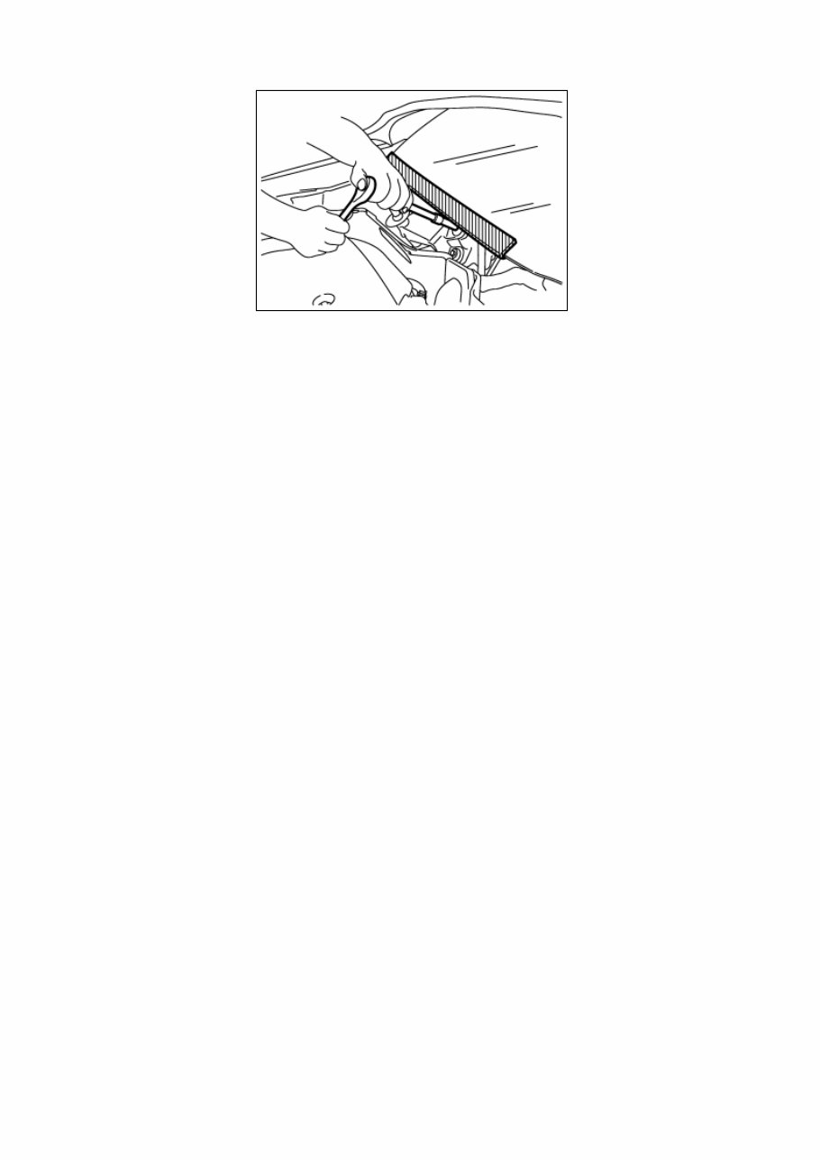
Precaution for Procedure without Cowl Top Cover When performing the procedure after removing cowl top cover, cover the lower end of windshield with urethane, etc to prevent damage to windshield. NISZ0000000013039614-01-PIIB3706J
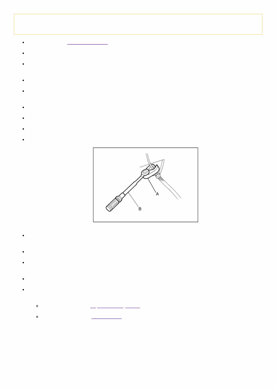
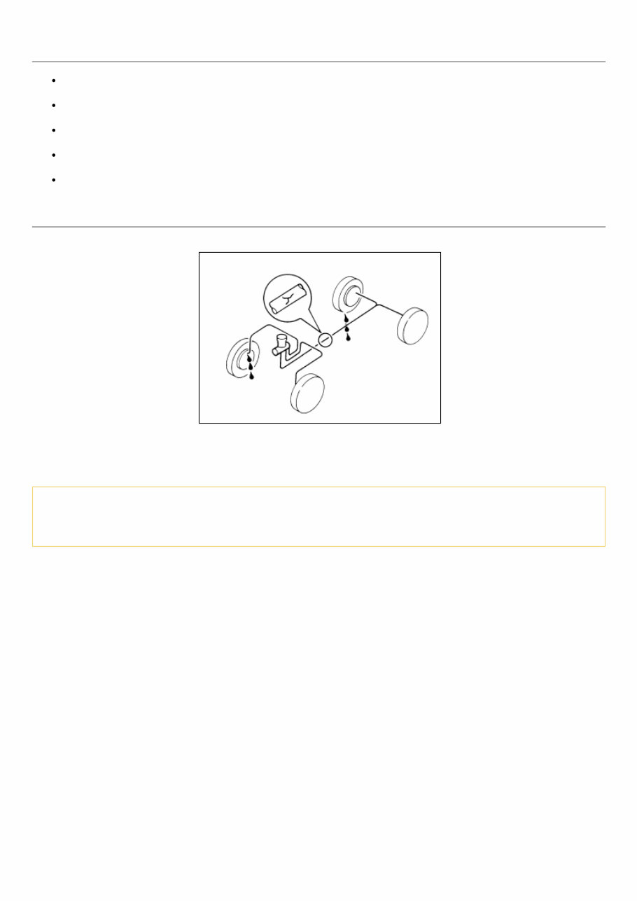
Precaution for Brake System WARNING: Clean any dust from the front brake and rear brake with a vacuum dust collector. Do not blow with compressed air. Brake fluid: Refer to Fluids and Lubricants. Do not reuse drained brake fluid. Do not spill or splash brake fluid on painted surfaces. Brake fluid may damage paint. If brake fluid is splashed on painted areas, wash it away with water immediately. Always confirm the specified tightening torque when installing the brake pipes. After pressing the brake pedal more deeply or harder than normal driving, such as air bleeding, check each item of brake pedal. Adjust brake pedal if it is outside the standard value. Always clean with new brake fluid when cleaning the brake caliper and other components. Do not use mineral oils such as gasoline or light oil to clean. They may damage rubber parts and cause improper operation. Always loosen the brake tube flare nut with a flare nut wrench. Tighten the brake tube flare nut to the specified torque with a crowfoot (A) and a torque wrench (B). NISZ0000000013039615-01-JPFIA0001ZZ Brake system is an important safety part. If a brake fluid leak is detected, always disassemble the affected part. If a malfunction is detected, replace part with a new one. Always connect the battery terminals when moving the vehicle. Turn the ignition switch OFF and disconnect the hydraulic booster assembly harness connector or the battery negative terminal before performing the work. Check that no brake fluid leaks are present after replacing the parts. Burnish the brake contact surfaces after refinishing or replacing rotors, after replacing pads, or if a soft pedal occurs at very low mileage. Front disc brake: Refer to Inspection and Adjustment. Rear drum brake: Refer to Brake Burnishing.
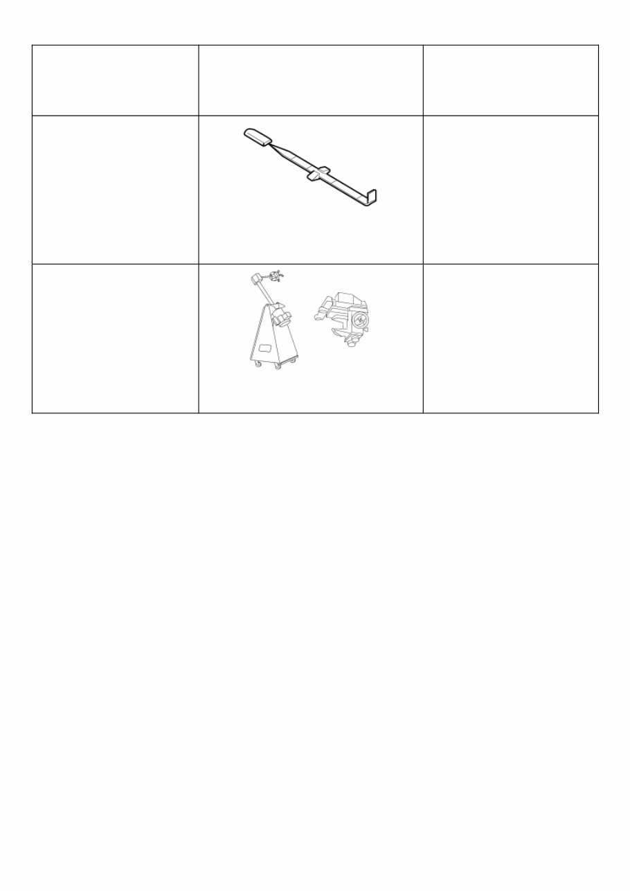
Special Service Tool The actual shape of the tools may differ from those illustrated here. Tool number (TechMate No.) Tool name Description — (J-46532) Brake height tool NISZ0000000013039616-01- LFIA0227E Measuring brake pedal height 38-PFM92 ( — ) ProCut™ PFM Series Lathe NISZ0000000013039616-02- ALFIA0092ZZ Refinishing rotors
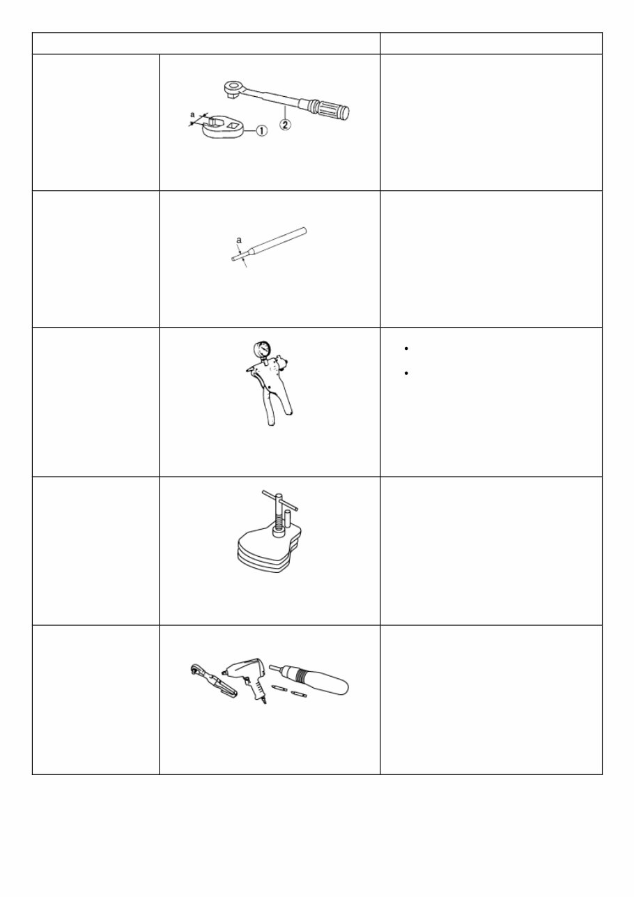
Commercial Service Tool Tool name Description 1. Flare nut crowfoot 2. Torque wrench NISZ0000000013039617-01-NT360 Tightening brake tube flare nuts a: 10 mm (0.39 in)/12 mm (0.47 in) Pin punch NISZ0000000013039617-02-NT410 Removing and installing reservoir tank a: 4 mm (0.16 in) Vacuum pump NISZ0000000013039617-03- ZZC1313D Air tight Inspection of check valve Brake caliper wrench NISZ0000000013039617-04- NNFIA0040ZZ Return the piston Power tool NISZ0000000013039617-05- PIIB1407E Loosening nuts, screws and bolts
Inspection BRAKE FLUID LEVEL Check that the fluid level in the sub tank is within the specified range (MAX – MIN lines). Visually check for any brake fluid leaks around the sub tank, hose and reservoir tank. Check the brake system for any leaks if the fluid level is extremely low (lower than MIN). Check the brake system for fluid leaks if the warning lamp remains illuminated even after the parking brake is released. Check the sub tank for the mixing of foreign matter (e.g. dust) and oils other than brake fluid. BRAKE LINE 1 Check brake line (tubes and hoses) for cracks, deterioration or other damage. Replace any damaged parts. NISZ0000000013039620-01-SBR389C 2 Depress the brake pedal with a force of 785 N (80.1 kg, 176.5 lb) and hold down the pedal for approximately 5 seconds with the engine running. Check for any fluid leaks. CAUTION: Retighten the applicable connection to the specified torque and repair any abnormal (damaged, worn or deformed) part if any brake fluid leaks are present.
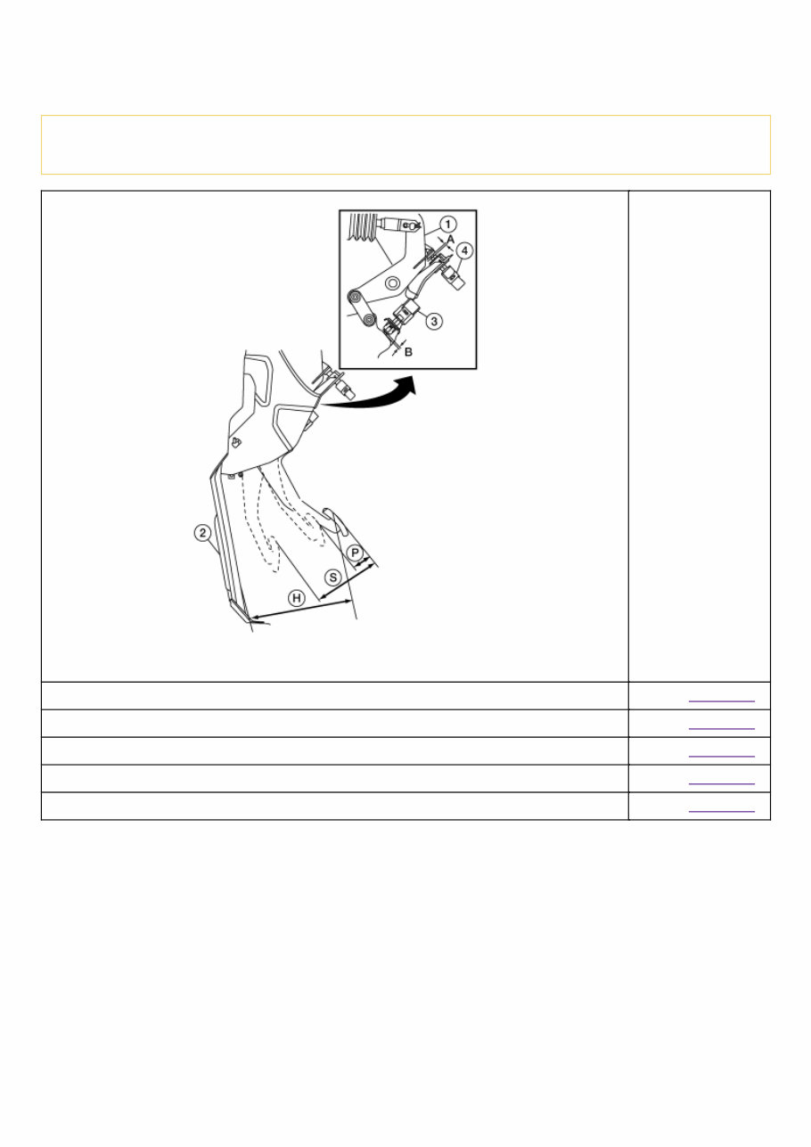
Inspection Inspect the brake pedal height (H) from the floor using Tool. Tool number : — (J-46532) CAUTION: Check the brake pedal height with the floor trim removed. NISZ0000000013039619-01-ALFIA0406ZZ Brake pedal height (H) from dash lower panel (2) Refer to Brake Pedal. Clearance (A) between brake pedal bracket (1) and brake pedal position switch (4) contact ends Refer to Brake Pedal. Clearance (B) between brake pedal bracket (1) and stop lamp switch (3) contact ends Refer to Brake Pedal. Brake pedal full stroke (S) Refer to Brake Pedal. Brake pedal play (P) Refer to Brake Pedal.
Inspection OPERATION Depress the brake pedal several times at 5-second intervals with the engine stopped. Start the engine with the brake pedal fully depressed. Check that the clearance between brake pedal and dash lower panel decreases. AIR TIGHT 1 Run the engine for 1 minute to apply vacuum to the brake booster, and stop the engine. Then depress the brake pedal several times at 5-second intervals until the accumulated vacuum is released to atmospheric pressure. Check that the clearance between brake pedal and dash lower panel gradually increases each time the brake pedal is depressed when performing this operation. 2 Depress the brake pedal with the engine running. Then stop the engine while holding down the brake pedal. Check that the brake pedal stroke does not change after holding down the brake pedal for 30 seconds or more. INSPECTION BEFORE REMOVAL Air Tight CAUTION: Check the air tight condition when the master cylinder and the brake booster is installed. 1 With a handy vacuum pump, apply vacuum pressure of −66.7 kPa (−500 mmHg, −19.69 inHg–) to the brake booster. 2 If the air tight condition cannot be maintained, perform the following operation. a Check that no dirt and dust are present on the brake booster and brake master cylinder mating faces. Clean it if necessary. b Check the seal on the brake master cylinder. If anything is found, replace the seal. c Check the air tight condition again. If the condition still cannot be maintained, replace the brake booster.
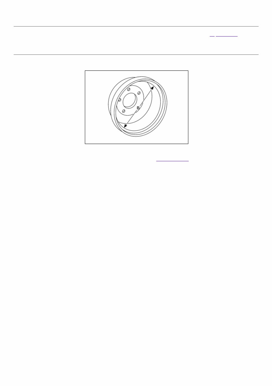
Inspection APPEARANCE Check surface of brake drum for uneven wear, cracks and serious damage. Replace it if necessary. Refer to Exploded View. INSPECTION OF BRAKE DRUM INNER DIAMETER Check inner diameter (B) of the brake drum. NISZ0000000013039626-01-AWFIA0970ZZ (B) : Refer to Rear Drum Brake.
Inspection INSPECTION OF BRAKE LINING 1 Check brake lining wear thickness (A) from an inspection hole on back plate. Check using a scale if necessary. NISZ0000000013039625-01-SBR021A (A) : Refer to Rear Drum Brake.
The 2016 Nissan NV200 Compact Cargo Van Service & Repair Manual is a comprehensive and user-friendly repair manual that allows vehicle owners to easily troubleshoot and fix problems on their own. With step-by-step instructions, clear images, and exploded-view illustrations, this manual contains every procedure recommended by the manufacturer.
Even with its unquestionable durability, regular maintenance is essential for keeping your vehicle in top condition. And when parts do eventually wear out, having a reliable repair manual at hand can save you time and money by providing the necessary troubleshooting charts and replacement procedures.
Say goodbye to flipping through countless pages or dealing with greasy, torn, or lost pages. With this service & repair manual, you can easily search, screenshot, or bookmark the information you need. Plus, it's compatible with various electronic devices such as PCs, Mac computers, smartphones, and tablets. And if you prefer a physical copy, simply print it out.
Don't let car troubles derail your day. Keep this manual handy, and you'll have all the information you need to maintain your 2016 Nissan NV200 Compact Cargo Van and keep it running smoothly for years to come.
Recently Viewed
5,521,897Happy Clients
2,594,462eManuals
1,120,453Trusted Sellers
15Years in Business
Price:
Actual Price:
2016 Nissan NV200 Compact Cargo Van Service & Repair Manual