HAC-1 VENTILATION, HEATER & AIR CONDITIONER C D E F G H J K L M SECTION HAC A B HAC N O P CONTENTS HEATER & AIR CONDITIONING CONTROL SYSTEM WITHOUT 7 INCH DISPLAY BASIC INSPECTION ................................... 5 DIAGNOSIS AND REPAIR WORKFLOW ......... 5 Work Flow ................................................................ 5 INSPECTION AND ADJUSTMENT .................... 7 Description & Inspection .......................................... 7 Temperature Setting Trimmer .................................. 9 Foot Position Setting Trimmer .................................. 9 Inlet Port Memory Function (FRE) ......................... 10 Inlet Port Memory Function (REC) ......................... 10 FUNCTION DIAGNOSIS ............................. 11 COMPRESSOR CONTROL FUNCTION ...........11 Description ............................................................. 11 Component Part Location ...................................... 12 Component’s Role .................................................. 14 AUTOMATIC AIR CONDITIONER SYSTEM ....15 System Diagram ..................................................... 15 System Description ................................................ 15 Component Part Location ...................................... 22 Component Description .......................................... 25 MODE DOOR CONTROL SYSTEM ..................26 System Diagram ..................................................... 26 System Description ................................................ 26 UPPER VENTILATOR DOOR CONTROL SYSTEM ............................................................28 System Diagram ..................................................... 28 System Description ................................................ 28 AIR MIX DOOR CONTROL SYSTEM ...............30 System Diagram ..................................................... 30 System Description ................................................ 30 INTAKE DOOR CONTROL SYSTEM ...............32 System Diagram ..................................................... 32 System Description .................................................32 BLOWER MOTOR CONTROL SYSTEM .......... 34 System Diagram .....................................................34 System Description .................................................34 MAGNET CLUTCH CONTROL SYSTEM ......... 36 System Diagram .....................................................36 System Description .................................................36 CAN COMMUNICATION SYSTEM ................... 37 System Description .................................................37 DIAGNOSIS SYSTEM (HVAC) ......................... 38 CONSULT-III Function ...........................................38 COMPONENT DIAGNOSIS ........................ 42 U1000 CAN COMM CIRCUIT ........................... 42 Description ..............................................................42 DTC Logic ...............................................................42 Diagnosis Procedure .............................................42 U1010 CONTROL UNIT (CAN) ......................... 43 Description ..............................................................43 DTC Logic ...............................................................43 Diagnosis Procedure ..............................................43 B257B, B257C AMBIENT SENSOR ................. 44 Description ..............................................................44 DTC Logic ...............................................................44 Diagnosis Procedure ..............................................45 Component Inspection ............................................46 B2578, B2579 IN-VEHICLE SENSOR .............. 47 Description ..............................................................47 DTC Logic ...............................................................47 Diagnosis Procedure ..............................................48 Component Inspection ............................................49 B2581, B2582 INTAKE SENSOR ..................... 50 Description ..............................................................50 DTC Logic ...............................................................50 Revision: 2008 October 2009 Murano
HAC-2 Diagnosis Procedure ............................................. 50 Component Inspection ........................................... 51 B2630, B2631 SUNLOAD SENSOR ................ 53 Description ............................................................. 53 DTC Logic .............................................................. 53 Diagnosis Procedure ............................................. 54 Component Inspection ........................................... 55 B2632, B2633 AIR MIX DOOR MOTOR (DRIVER SIDE) ................................................. 56 Description ............................................................. 56 DTC Logic .............................................................. 56 Diagnosis Procedure ............................................. 57 B2634, B2635 AIR MIX DOOR MOTOR (PAS- SENGER SIDE) ................................................. 58 Description ............................................................. 58 DTC Logic .............................................................. 58 Diagnosis Procedure ............................................. 59 B2636, B2637, B2638, B2639, B2654, B2655 MODE DOOR MOTOR ..................................... 60 Description ............................................................. 60 DTC Logic .............................................................. 60 Diagnosis Procedure ............................................. 61 B263D, B263E, B263F INTAKE DOOR MO- TOR ................................................................... 63 Description ............................................................. 63 DTC Logic .............................................................. 63 Diagnosis Procedure ............................................. 64 B2661, B2662, B2663 UPPER VENTILATOR DOOR MOTOR ................................................. 65 Description ............................................................. 65 DTC Logic .............................................................. 65 Diagnosis Procedure ............................................. 66 BLOWER MOTOR ............................................ 68 Description ............................................................. 68 Component Function Check ................................ 68 Diagnosis Procedure ............................................. 68 Component Inspection ........................................... 71 MAGNET CLUTCH ........................................... 72 Description ............................................................. 72 Component Function Check .................................. 72 Diagnosis Procedure ............................................. 72 A/C CONTROL SIGNAL CIRCUIT ................... 74 Diagnosis Procedure ............................................. 74 POWER SUPPLY AND GROUND CIRCUIT .... 75 A/C AUTO AMP. ...................................................... 75 A/C AUTO AMP. : Description ............................... 75 A/C AUTO AMP. : Component Function Check .... 75 A/C AUTO AMP. : Diagnosis Procedure ............... 75 A/C CONTROL ......................................................... 76 A/C CONTROL : Diagnosis Procedure .................. 76 A/C DISPLAY ........................................................... 77 A/C DISPLAY : Diagnosis Procedure .................... 77 ECU DIAGNOSIS ....................................... 78 ECM .................................................................. 78 Reference Value .................................................... 78 A/C AUTO AMP. ............................................... 93 Reference Value .................................................... 93 Wiring Diagram - AIR CONDITIONER CONTROL SYSTEM - .............................................................. 95 Fail-Safe ............................................................... 102 DTC Inspection Priority Chart ............................ 103 DTC Index ............................................................ 103 SYMPTOM DIAGNOSIS ........................... 105 AIR CONDITIONER CONTROL ...................... 105 Diagnosis Chart By Symptom .............................. 105 INSUFFICIENT COOLING ............................... 106 Description ........................................................... 106 Inspection procedure ........................................... 106 INSUFFICIENT HEATING ............................... 109 Description ........................................................... 109 Inspection procedure ........................................... 109 NOISE .............................................................. 112 Description ........................................................... 112 Inspection procedure ........................................... 112 MEMORY FUNCTION DOES NOT OPERATE .. 114 Description ........................................................... 114 Inspection procedure ........................................... 114 PRECAUTION ........................................... 115 PRECAUTIONS ............................................... 115 FOR USA AND CANADA ...................................... 115 FOR USA AND CANADA : Precaution for Supple- mental Restraint System (SRS) "AIR BAG" and "SEAT BELT PRE-TENSIONER" ........................ 115 FOR MEXICO ......................................................... 115 FOR MEXICO : Precaution for Supplemental Re- straint System (SRS) "AIR BAG" and "SEAT BELT PRE-TENSIONER" .............................................. 115 Precaution Necessary for Steering Wheel Rota- tion after Battery Disconnect ................................ 116 Precaution for Procedure without Cowl Top Cover . 116 Precautions For Xenon Headlamp Service .......... 116 Working with HFC-134a (R-134a) ........................ 117 General Refrigerant Precaution ........................... 117 Refrigerant Connection ........................................ 118 Service Equipment ............................................... 120 COMPRESSOR ............................................... 122 Revision: 2008 October 2009 Murano
HAC-3 C D E F G H J K L M A B HAC N O P General Precautions ............................................ 122 FLUORESCENT LEAK DETECTOR .............. 123 General Precautions ............................................ 123 WITH 7 INCH DISPLAY BASIC INSPECTION ................................ 124 DIAGNOSIS AND REPAIR WORKFLOW ...... 124 Work Flow ............................................................ 124 INSPECTION AND ADJUSTMENT ................. 126 Description & Inspection ...................................... 126 Temperature Setting Trimmer .............................. 128 Foot Position Setting Trimmer .............................. 128 Inlet Port Memory Function (FRE) ....................... 129 Inlet Port Memory Function (REC) ....................... 129 FUNCTION DIAGNOSIS ........................... 130 COMPRESSOR CONTROL FUNCTION ......... 130 Description ........................................................... 130 Fail-Safe ............................................................... 131 Component Part Location .................................... 131 Component’s Role ................................................ 134 AUTOMATIC AIR CONDITIONER SYSTEM .. 135 System Diagram ................................................... 135 System Description .............................................. 135 Component Part Location .................................... 141 Component Description ........................................ 144 MODE DOOR CONTROL SYSTEM ................ 145 System Diagram ................................................... 145 System Description .............................................. 145 UPPER VENTILATOR DOOR CONTROL SYSTEM .......................................................... 147 System Diagram ................................................... 147 System Description .............................................. 147 AIR MIX DOOR CONTROL SYSTEM ............. 149 System Diagram ................................................... 149 System Description .............................................. 149 INTAKE DOOR CONTROL SYSTEM ............. 151 System Diagram ................................................... 151 System Description .............................................. 151 BLOWER MOTOR CONTROL SYSTEM ........ 153 System Diagram ................................................... 153 System Description .............................................. 153 MAGNET CLUTCH CONTROL SYSTEM ....... 155 System Diagram ................................................... 155 System Description .............................................. 155 CAN COMMUNICATION SYSTEM ................. 156 System Description .............................................. 156 DIAGNOSIS SYSTEM (HVAC) ....................... 157 CONSULT-III Function ......................................... 157 COMPONENT DIAGNOSIS ...................... 161 U1000 CAN COMM CIRCUIT ......................... 161 Description ............................................................ 161 DTC Logic ............................................................. 161 Diagnosis Procedure ........................................... 161 U1010 CONTROL UNIT (CAN) ....................... 162 Description ............................................................ 162 DTC Logic ............................................................. 162 Diagnosis Procedure ............................................ 162 B257B, B257C AMBIENT SENSOR ............... 163 Description ............................................................ 163 DTC Logic ............................................................. 163 Diagnosis Procedure ............................................ 164 Component Inspection .......................................... 165 B2578, B2579 IN-VEHICLE SENSOR ............ 166 Description ............................................................ 166 DTC Logic ............................................................. 166 Diagnosis Procedure ............................................ 167 Component Inspection .......................................... 168 B2581, B2582 INTAKE SENSOR ................... 169 Description ............................................................ 169 DTC Logic ............................................................. 169 Diagnosis Procedure ............................................ 169 Component Inspection .......................................... 170 B2630, B2631 SUNLOAD SENSOR ............... 172 Description ............................................................ 172 DTC Logic ............................................................. 172 Diagnosis Procedure ............................................ 173 Component Inspection .......................................... 174 B2632, B2633 AIR MIX DOOR MOTOR (DRIVER SIDE) ............................................... 175 Description ............................................................ 175 DTC Logic ............................................................. 175 Diagnosis Procedure ............................................ 176 B2634, B2635 AIR MIX DOOR MOTOR (PAS- SENGER SIDE) ............................................... 177 Description ............................................................ 177 DTC Logic ............................................................. 177 Diagnosis Procedure ............................................ 178 B2636, B2637, B2638, B2639, B2654, B2655 MODE DOOR MOTOR .................................... 179 Description ............................................................ 179 DTC Logic ............................................................. 179 Diagnosis Procedure ............................................ 180 B263D, B263E, B263F INTAKE DOOR MO- TOR ................................................................. 182 Description ............................................................ 182 DTC Logic ............................................................. 182 Diagnosis Procedure ............................................ 183 Revision: 2008 October 2009 Murano
HAC-4 B2661, B2662, B2663 UPPER VENTILATOR DOOR MOTOR ............................................... 184 Description ............................................................ 184 DTC Logic ............................................................. 184 Diagnosis Procedure ............................................ 185 BLOWER MOTOR .......................................... 187 Description ............................................................ 187 Component Function Check ............................... 187 Diagnosis Procedure ............................................ 187 Component Inspection .......................................... 190 MAGNET CLUTCH ......................................... 191 Description ............................................................ 191 Component Function Check ................................. 191 Diagnosis Procedure ............................................ 191 POWER SUPPLY AND GROUND CIRCUIT .. 193 A/C AUTO AMP. ..................................................... 193 A/C AUTO AMP. : Description .............................. 193 A/C AUTO AMP. : Component Function Check ... 193 A/C AUTO AMP. : Diagnosis Procedure .............. 193 ECU DIAGNOSIS ...................................... 195 ECM ................................................................ 195 Reference Value ................................................... 195 A/C AUTO AMP. ............................................. 210 Reference Value ................................................... 210 Wiring Diagram - AIR CONDITIONER CONTROL SYSTEM - ............................................................. 212 Fail-Safe ............................................................... 219 DTC Inspection Priority Chart ............................ 220 DTC Index ............................................................ 220 SYMPTOM DIAGNOSIS ........................... 222 AIR CONDITIONER CONTROL ..................... 222 Diagnosis Chart By Symptom ............................... 222 INSUFFICIENT COOLING .............................. 223 Description ........................................................... 223 Inspection procedure ........................................... 223 INSUFFICIENT HEATING ............................... 226 Description ........................................................... 226 Inspection procedure ........................................... 226 NOISE .............................................................. 229 Description ........................................................... 229 Inspection procedure ........................................... 229 MEMORY FUNCTION DOES NOT OPERATE .. 231 Description ........................................................... 231 Inspection procedure ........................................... 231 PRECAUTION ........................................... 232 PRECAUTIONS ............................................... 232 FOR USA AND CANADA ...................................... 232 FOR USA AND CANADA : Precaution for Supple- mental Restraint System (SRS) "AIR BAG" and "SEAT BELT PRE-TENSIONER" ........................ 232 FOR MEXICO ......................................................... 232 FOR MEXICO : Precaution for Supplemental Re- straint System (SRS) "AIR BAG" and "SEAT BELT PRE-TENSIONER" .............................................. 232 Precaution Necessary for Steering Wheel Rota- tion after Battery Disconnect ................................ 233 Precaution for Procedure without Cowl Top Cover . 233 Precautions For Xenon Headlamp Service .......... 233 Working with HFC-134a (R-134a) ........................ 234 General Refrigerant Precaution ........................... 234 Refrigerant Connection ........................................ 235 Service Equipment ............................................... 237 COMPRESSOR ............................................... 239 General Precautions ............................................ 239 FLUORESCENT LEAK DETECTOR ............... 240 General Precautions ............................................ 240 Revision: 2008 October 2009 Murano
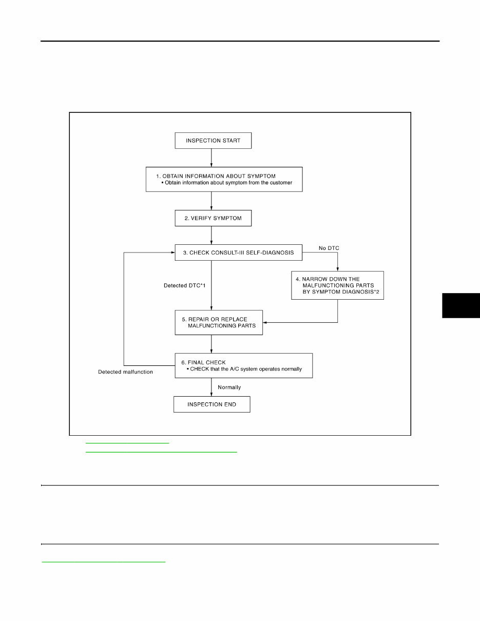
DIAGNOSIS AND REPAIR WORKFLOW HAC-5 < BASIC INSPECTION > [WITHOUT 7 INCH DISPLAY] C D E F G H J K L M A B HAC N O P BASIC INSPECTION DIAGNOSIS AND REPAIR WORKFLOW Work Flow INFOID:0000000003073006 OVERALL SEQUENCE *1: Refer to HAC-103, " DTC Index " . *2: Refer to HAC-105, " Diagnosis Chart By Symptom " . DETAILED FLOW 1.OBTAIN INFORMATION ABOUT SYMPTOM Interview the customer to obtain as much information as possible about the conditions and environment under which the malfunction occurred. >> GO TO 2. 2.VERIFY SYMPTOM Verify the symptom with operational check based on the information obtained from the customer. Refer to HAC-7, " Description & Inspection " . >> GO TO 3. JSIIA0943GB Revision: 2008 October 2009 Murano
This 2009 Nissan Murano Service & Repair Manual is the ultimate guide for owners and technicians alike. With its comprehensive coverage, it provides step-by-step instructions and detailed diagrams to help you efficiently service and repair your 2009 Nissan Murano.
Whether you are a professional mechanic or a DIY enthusiast, this manual is designed to assist you in maintaining your vehicle's optimal performance. From routine maintenance tasks to complex repairs, this manual has got you covered.
Complete and easy-to-follow instructions for all models of the 2009 Nissan Murano
Extensive troubleshooting guides to identify and resolve common issues
Clear and detailed diagrams to assist in disassembly and reassembly
Step-by-step procedures for engine, transmission, suspension, electrical, and other major systems
Comprehensive information on recommended fluids, torque specifications, and maintenance schedules
Available in convenient .PDF format for easy access on your computer, laptop, or tablet
Whether you need to change the oil, replace a component, or diagnose a problem, this 2009 Nissan Murano Service & Repair Manual is your go-to resource. Don't waste time and money at the dealership or auto repair shop – empower yourself with the knowledge and expertise to take care of your vehicle.