HAC-1 VENTILATION, HEATER & AIR CONDITIONER C D E F G H J K L M SECTION HAC A B HAC N O P CONTENTS HEATER & AIR CONDITIONING CONTROL SYSTEM AUTOMATIC AIR CONDITIONER BASIC INSPECTION ................................... 4 DIAGNOSIS AND REPAIR WORKFLOW ......... 4 Work Flow ................................................................ 4 INSPECTION AND ADJUSTMENT .................... 6 Description & Inspection .......................................... 6 Temperature Setting Trimmer .................................. 8 Foot Position Setting Trimmer .................................. 9 Inlet Port Memory Function (FRE) ........................... 9 Inlet Port Memory Function (REC) ......................... 10 FUNCTION DIAGNOSIS ............................. 11 COMPRESSOR CONTROL FUNCTION ...........11 Description ............................................................. 11 Fail-Safe ................................................................. 11 Component Part Location ...................................... 12 Component Description .......................................... 15 AUTOMATIC AIR CONDITIONER SYSTEM ....16 System Diagram ..................................................... 16 System Description ................................................ 16 Component Part Location ...................................... 23 Component Description .......................................... 26 MODE DOOR CONTROL SYSTEM ..................27 System Diagram ..................................................... 27 System Description ................................................ 27 UPPER VENTILATOR DOOR CONTROL SYSTEM ............................................................29 System Diagram ..................................................... 29 System Description ................................................ 29 AIR MIX DOOR CONTROL SYSTEM ...............31 System Diagram ..................................................... 31 System Description ................................................ 31 INTAKE DOOR CONTROL SYSTEM ...............33 System Diagram .....................................................33 System Description .................................................33 BLOWER MOTOR CONTROL SYSTEM .......... 35 System Diagram .....................................................35 System Description .................................................35 MAGNET CLUTCH CONTROL SYSTEM ......... 37 System Diagram .....................................................37 System Description .................................................37 CAN COMMUNICATION SYSTEM ................... 38 System Description .................................................38 DIAGNOSIS SYSTEM (HVAC) ......................... 39 CONSULT-III Function ...........................................39 COMPONENT DIAGNOSIS ........................ 43 U1000 CAN COMM CIRCUIT ........................... 43 Description ..............................................................43 DTC Logic ...............................................................43 Diagnosis Procedure .............................................43 U1010 CONTROL UNIT (CAN) ......................... 44 Description ..............................................................44 DTC Logic ...............................................................44 Diagnosis Procedure ..............................................44 B257B, B257C AMBIENT SENSOR ................. 45 Description ..............................................................45 DTC Logic ...............................................................45 Diagnosis Procedure ..............................................46 Component Inspection ............................................47 B2578, B2579 IN-VEHICLE SENSOR .............. 48 Description ..............................................................48 DTC Logic ...............................................................48 Diagnosis Procedure ..............................................49 Component Inspection ............................................50 B2581, B2582 INTAKE SENSOR ..................... 51 Description ..............................................................51
HAC-2 DTC Logic .............................................................. 51 Diagnosis Procedure ............................................. 51 Component Inspection ........................................... 52 B2630, B2631 SUNLOAD SENSOR ................ 54 Description ............................................................. 54 DTC Logic .............................................................. 54 Diagnosis Procedure ............................................. 54 Component Inspection ........................................... 55 B2632, B2633 AIR MIX DOOR MOTOR (DRIVER SIDE) ................................................. 57 Description ............................................................. 57 DTC Logic .............................................................. 57 Diagnosis Procedure ............................................. 58 B2634, B2635 AIR MIX DOOR MOTOR (PAS- SENGER SIDE) ................................................. 59 Description ............................................................. 59 DTC Logic .............................................................. 59 Diagnosis Procedure ............................................. 60 B2636, B2637, B2638, B2639, B2654, B2655 MODE DOOR MOTOR ..................................... 61 Description ............................................................. 61 DTC Logic .............................................................. 61 Diagnosis Procedure ............................................. 62 B263D B263E, B263F, B2656 INTAKE DOOR MOTOR ............................................................. 64 Description ............................................................. 64 DTC Logic .............................................................. 64 Diagnosis Procedure ............................................. 65 B2661, B2662, B2663 UPPER VENTILATOR DOOR MOTOR ................................................. 66 Description ............................................................. 66 DTC Logic .............................................................. 66 Diagnosis Procedure ............................................. 67 POWER SUPPLY AND GROUND CIRCUIT .... 69 Diagnosis Procedure ............................................. 69 A/C AUTO AMP. ............................................... 70 Description ............................................................. 70 Component Function Check .................................. 70 Diagnosis Procedure ............................................. 70 BLOWER MOTOR ............................................ 71 Description ............................................................. 71 Component Function Check ................................ 71 Diagnosis Procedure ............................................. 71 Component Inspection ........................................... 74 MAGNET CLUTCH ........................................... 75 Description ............................................................. 75 Component Function Check .................................. 75 Diagnosis Procedure ............................................. 75 ECU DIAGNOSIS ....................................... 77 A/C AUTO AMP. ............................................... 77 Reference Value .................................................... 77 Wiring Diagram - AIR CONDITIONER CONTROL SYSTEM - .............................................................. 79 Fail-Safe ................................................................. 86 DTC Inspection Priority Chart .............................. 87 DTC Index .............................................................. 87 SYMPTOM DIAGNOSIS ............................ 89 AIR CONDITIONER CONTROL ....................... 89 Diagnosis Chart By Symptom ................................ 89 INSUFFICIENT COOLING ................................ 90 Description ............................................................. 90 Diagnosis Procedure .............................................. 90 INSUFFICIENT HEATING ................................ 92 Description ............................................................. 92 Diagnosis Procedure .............................................. 92 NOISE ............................................................... 95 Description ............................................................. 95 Diagnosis Procedure .............................................. 95 MEMORY FUNCTION DOES NOT OPERATE ... 97 Description ............................................................. 97 Diagnosis Procedure .............................................. 97 PRECAUTION ............................................ 98 PRECAUTIONS ................................................ 98 Precaution for Supplemental Restraint System (SRS) "AIR BAG" and "SEAT BELT PRE-TEN- SIONER" ................................................................ 98 Precaution Necessary for Steering Wheel Rota- tion after Battery Disconnect .................................. 98 Working with HFC-134a (R-134a) .......................... 98 General Refrigerant Precaution ............................. 99 LHD MODELS .......................................................... 99 LHD MODELS : Refrigerant Connection ................ 99 RHD MODELS ........................................................ 101 RHD MODELS : Refrigerant Connection ............. 101 Service Equipment ............................................... 103 COMPRESSOR ............................................... 106 General Precautions ............................................ 106 LEAK DETECTION DYE ................................. 107 General Precautions ............................................ 107 PREPARATION ......................................... 108 PREPARATION ............................................... 108 Special Service Tool ............................................ 108 Commercial Service Tools ................................. 109 Sealant or/and Lubricant ...................................... 110 ON-VEHICLE REPAIR .............................. 112
HAC-3 C D E F G H J K L M A B HAC N O P PRESET SWITCH ........................................... 112 Exploded View ..................................................... 112 Removal and Installation ...................................... 112 A/C AUTO AMP. .............................................. 113 Exploded View ..................................................... 113 Removal and Installation ...................................... 113 AMBIENT SENSOR ........................................ 114 Exploded View ..................................................... 114 Removal and Installation ...................................... 114 IN-VEHICLE SENSOR .................................... 115 Exploded View ..................................................... 115 Removal and Installation ...................................... 115 INTAKE SENSOR ........................................... 116 Exploded View ..................................................... 116 Removal and Installation ...................................... 116 SUNLOAD SENSOR ....................................... 117 Exploded View ..................................................... 117 Removal and Installation ...................................... 117 REFRIGERANT PRESSURE SENSOR .......... 118 Exploded View ...................................................... 118 Removal and Installation ...................................... 118 DOOR MOTOR ................................................ 119 Exploded View ...................................................... 119 INTAKE DOOR MOTOR ......................................... 119 INTAKE DOOR MOTOR : Removal and Installa- tion ........................................................................ 119 UPPER VENTILATOR DOOR MOTOR .................. 120 UPPER VENTILATOR DOOR MOTOR : Removal and Installation ..................................................... 120 MODE DOOR MOTOR ............................................ 120 MODE DOOR MOTOR : Removal and Installation .. 120 AIR MIX DOOR MOTOR ......................................... 120 AIR MIX DOOR MOTOR : Removal and Installa- tion (LHD models) ................................................. 121 AIR MIX DOOR MOTOR : Removal and Installa- tion (RHD models) ................................................ 121
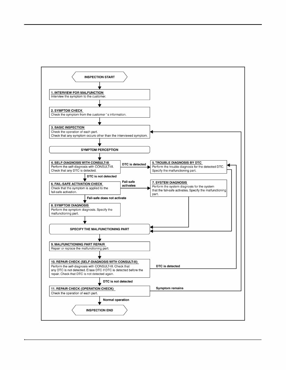
HAC-4 < BASIC INSPECTION > [AUTOMATIC AIR CONDITIONER] DIAGNOSIS AND REPAIR WORKFLOW BASIC INSPECTION DIAGNOSIS AND REPAIR WORKFLOW Work Flow INFOID:0000000004222888 OVERALL SEQUENCE DETAILED FLOW 1.INTERVIEW FOR MALFUNCTION Interview the symptom to the customer. JPLIA0313GB
DIAGNOSIS AND REPAIR WORKFLOW HAC-5 < BASIC INSPECTION > [AUTOMATIC AIR CONDITIONER] C D E F G H J K L M A B HAC N O P >> GO TO 2. 2.SYMPTOM CHECK Check the symptom from the customer's information. >> GO TO 3. 3.BASIC INSPECTION Check the operation of each part. Check that any symptom occurs other than the interviewed symptom. >> GO TO 4. 4.SELF-DIAGNOSIS WITH CONSULT-III Perform the self-diagnosis with CONSULT-III. Check that any DTC is detected. Is any DTC detected? YES >> GO TO 5. NO >> GO TO 6. 5.TROUBLE DIAGNOSIS BY DTC Perform the trouble diagnosis for the detected DTC. Specify the malfunctioning part. >> GO TO 9. 6.FAIL-SAFE ACTIVATION CHECK Check that the symptom is applied to the fail-safe activation. Does the fail-safe activate? YES >> GO TO 7. NO >> GO TO 8. 7.SYSTEM DIAGNOSIS Perform the system diagnosis for the system that the fail-safe activates. Specify the malfunctioning part. >> GO TO 9. 8.SYMPTOM DIAGNOSIS Perform the symptom diagnosis. Specify the malfunctioning part. >> GO TO 9. 9.MALFUNCTION PART REPAIR Repair or replace the malfunctioning part. >> GO TO 10. 10.REPAIR CHECK (SELF-DIAGNOSIS WITH CONSULT-III) Perform the self-diagnosis with CONSULT-III. Check that any DTC is not detected. Erase DTC if DTC is detected before the repair. Check that DTC is not detected again. Is any DTC detected? YES >> GO TO 5. NO >> GO TO 11. 11.REPAIR CHECK (OPERATION CHECK) Check the operation of each part. Does it operate normally? YES >> INSPECTION END NO >> GO TO 3.
Troubleshooting and maintaining your 2009 Nissan Murano has never been easier with this comprehensive repair manual. Whether you are a seasoned mechanic or a novice, this manual has everything you need to fix your vehicle, including step-by-step instructions, clear images, and exploded-view illustrations provided by the manufacturer.
Regular maintenance is essential to keep your vehicle running smoothly and with this manual, you can easily perform the recommended maintenance tasks. Even with proper maintenance, some parts will eventually wear out and need to be replaced. With this manual, you'll have access to the manufacturer's recommended troubleshooting charts and replacement procedures, allowing you to save money on repairs and increase your vehicle's reliability.
One of the great features of this manual is its convenience. No need to flip through hundreds of pages to find the information you need. You can easily carry it around, search for specific information, take screenshots, and bookmark pages. It's much more convenient than a traditional bound manual.
If you prefer a physical copy, you can easily print out the manual. It is compatible with any electronic device, including PC and Mac computers, smartphones, and tablets. And all you need is a free Adobe Reader to access it.
Don't let vehicle repairs and maintenance be a hassle. Get your hands on this 2009 Nissan Murano Service & Repair Manual and keep your vehicle running smoothly for years to come.
Printable: Yes
Language: English
Compatibility: PC & Mac computers, Android and Apple smartphones & tablets, and any electronic device