ACC-1 ACCELERATOR CONTROL SYSTEM B ENGINE CONTENTS C D E F G H I J K L M SECTION A ACC ACCELERATOR CONTROL SYSTEM PRECAUTIONS ......................................................... 2 Precautions for Supplemental Restraint System (SRS) “AIR BAG” and “SEAT BELT PRE-TEN- SIONER” ................................................................. 2 ACCELERATOR CONTROL SYSTEM ..................... 3 Components ............................................................ 3 Removal and Installation ......................................... 3 REMOVAL ............................................................ 3 INSTALLATION .................................................... 4 INSPECTION AFTER INSTALLATION ................. 4
ACC-2 PRECAUTIONS PRECAUTIONS PFP:00001 Precautions for Supplemental Restraint System (SRS) “AIR BAG” and “SEAT BELT PRE-TENSIONER” EBS01LRA The Supplemental Restraint System such as “AIR BAG” and “SEAT BELT PRE-TENSIONER”, used along with a front seat belt, helps to reduce the risk or severity of injury to the driver and front passenger for certain types of collision. This system includes seat belt switch inputs and dual stage front air bag modules. The SRS system uses the seat belt switches to determine the front air bag deployment, and may only deploy one front air bag, depending on the severity of a collision and whether the front occupants are belted or unbelted. Information necessary to service the system safely is included in the SRS and SB section of this Service Man- ual. WARNING: ● To avoid rendering the SRS inoperative, which could increase the risk of personal injury or death in the event of a collision which would result in air bag inflation, all maintenance must be per- formed by an authorized NISSAN/INFINITI dealer. ● Improper maintenance, including incorrect removal and installation of the SRS, can lead to per- sonal injury caused by unintentional activation of the system. For removal of Spiral Cable and Air Bag Module, see the SRS section. ● Do not use electrical test equipment on any circuit related to the SRS unless instructed to in this Service Manual. SRS wiring harnesses can be identified by yellow and/or orange harnesses or harness connectors.
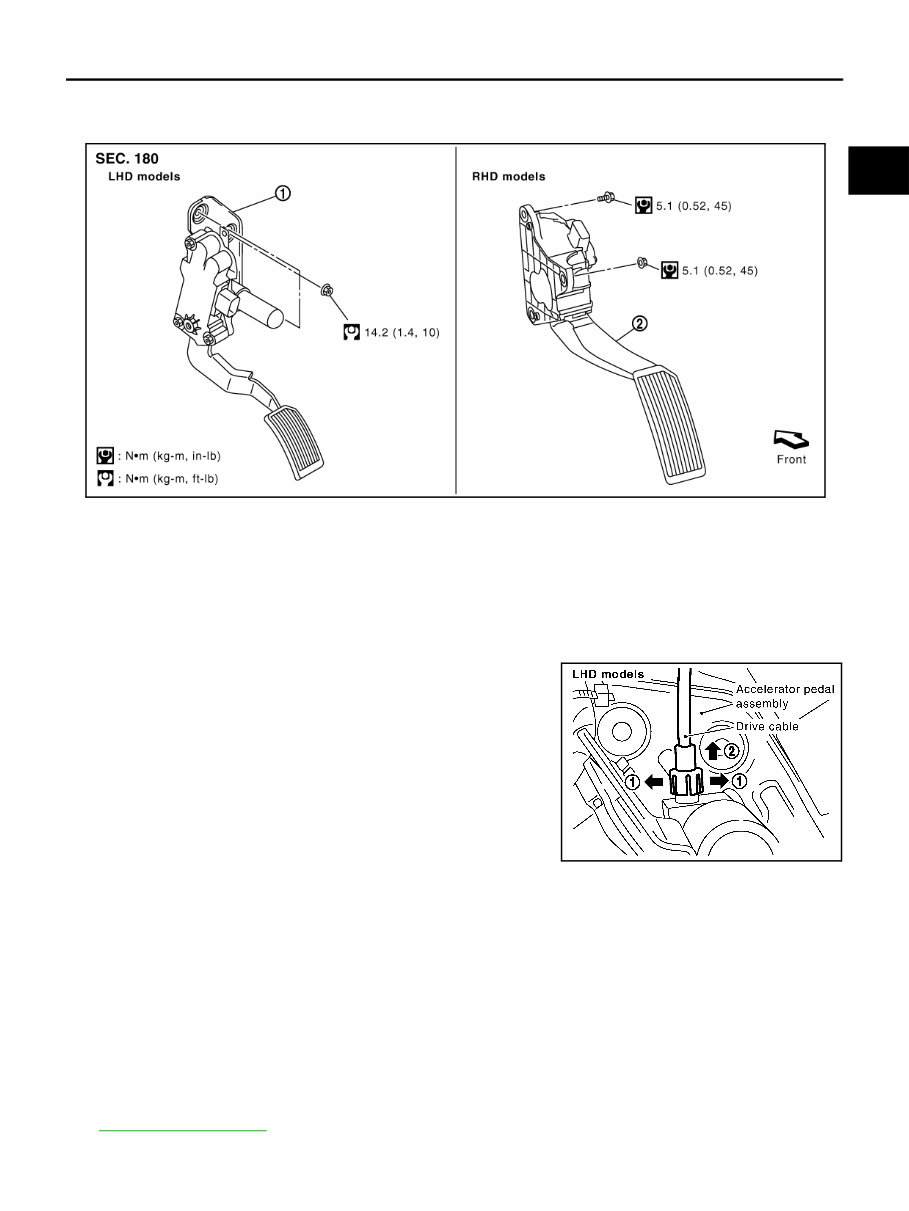
ACCELERATOR CONTROL SYSTEM ACC-3 C D E F G H I J K L M A ACC ACCELERATOR CONTROL SYSTEM PFP:18005 Components EBS01CBK Removal and Installation EBS01CAN REMOVAL 1. Move accelerator and brake pedals to the front most position (Adjustable type). 2. Turn ignition switch “OFF” and disconnect negative battery terminal. 3. Disconnect accelerator pedal position sensor harness connector. 4. Disconnect drive cable from accelerator pedal assembly (Adjustable type). ● Unlock (1) then pull (2) to disconnect drive cable. 5. Loosen nuts, and remove accelerator pedal assembly. CAUTION: ● Before removal and installation accelerator and brake pedals must be in front most position. This is to align the base position of accelerator and brake pedals (Adjustable type). ● Do not disassemble accelerator pedal assembly. Do not remove accelerator pedal position sen- sor from accelerator pedal assembly. ● Adjusting mechanism for accelerator pedal position is not able to disassemble (Adjustable type). ● Avoid impact from dropping etc. during handling. ● Be careful to keep accelerator pedal assembly away from water. NOTE: Drive cable of the adjustable type accelerator pedal assembly is a component of brake pedal. Refer to BR-6, " BRAKE PEDAL " . 1. Accelerator pedal assembly (adjustable type) 2. Accelerator pedal assembly (normal type) PBIC4220E PBIC3116E
ACC-4 ACCELERATOR CONTROL SYSTEM INSTALLATION Install in the reverse order of removal. INSPECTION AFTER INSTALLATION ● Make sure accelerator pedal moves smoothly within the whole operation range when it is fully depressed and released. ● Make sure accelerator pedal securely returns to the fully released position. ● Check operation conditions in forward and rearward movement of accelerator pedal assembly (Adjustable type). Refer to BR-6, " BRAKE PEDAL " . ● For the electrical inspection of accelerator pedal position sensor, refer to EC-615, " DTC P2138 APP SEN- SOR " . CAUTION: When harness connector of accelerator pedal position sensor is disconnected, perform “Acceler- ator Pedal Released Position Learning”. Refer to EC-68, " Accelerator Pedal Released Position Learning " .
The 2004-2007 Nissan Murano Service & Repair Manual provides complete factory-level service information for maintaining, diagnosing, and repairing all Murano models from 2004 to 2007. Designed for both professional technicians and experienced DIYers, this manual offers detailed procedures, clear illustrations, and technical specifications across all major systems and components.
With step-by-step instructions and comprehensive troubleshooting guides, it supports everything from basic maintenance to advanced diagnostics and major mechanical repairs. Whether you're working on the engine, transmission, suspension, or electrical systems, this manual delivers the precise information needed to perform repairs efficiently and correctly.
Content Overview:
Full model coverage for 2004-2007 Nissan Murano
Engine mechanical service and troubleshooting procedures
Transmission servicing and repair
Suspension, steering, and braking systems
Electrical system diagnostics with wiring diagrams
Climate control, HVAC servicing, and adjustments
Interior and exterior body repair procedures
Technical specifications, torque values, and service standards
Comprehensive troubleshooting charts and diagnostic flowcharts
This manual is an essential tool for anyone maintaining or restoring a Nissan Murano, providing the same in-depth service information trusted by dealership technicians. Fully searchable and printable for convenience, it ensures you have reliable technical support whenever needed.
Printable: Yes Language: English Compatibility: Windows, macOS, Linux, Android, iOS Requirements: PDF reader software (e.g., Adobe Reader)