CHG CHG-1 ELECTRICAL & POWER CONTROL C D E F G H I J K L B SECTION CHG A O P N CONTENTS CHARGING SYSTEM BASIC INSPECTION ................................... 2 DIAGNOSIS AND REPAIR WORKFLOW ......... 2 Work Flow (With EXP-800 NI or GR8-1200 NI) ....... 2 Work Flow (Without EXP-800 NI or GR8-1200 NI) ...... 5 SYSTEM DESCRIPTION ............................. 8 CHARGING SYSTEM ......................................... 8 System Diagram ....................................................... 8 System Description .................................................. 8 Component Description ........................................... 8 POWER GENERATION VOLTAGE VARI- ABLE CONTROL SYSTEM ................................ 9 System Diagram ....................................................... 9 System Description .................................................. 9 Component Description ............................................ 9 DTC/CIRCUIT DIAGNOSIS ........................ 10 CHARGING SYSTEM PRELIMINARY IN- SPECTION .........................................................10 Diagnosis Procedure .............................................. 10 POWER GENERATION VOLTAGE VARI- ABLE CONTROL SYSTEM OPERATION IN- SPECTION .........................................................11 Diagnosis Procedure .............................................. 11 B TERMINAL CIRCUIT .....................................13 Description ............................................................. 13 Diagnosis Procedure .............................................. 13 L TERMINAL CIRCUIT (OPEN) ........................14 Description ............................................................. 14 Diagnosis Procedure .............................................. 14 L TERMINAL CIRCUIT (SHORT) ......................16 Description ............................................................. 16 Diagnosis Procedure .............................................. 16 S TERMINAL CIRCUIT ..................................... 17 Description ..............................................................17 Diagnosis Procedure ..............................................17 WIRING DIAGRAM ..................................... 18 CHARGING SYSTEM ....................................... 18 Wiring Diagram .......................................................18 SYMPTOM DIAGNOSIS ............................. 25 CHARGING SYSTEM ....................................... 25 Symptom Table ......................................................25 PRECAUTION ............................................. 26 PRECAUTIONS ................................................. 26 Precaution for Supplemental Restraint System (SRS) "AIR BAG" and "SEAT BELT PRE-TEN- SIONER" ................................................................26 Precaution for Power Generation Voltage Variable Control System .......................................................26 PREPARATION .......................................... 27 PREPARATION ................................................. 27 Special Service Tool ...............................................27 Commercial Service Tool .......................................27 REMOVAL AND INSTALLATION .............. 28 GENERATOR .................................................... 28 Exploded View ........................................................28 Removal and Installation ........................................28 Inspection ...............................................................29 SERVICE DATA AND SPECIFICATIONS (SDS) ........................................................... 30 SERVICE DATA AND SPECIFICATIONS (SDS) ................................................................. 30 Generator ...............................................................30 Revision: August 2012 2012 Maxima
CHG-2 < BASIC INSPECTION > DIAGNOSIS AND REPAIR WORKFLOW BASIC INSPECTION DIAGNOSIS AND REPAIR WORKFLOW Work Flow (With EXP-800 NI or GR8-1200 NI) INFOID:0000000008807275 CHARGING SYSTEM DIAGNOSIS WITH EXP-800 NI OR GR8-1200 NI To test the charging system, use the following special service tools: • EXP-800 NI Battery and electrical diagnostic analyzer • GR8-1200 NI Multitasking battery and electrical diagnostic station NOTE: Refer to the applicable Instruction Manual for proper charging system diagnosis procedures. Revision: August 2012 2012 Maxima
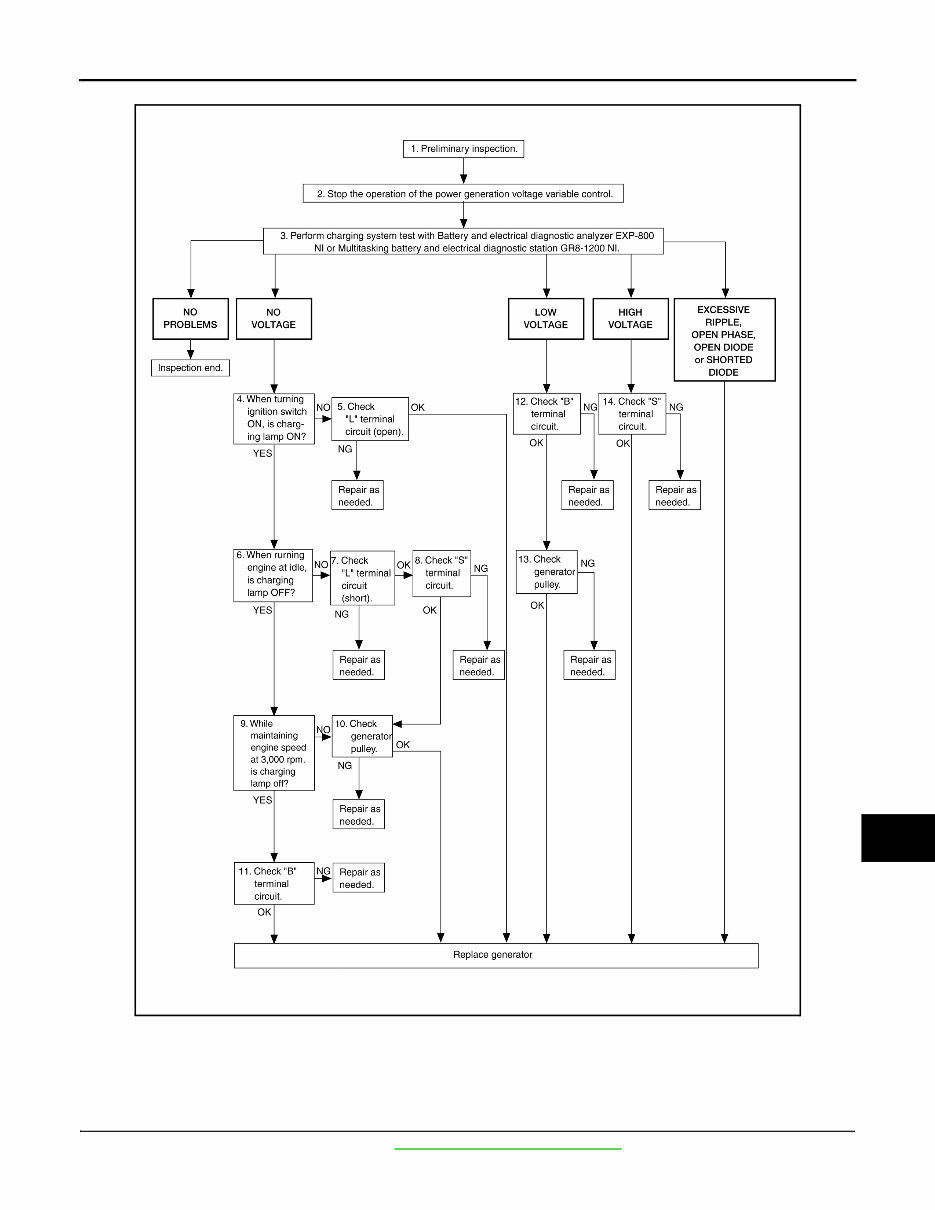
CHG DIAGNOSIS AND REPAIR WORKFLOW CHG-3 < BASIC INSPECTION > C D E F G H I J K L B A O P N OVERALL SEQUENCE DETAILED FLOW NOTE: To ensure a complete and thorough diagnosis, the battery, stater and generator test segments must be done as a set from start to finish. 1.PRELIMINARY INSPECTION Perform the preliminary inspection. Refer to CHG-10, "Diagnosis Procedure" . AWMIA1283GB Revision: August 2012 2012 Maxima
CHG-4 < BASIC INSPECTION > DIAGNOSIS AND REPAIR WORKFLOW >> GO TO 2. 2.STOP POWER GENERATION VOLTAGE VARIABLE CONTROL SYSTEM Stop the operation of the power generation voltage variable control in either of the following procedures. • After selecting “ENGINE” using CONSULT, set the DUTY value of “ALTERNATOR DUTY” to 0 % by select- ing “ALTERNATOR DUTY” of “Active Test”. Continue “Active Test” until the end of inspection. (When the DUTY value is 0 or 100 %, the normal power generation is performed according to the characteristic of the IC regulator of the generator.) • Turn the ignition switch OFF, and disconnect the battery current sensor connector. [However, DTC (P1550– P1554) of the engine might remain. After finishing the inspection, connect the battery current sensor connec- tor and erase the self diagnosis results history of the engine using CONSULT.] >> GO TO 3. 3.DIAGNOSIS WITH EXP-800 NI OR GR8-1200 NI Perform the charging system test using Multitasking battery and electrical diagnostic station GR8-1200 NI or Battery and electrical diagnostic analyzer EXP-800 NI. Refer to the applicable Instruction Manual for proper testing procedures. Test result NO PROBLEMS>>Charging system is normal and will also show “DIODE RIPPLE” test result. NO VOLTAGE>>GO TO 4. LOW VOLTAGE>>GO TO 12. HIGH VOLTAGE>>GO TO 14. EXCESSIVE RIPPLE, OPEN PHASE, OPEN DIODE or SHORTED DIODE>>Replace the generator. Refer to CHG-28, "Removal and Installation" . Perform “DIODE RIPPLE” test again using Multitasking battery and electrical diagnostic station GR8-1200 NI or Battery and electrical diagnostic analyzer EXP-800 NI to confirm repair. 4.INSPECTION WITH CHARGE WARNING LAMP (IGNITION SWITCH IS ON) Turn the ignition switch ON. Does the charge warning lamp illuminate? YES >> GO TO 6. NO >> GO TO 5. 5.“L” TERMINAL CIRCUIT (OPEN) INSPECTION Check “L” terminal circuit (open). Refer to CHG-14, "Diagnosis Procedure" . Is the “ L ” terminal circuit normal? YES >> Replace generator. Refer to CHG-28, "Removal and Installation" . NO >> Repair as needed. 6.INSPECTION WITH CHARGE WARNING LAMP (IDLING) Start the engine and run it at idle. Does the charge warning lamp turn OFF? YES >> GO TO 9. NO >> GO TO 7. 7.“L” TERMINAL CIRCUIT (SHORT) INSPECTION Check “L” terminal circuit (short). Refer to CHG-16, "Diagnosis Procedure" . Is the “ L ” terminal circuit normal? YES >> GO TO 8. NO >> Repair as needed. 8.“S” TERMINAL CIRCUIT INSPECTION Check “S” terminal circuit. Refer to CHG-17, "Diagnosis Procedure" . Is the “ S ” terminal circuit normal? YES >> GO TO 10. Revision: August 2012 2012 Maxima
CHG DIAGNOSIS AND REPAIR WORKFLOW CHG-5 < BASIC INSPECTION > C D E F G H I J K L B A O P N NO >> Repair as needed. 9.INSPECTION WITH CHARGE WARNING LAMP (ENGINE AT 3,000 RPM) Increase and maintain the engine speed at 3,000 rpm. Does the charge warning lamp remain off? YES >> GO TO 11. NO >> GO TO 10. 10.INSPECTION OF GENERATOR PULLEY Check generator pulley. Refer to CHG-28, "Removal and Installation" . Is generator pulley normal? YES >> Replace generator. Refer to CHG-28, "Removal and Installation" . NO >> Repair as needed. 11.“B” TERMINAL CIRCUIT INSPECTION Check “B” terminal circuit. Refer to CHG-13, "Diagnosis Procedure" . Is “ B ” terminal circuit normal? YES >> Replace generator. Refer to CHG-28, "Removal and Installation" . NO >> Repair as needed. 12.“B” TERMINAL CIRCUIT INSPECTION Check “B” terminal circuit. Refer to CHG-13, "Diagnosis Procedure" . Is “ B ” terminal circuit normal? YES >> GO TO 13. NO >> Repair as needed. 13.INSPECTION OF GENERATOR PULLEY Check generator pulley. Refer to CHG-28, "Removal and Installation" . Is generator pulley normal? YES >> Replace generator. Refer to CHG-28, "Removal and Installation" . NO >> Repair as needed. 14.“S” TERMINAL CIRCUIT INSPECTION Check “S” terminal circuit. Refer to CHG-17, "Diagnosis Procedure" . Is the “ S ” terminal circuit normal? YES >> Replace generator. Refer to CHG-28, "Removal and Installation" . NO >> Repair as needed. Work Flow (Without EXP-800 NI or GR8-1200 NI) INFOID:0000000008807276 OVERALL SEQUENCE Before performing a generator test, make sure that the battery is fully charged. A 30-volt voltmeter and suit- able test probes are necessary for the test. • Before starting, inspect the fusible link. Revision: August 2012 2012 Maxima
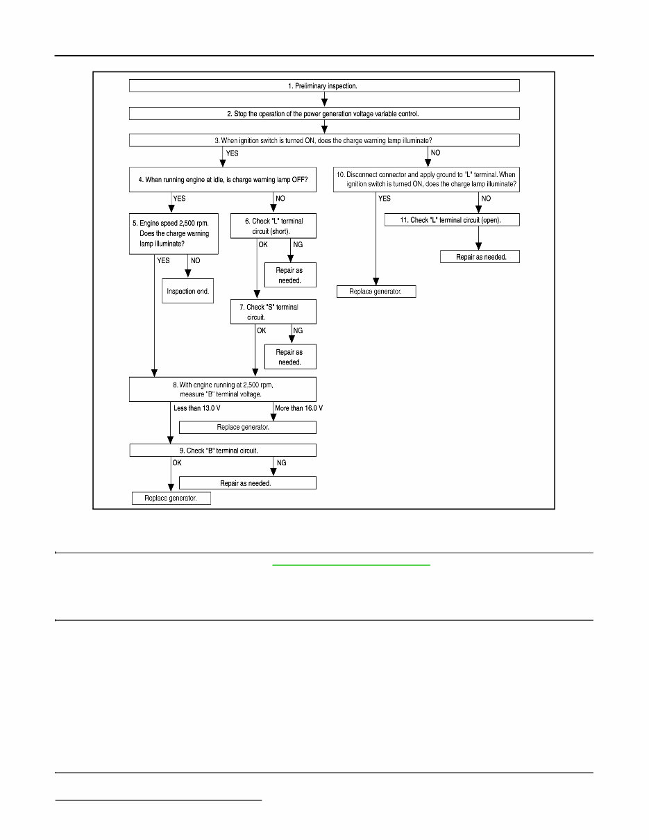
CHG-6 < BASIC INSPECTION > DIAGNOSIS AND REPAIR WORKFLOW • Use fully charged battery. DETAILED FLOW 1.PRELIMINARY INSPECTION Perform the preliminary inspection. Refer to CHG-10, "Diagnosis Procedure" . >> GO TO 2. 2.STOP POWER GENERATION VOLTAGE VARIABLE CONTROL SYSTEM Stop the operation of the power generation voltage variable control in either of the following procedures: • After selecting “ENGINE” using CONSULT, set the DUTY value of “ALTERNATOR DUTY” to 0 % by select- ing “ALTERNATOR DUTY” with “Active Test”. Continue “Active Test” until the end of inspection. (When the DUTY value is 0 or 100 %, the normal power generation is performed according to the characteristic of the IC regulator of the generator.) • Turn the ignition switch OFF, and disconnect the battery current sensor connector. [However, DTC (P1550 - P1554) of the engine might remain. After finishing the inspection, connect the battery current sensor connec- tor and erase the self-diagnostic results history of the engine using CONSULT.] >> GO TO 3. 3.INSPECTION WITH CHARGE WARNING LAMP (IGNITION SWITCH IS TURNED ON) When ignition switch is turned ON. Does the charge warning lamp illuminate? ALMIA0577GB Revision: August 2012 2012 Maxima
CHG DIAGNOSIS AND REPAIR WORKFLOW CHG-7 < BASIC INSPECTION > C D E F G H I J K L B A O P N YES >> GO TO 4. NO >> GO TO 10. 4.INSPECTION WITH CHARGE WARNING LAMP (IDLING) Start the engine and run it at idle Does the charge warning lamp turn OFF? YES >> GO TO 5. NO >> GO TO 6. 5.INSPECTION WITH CHARGE WARNING LAMP (ENGINE AT 2,500 RPM) Increase and maintain the engine speed at 2,500 rpm. Does the charge warning lamp illuminate? YES >> GO TO 8. NO >> Inspection End. 6.“L” TERMINAL CIRCUIT (SHORT) INSPECTION Check terminal “L” circuit for (short). Refer to CHG-16, "Diagnosis Procedure" . Is the inspection result normal? YES >> GO TO 7. NO >> Repair as needed. 7.“S” TERMINAL CIRCUIT INSPECTION Check terminal “S” circuit. Refer to CHG-17, "Diagnosis Procedure" . Is the inspection result normal? YES >> GO TO 8. NO >> Repair as needed. 8.MEASURE “B” TERMINAL VOLTAGE Start engine. With engine running at 2,500 rpm, measure “B” terminal voltage. What voltage does the measurement result show? Less than 13.0 V>>GO TO 9. More than 16.0 V>>Replace generator. Refer to CHG-28, "Removal and Installation" . 9.“B” TERMINAL CIRCUIT INSPECTION Check “B” terminal circuit. Refer to CHG-13, "Diagnosis Procedure" . Is the inspection result normal? YES >> Replace generator. Refer to CHG-28, "Removal and Installation" . NO >> Repair as needed. 10.INSPECTION WITH CHARGE WARNING LAMP (IGNITION SWITCH IS ON) 1. Disconnect generator connector and apply ground to “L” terminal. 2. Turn the ignition switch ON. Does the charge warning lamp illuminate? YES >> Replace generator. Refer to CHG-28, "Removal and Installation" . NO >> GO TO 11. 11.CHECK “L” TERMINAL CIRCUIT (OPEN) Check “L” terminal circuit (OPEN). Refer to CHG-14, "Diagnosis Procedure" . >> Repair as needed. Revision: August 2012 2012 Maxima
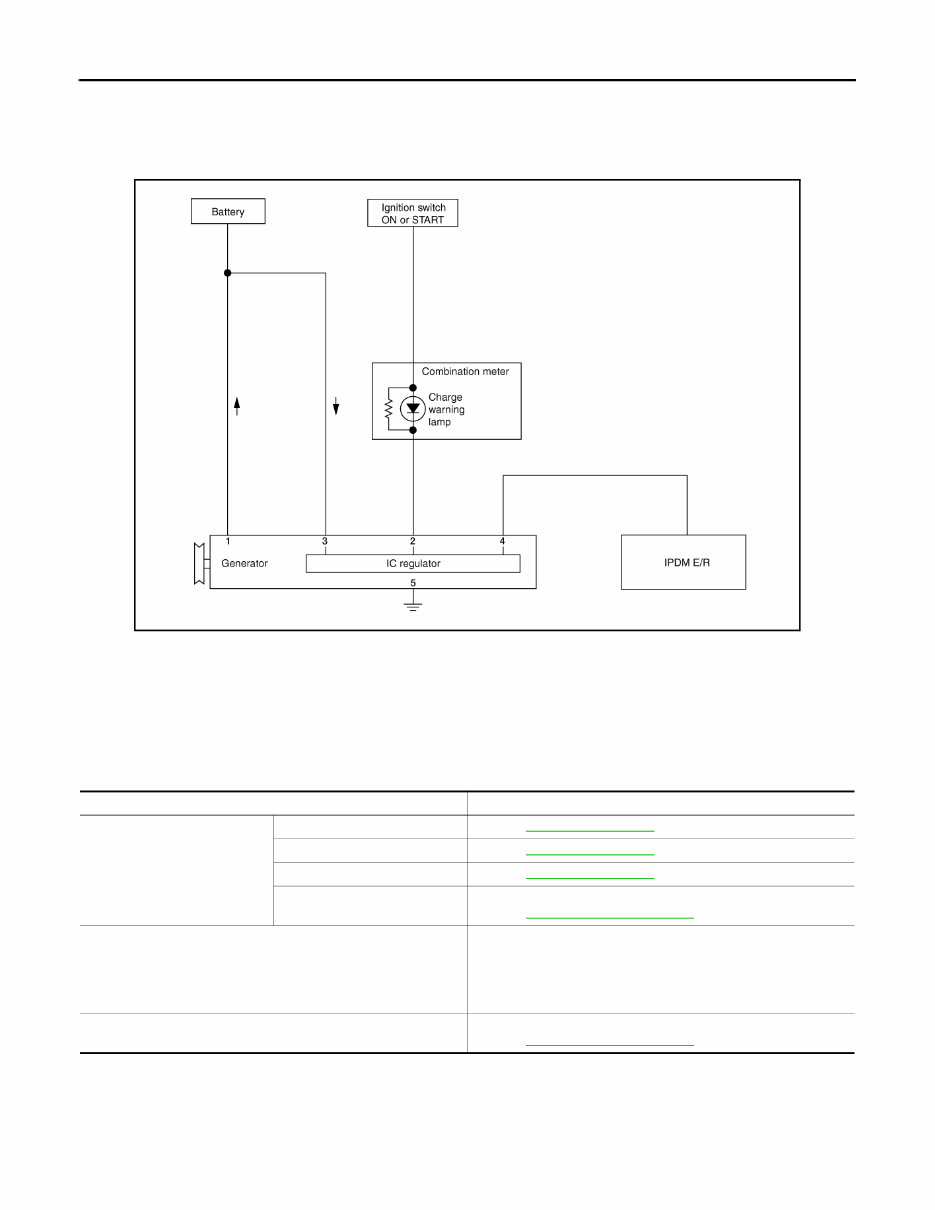
CHG-8 < SYSTEM DESCRIPTION > CHARGING SYSTEM SYSTEM DESCRIPTION CHARGING SYSTEM System Diagram INFOID:0000000007252819 System Description INFOID:0000000007252820 The generator provides DC voltage to operate the vehicle's electrical system and to keep the battery charged. The voltage output is controlled by the IC regulator. Component Description INFOID:0000000007252821 ALMIA0207GB Component part Description Generator Terminal “1” Refer to CHG-13, "Description" . Terminal “2” Refer to CHG-14, "Description" . Terminal “3” Refer to CHG-17, "Description" . Terminal “4” Used for the power generation voltage variable control system. Refer to CHG-9, "System Description" . Combination meter (Charge warning lamp) The IC regulator warning function activates to illuminate the charge warning lamp if any of the following symptoms occur while generator is operating: • Excessive voltage is produced. • No voltage is produced. IPDM E/R Used for the power generation voltage variable control system. Refer to CHG-9, "System Description" . Revision: August 2012 2012 Maxima
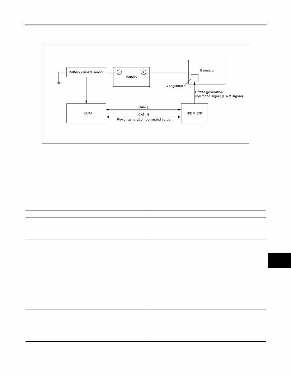
CHG POWER GENERATION VOLTAGE VARIABLE CONTROL SYSTEM CHG-9 < SYSTEM DESCRIPTION > C D E F G H I J K L B A O P N POWER GENERATION VOLTAGE VARIABLE CONTROL SYSTEM System Diagram INFOID:0000000007252822 System Description INFOID:0000000007252823 Power generation variable voltage control system has been adopted. By varying the voltage to the generator, engine load due to power generation of the generator is reduced and fuel consumption is decreased. NOTE: When any malfunction is detected in the power generation variable voltage control system, power generation is performed according to the characteristic of the IC regulator in the generator. Component Description INFOID:0000000007252824 ALMIA0057GB Component part Description Battery current sensor The battery current sensor is installed on the battery cable at the negative terminal. The battery current sensor detects the charg- ing/discharging current of the battery and sends a voltage signal to the ECM according to the current value detected. ECM The battery current sensor detects the charging/discharging cur- rent of the battery. The ECM judges the battery condition based on this signal. The ECM judges whether to request more output via the power generation voltage variable control according to the battery condi- tion. When performing the power generation voltage variable control, the ECM calculates the target power generation voltage according to the battery condition and sends the calculated value as the pow- er generation command value to the IPDM E/R. IPDM E/R The IPDM E/R converts the received power generation command value into a pulse width modulated (PWM) command signal and sends it to the IC regulator. Generator (IC regulator) The IC regulator controls the power generation voltage by the tar- get power generation voltage based on the received PWM com- mand signal. When there is no PWM command signal, the generator performs the normal power generation according to the characteristic of the IC regulator. Revision: August 2012 2012 Maxima
CHG-10 < DTC/CIRCUIT DIAGNOSIS > CHARGING SYSTEM PRELIMINARY INSPECTION DTC/CIRCUIT DIAGNOSIS CHARGING SYSTEM PRELIMINARY INSPECTION Diagnosis Procedure INFOID:0000000007252825 1.CHECK BATTERY TERMINALS CONNECTION Check if battery terminals are clean and tight. Is the inspection result normal? YES >> GO TO 2 NO >> Repair battery terminals connection. Confirm repair by performing complete Charging system test using EXP-800 NI or GR8-1200 NI (if available). Refer to applicable Instruction Manual for proper testing procedures. 2.CHECK FUSE Check for blown fuse and fusible link. Is the inspection result normal? YES >> GO TO 3 NO >> Be sure to eliminate cause of malfunction before installing new fuse or fusible link. 3.CHECK GENERATOR GROUND TERMINAL CONNECTION Check if connector E230 terminal 5 (generator ground harness) is clean and tight. Is the inspection result normal? YES >> GO TO 4 NO >> Repair connection. 4.CHECK DRIVE BELT TENSION Check drive belt tension. Refer to CHG-29, "Inspection" . Is the inspection result normal? YES >> Inspection End. NO >> Repair as needed. Unit Power source (Power supply terminals) Fuse or Fusible Link Generator Battery (terminal 3) Fuse 29 Battery (terminal 1) Fusible Link A Combination meter Ignition switch ON (terminal 2) Fuse 4 Revision: August 2012 2012 Maxima
If you are in need of a repair manual for your 2012 Nissan Maxima, look no further. Our accessible repair manual is a cost-effective and convenient alternative to traditional paper manuals. Whether you are a professional mechanic or a DIY enthusiast, this manual covers all the essential service and repair information for the Nissan Maxima.
Gone are the days of purchasing expensive traditional service manuals in book format. Our digital manual provides the same valuable information at a fraction of the cost, making it easier and more affordable to access the necessary details for maintaining and repairing your vehicle.
Whether you are tackling brake repairs, suspension component replacements, engine troubleshooting, or standard maintenance tasks, this repair manual is an invaluable resource. It contains comprehensive information on brakes, engine, suspension, steering, drivetrain, electrical systems, heating, air conditioning, and more, enabling you to address any issue with confidence.
By utilizing this repair manual , you can save a significant amount of money on vehicle maintenance and repairs. Professional mechanics often charge high fees for their services, but with this manual, you have the guidance you need to work on your own vehicle and achieve substantial cost savings.
Our repair manual is designed for ease of use and compatibility with Windows, Mac computers, smartphones, and tablets, ensuring that you can access the manual anytime and anywhere.