2011 Nissan Maxima Service & Repair Manual Software
What's Included?
Lifetime Access
Fast Download Speeds
Offline Viewing
Access Contents & Bookmarks
Full Search Facility
Print one or all pages of your manual
CHG CHG-1 ELECTRICAL & POWER CONTROL C D E F G H I J K L B SECTION CHG A O P N CONTENTS CHARGING SYSTEM BASIC INSPECTION ................................... 2 DIAGNOSIS AND REPAIR WORKFLOW ......... 2 Work Flow ................................................................ 2 SYSTEM DESCRIPTION ............................. 3 CHARGING SYSTEM ......................................... 3 System Diagram ....................................................... 3 System Description .................................................. 3 Component Description ........................................... 3 POWER GENERATION VOLTAGE VARI- ABLE CONTROL SYSTEM ................................ 4 System Diagram ....................................................... 4 System Description .................................................. 4 Component Description ............................................ 4 DTC/CIRCUIT DIAGNOSIS ......................... 5 CHARGING SYSTEM PRELIMINARY IN- SPECTION .......................................................... 5 Inspection Procedure ............................................... 5 POWER GENERATION VOLTAGE VARI- ABLE CONTROL SYSTEM OPERATION IN- SPECTION .......................................................... 6 Inspection Procedure ............................................... 6 B TERMINAL CIRCUIT ...................................... 8 Description ............................................................... 8 Diagnosis Procedure ................................................ 8 L TERMINAL CIRCUIT ....................................... 9 Description ............................................................... 9 Diagnosis Procedure ................................................ 9 S TERMINAL CIRCUIT .....................................10 Description ............................................................. 10 Diagnosis Procedure .............................................. 10 WIRING DIAGRAM ..................................... 11 CHARGING SYSTEM ....................................... 11 Wiring Diagram .......................................................11 SYMPTOM DIAGNOSIS ............................. 18 CHARGING SYSTEM ....................................... 18 Symptom Table ......................................................18 PRECAUTION ............................................. 19 PRECAUTIONS ................................................. 19 Precaution for Supplemental Restraint System (SRS) "AIR BAG" and "SEAT BELT PRE-TEN- SIONER" ................................................................19 Precaution for Power Generation Voltage Variable Control System .......................................................19 PREPARATION .......................................... 20 PREPARATION ................................................. 20 Special Service Tool ...............................................20 Commercial Service Tool .......................................20 REMOVAL AND INSTALLATION .............. 21 GENERATOR .................................................... 21 Exploded View ........................................................21 Removal and Installation ........................................21 Inspection ...............................................................22 SERVICE DATA AND SPECIFICATIONS (SDS) ........................................................... 23 SERVICE DATA AND SPECIFICATIONS (SDS) ................................................................. 23 Generator ...............................................................23 Revision: January 2012 2011 Maxima
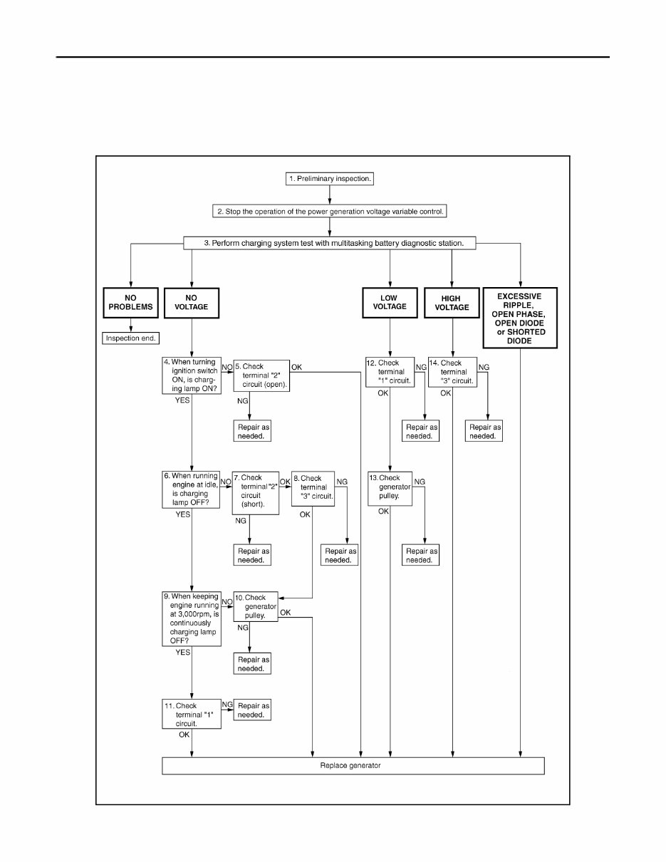
CHG-2 < BASIC INSPECTION > DIAGNOSIS AND REPAIR WORKFLOW BASIC INSPECTION DIAGNOSIS AND REPAIR WORKFLOW Work Flow INFOID:0000000006234479 OVERALL SEQUENCE AWMIA1142GB Revision: January 2012 2011 Maxima
CHG CHARGING SYSTEM CHG-3 < SYSTEM DESCRIPTION > C D E F G H I J K L B A O P N SYSTEM DESCRIPTION CHARGING SYSTEM System Diagram INFOID:0000000006234480 System Description INFOID:0000000006234481 The generator provides DC voltage to operate the vehicle's electrical system and to keep the battery charged. The voltage output is controlled by the IC regulator. Component Description INFOID:0000000006234482 ALMIA0207GB Component part Description Generator Terminal “1” Refer to CHG-8, "Description" . Terminal “2” Refer to CHG-9, "Description" . Terminal “3” Refer to CHG-10, "Description" . Terminal “4” Used for the power generation voltage variable control system. Refer to CHG-4, "System Description" . Combination meter (Charge warning lamp) The IC regulator warning function activates to illuminate the charge warning lamp if any of the following symptoms occur while generator is operating: • Excessive voltage is produced. • No voltage is produced. IPDM E/R Used for the power generation voltage variable control system. Refer to CHG-4, "System Description" . Revision: January 2012 2011 Maxima
CHG-4 < SYSTEM DESCRIPTION > POWER GENERATION VOLTAGE VARIABLE CONTROL SYSTEM POWER GENERATION VOLTAGE VARIABLE CONTROL SYSTEM System Diagram INFOID:0000000006234483 System Description INFOID:0000000006234484 Power generation variable voltage control system has been adopted. By varying the voltage to the generator, engine load due to power generation of the generator is reduced and fuel consumption is decreased. NOTE: When any malfunction is detected in the power generation variable voltage control system, power generation is performed according to the characteristic of the IC regulator in the generator. Component Description INFOID:0000000006234485 ALMIA0057GB Component part Description Battery current sensor The battery current sensor is installed on the battery cable at the negative terminal. The battery current sensor detects the charg- ing/discharging current of the battery and sends a voltage signal to the ECM according to the current value detected. ECM The battery current sensor detects the charging/discharging cur- rent of the battery. The ECM judges the battery condition based on this signal. The ECM judges whether to request more output via the power generation voltage variable control according to the battery condi- tion. When performing the power generation voltage variable control, the ECM calculates the target power generation voltage according to the battery condition and sends the calculated value as the pow- er generation command value to the IPDM E/R. IPDM E/R The IPDM E/R converts the received power generation command value into a pulse width modulated (PWM) command signal and sends it to the IC regulator. Generator (IC regulator) The IC regulator controls the power generation voltage by the tar- get power generation voltage based on the received PWM com- mand signal. When there is no PWM command signal, the generator performs the normal power generation according to the characteristic of the IC regulator. Revision: January 2012 2011 Maxima
CHG CHARGING SYSTEM PRELIMINARY INSPECTION CHG-5 < DTC/CIRCUIT DIAGNOSIS > C D E F G H I J K L B A O P N DTC/CIRCUIT DIAGNOSIS CHARGING SYSTEM PRELIMINARY INSPECTION Inspection Procedure INFOID:0000000006234486 1.CHECK BATTERY TERMINALS CONNECTION Check if battery terminals are clean and tight. Is the inspection result normal? YES >> GO TO 2 NO >> Repair battery terminals connection. 2.CHECK FUSE Check for blown fuse and fusible link. Is the inspection result normal? YES >> GO TO 3 NO >> Be sure to eliminate cause of malfunction before installing new fuse or fusible link. 3.CHECK GENERATOR GROUND TERMINAL CONNECTION Check if connector E230 terminal 5 (generator ground harness) is clean and tight. Is the inspection result normal? YES >> GO TO 4 NO >> Repair connection. 4.CHECK DRIVE BELT TENSION Check drive belt tension. Refer to CHG-22, "Inspection" . Is the inspection result normal? YES >> Inspection End. NO >> Repair as needed. Unit Power source (Power supply terminals) Fuse or Fusible Link Generator Battery (terminal 3) Fuse 29 Battery (terminal 1) Fusible Link A Combination meter Ignition switch ON (terminal 2) Fuse 4 Revision: January 2012 2011 Maxima
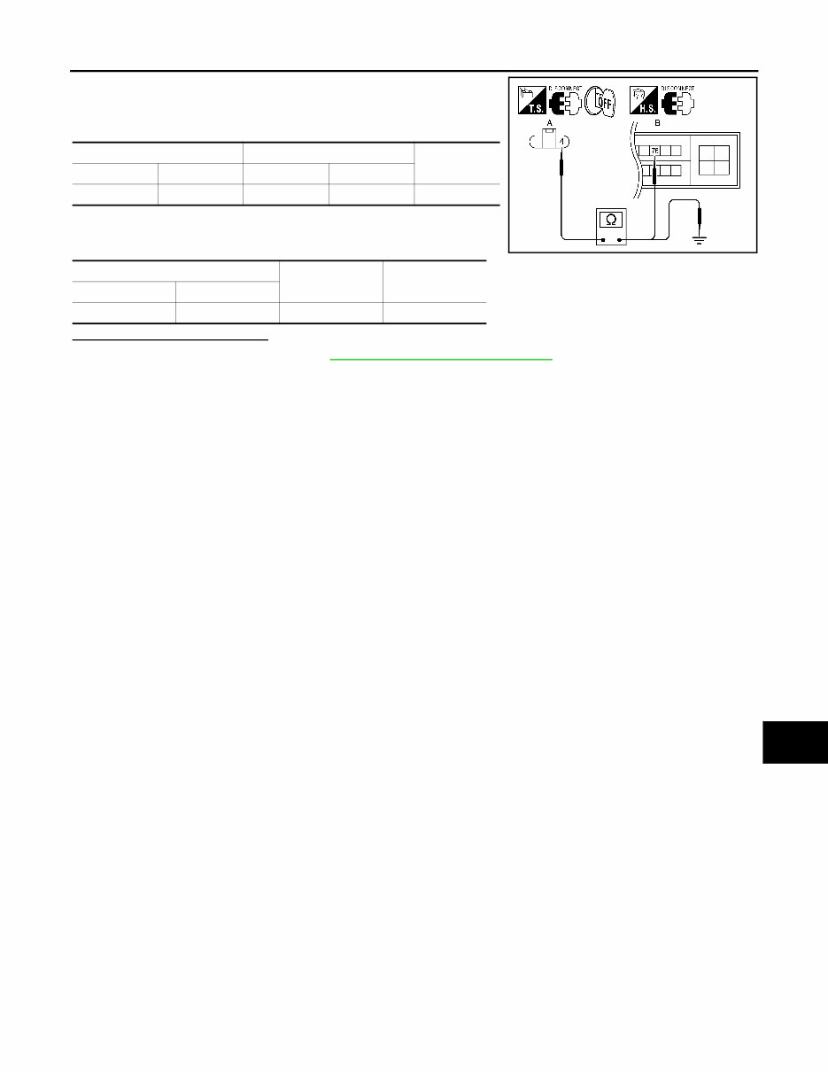
CHG-6 < DTC/CIRCUIT DIAGNOSIS > POWER GENERATION VOLTAGE VARIABLE CONTROL SYSTEM OPERATION INSPECTION POWER GENERATION VOLTAGE VARIABLE CONTROL SYSTEM OPER- ATION INSPECTION Inspection Procedure INFOID:0000000006234487 Regarding Wiring Diagram information, refer to CHG-11, "Wiring Diagram" . CAUTION: When performing this inspection, always use a charged battery that has completed the battery inspec- tion. (When the charging rate of the battery is low, the response speed of the voltage change will become slow. This can cause an incorrect inspection.) 1.CHECK ECM (CONSULT-III) Perform ECM self-diagnosis with CONSULT-III. Refer to EC-136, "CONSULT-III Function" . Self - diagnostic results content No malfunction detected>> GO TO 2 Malfunction detected>> Check applicable parts, and repair or replace corresponding parts. 2.CHECK OPERATION OF POWER GENERATION VOLTAGE VARIABLE CONTROL SYSTEM 1. Connect CONSULT-III and start the engine. 2. The selector lever is in “P” or “N” position and all of the electric loads and A/C, etc. are turned OFF. 3. Select “ALTERNATOR DUTY” in “Active Test” of “ENGINE”, and then check the value of “BATTERY VOLT” monitor when DUTY value of “ALTERNATOR DUTY” is set to 40.0 %. 4. Check the value of “BATTERY VOLT” monitor when DUTY value of “ALTERNATOR DUTY” is set to 80.0%. Is the measurement value within the specification? YES >> Inspection End. NO >> GO TO 3 3.CHECK IPDM E/R (CONSULT-III) Perform IPDM E/R self-diagnosis with CONSULT-III. Refer to PCS-13, "CONSULT - III Function (IPDM E/R)" . Self - diagnostic results content No malfunction detected>> GO TO 4 Malfunction detected>> Check applicable parts, and repair or replace corresponding parts. 4.CHECK HARNESS BETWEEN GENERATOR AND IPDM E/R 1. Turn ignition switch OFF. 2. Disconnect generator connector and IPDM E/R connector. “BATTERY VOLT” 2 seconds after setting the DUTY value of “ALTERNA- TOR DUTY” to 40.0 % : 12 - 13.6 V “BATTERY VOLT” 20 seconds after setting the DUTY value of “ALTER- NATOR DUTY” to 80.0 % : +0.5 V or more against the value of “BATTERY VOLT” monitor when DUTY value is 40.0 % Revision: January 2012 2011 Maxima
CHG POWER GENERATION VOLTAGE VARIABLE CONTROL SYSTEM OPERATION INSPECTION CHG-7 < DTC/CIRCUIT DIAGNOSIS > C D E F G H I J K L B A O P N 3. Check continuity between generator harness connector F7 (A) terminal 4 and IPDM E/R harness connector F10 (B) terminal 76. 4. Check continuity between generator harness connector F7 (A) terminal 4 and ground. Is the inspection result normal? YES >> Replace IPDM E/R. Refer to PCS-35, "Removal and Installation" . NO >> Repair harness or connector between IPDM E/R and generator. A B Continuity Connector Terminal Connector Terminal F7 4 F10 76 Yes A — Continuity Connector Terminal F7 4 Ground No ALMIA0343ZZ Revision: January 2012 2011 Maxima
CHG-8 < DTC/CIRCUIT DIAGNOSIS > B TERMINAL CIRCUIT B TERMINAL CIRCUIT Description INFOID:0000000006234488 The terminal “1” (B) circuit supplies power to charge the battery and operate the vehicle’s electrical system. Diagnosis Procedure INFOID:0000000006234489 Regarding Wiring Diagram information, refer to CHG-11, "Wiring Diagram" . 1.CHECK TERMINAL “1” CONNECTION 1. Turn ignition switch OFF. 2. Check if terminal “1” is clean and tight. Is the inspection result normal? YES >> GO TO 2 NO >> Repair terminal “1” connection. Confirm repair by performing complete Starting/Charging system test. Refer to diagnostic station instruction manual. 2.CHECK TERMINAL “1” CIRCUIT Check voltage between generator connector F6 terminal 1 and ground. Is the inspection result normal? YES >> GO TO 3 NO >> Check harness for open between generator and fusible link. 3.CHECK TERMINAL “1” CONNECTION (VOLTAGE DROP TEST) 1. Start engine, then engine running at idle and warm. 2. Check voltage between battery positive terminal and generator connector F6 terminal 1. Is the inspection result normal? YES >> Terminal “1” circuit is normal. Refer to CHG-2, "Work Flow" . NO >> Check harness between battery and generator for high resistance. 1 - ground Battery voltage ALMIA0344ZZ 1 - B+ Less than 0.2V ALMIA0345ZZ Revision: January 2012 2011 Maxima
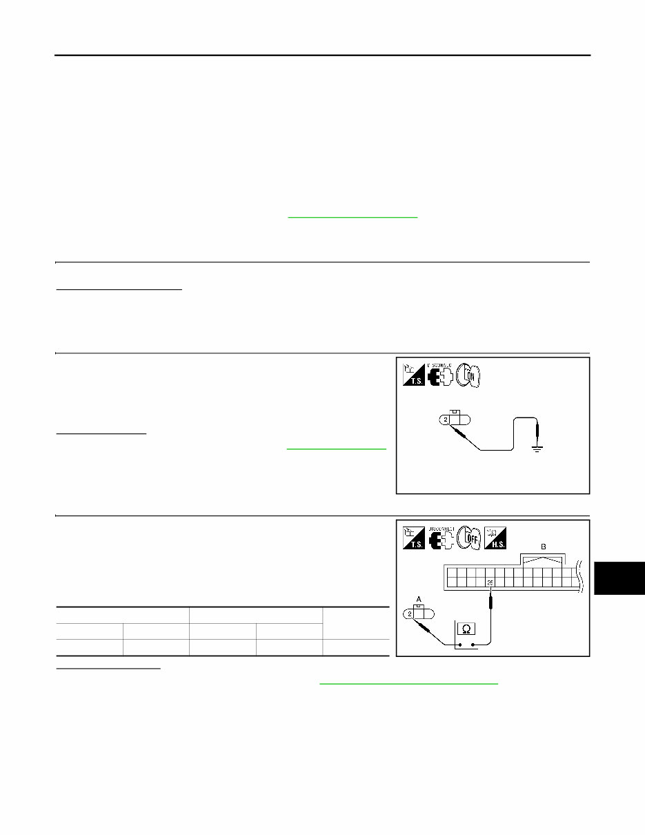
CHG L TERMINAL CIRCUIT CHG-9 < DTC/CIRCUIT DIAGNOSIS > C D E F G H I J K L B A O P N L TERMINAL CIRCUIT Description INFOID:0000000006234490 The terminal “2” (L) circuit controls the charge warning lamp. The charge warning lamp illuminates when the ignition switch is set to ON or START. When the generator is providing sufficient voltage with the engine run- ning, the charge warning lamp will go off. If the charge warning lamp illuminates with the engine running, a malfunction is indicated. Diagnosis Procedure INFOID:0000000006234491 Regarding Wiring Diagram information, refer to CHG-11, "Wiring Diagram" . 1.CHECK CHARGE WARNING LAMP CIRCUIT CONNECTION Check to see if generator connector F7 terminal 2 is clean and tight. Is the connection secure? YES >> GO TO 2 NO >> Repair the connection. Confirm repair by performing complete Starting/Charging system test. Refer to diagnostic station instruction manual. 2.CHECK CHARGE WARNING LAMP CIRCUIT 1. Disconnect generator connector F7. 2. Apply ground to generator harness connector F7 terminal 2 with the ignition switch in the ON position. Does it illuminate? YES >> Check generator function. Refer to CHG-2, "Work Flow" . NO >> GO TO 3 3.CHECK HARNESS CONTINUITY (OPEN CIRCUIT) 1. Turn ignition switch OFF. 2. Disconnect the generator connector F7. 3. Disconnect the combination meter connector M24. 4. Check continuity between generator harness connector F7 (A) terminal 2 and combination meter harness connector M24 (B) terminal 25. Is continuity present? YES >> Replace the combination meter. Refer to MWI-119, "Removal and Installation" . NO >> Repair the harness or connector. Charge lamp should illuminate ALMIA0346ZZ A B Continuity Connector Terminal Connector Terminal F7 2 M24 25 Yes AWMIA1169ZZ Revision: January 2012 2011 Maxima
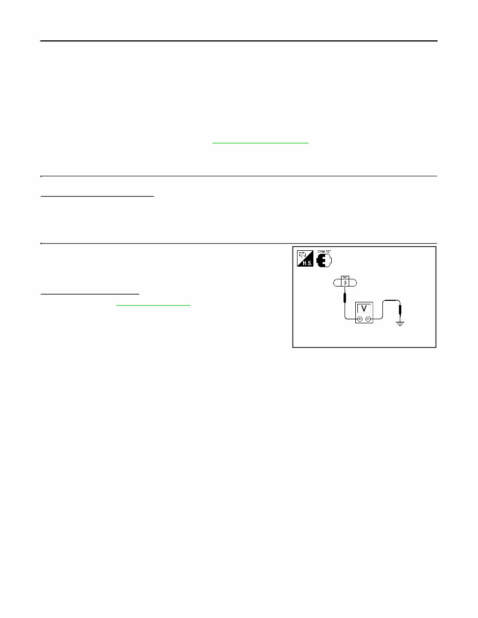
CHG-10 < DTC/CIRCUIT DIAGNOSIS > S TERMINAL CIRCUIT S TERMINAL CIRCUIT Description INFOID:0000000006234492 The output voltage of the generator is controlled by the IC regulator at terminal “3” (S) detecting the input volt- age. Terminal “3” circuit detects the battery voltage to adjust the generator output voltage with the IC regulator. Diagnosis Procedure INFOID:0000000006234493 Regarding Wiring Diagram information, refer to CHG-11, "Wiring Diagram" . 1.CHECK VOLTAGE REGULATOR CIRCUIT CONNECTION Check to see if connector F7 terminal 3 is clean and tight. Is the inspection result normal? YES >> GO TO 2 NO >> Repair terminal connection. Confirm repair by performing complete Starting/Charging system test. Refer to diagnostic station instruction manual. 2.CHECK VOLTAGE REGULATOR CIRCUIT Check voltage between generator harness connector F7 terminal 3 and ground. Does battery voltage exist? YES >> Refer to CHG-2, "Work Flow" . NO >> Check harness for open between generator and fuse. 3 - ground Battery voltage ALMIA0348ZZ Revision: January 2012 2011 Maxima
If you are in need of a repair manual for your 2011 Nissan Maxima, look no further. Our accessible repair manual software provides comprehensive coverage for the Nissan Maxima, making it an ideal resource for both professional mechanics and DIY enthusiasts.
Gone are the days of purchasing traditional service manuals in book format at a higher cost. Our repair manual software offers the same valuable information in a more affordable and convenient digital format.
Whether you require guidance for brake repairs, suspension component replacements, engine troubleshooting, or standard maintenance procedures, this repair manual software for the Nissan Maxima has you covered.
With this software, you will have access to a wealth of service information, including details on brakes, engine, suspension, steering, drivetrain, electrical systems, heating, air conditioning, and more. It equips you with the knowledge to address any automotive issue.
By utilizing this 2011 Nissan Maxima repair manual software, you can save a significant amount of money on vehicle maintenance. Take advantage of the cost-effectiveness of DIY repairs and rely on this user-friendly manual to navigate the process.
Our repair manual software is designed for easy use and is compatible with Windows, Mac computers, smartphones, and tablets, ensuring accessibility across various devices.
Recently Viewed
5,521,897Happy Clients
2,594,462eManuals
1,120,453Trusted Sellers
15Years in Business
Price:
Actual Price:
2011 Nissan Maxima Service & Repair Manual Software