

2018 Nissan LEAF Service & Repair Manual
What's Included?
Fast Download Speeds
Online & Offline Access
Access PDF Contents & Bookmarks
Full Search Facility
Print one or all pages of your manual
HOW TO USE THIS MANUAL : Repair Manual
RDE-000789996
MR —> MR sieref Link Refer to HOW TO USE THIS MANUAL : Repair Manual.
MR —> MD sieref Link Refer to Vehicle Description.
DESCRIPTION
This volume explains “Removal, Disassembly, Installation, Inspection and Adjustment” and “Trouble
Diagnosis”.
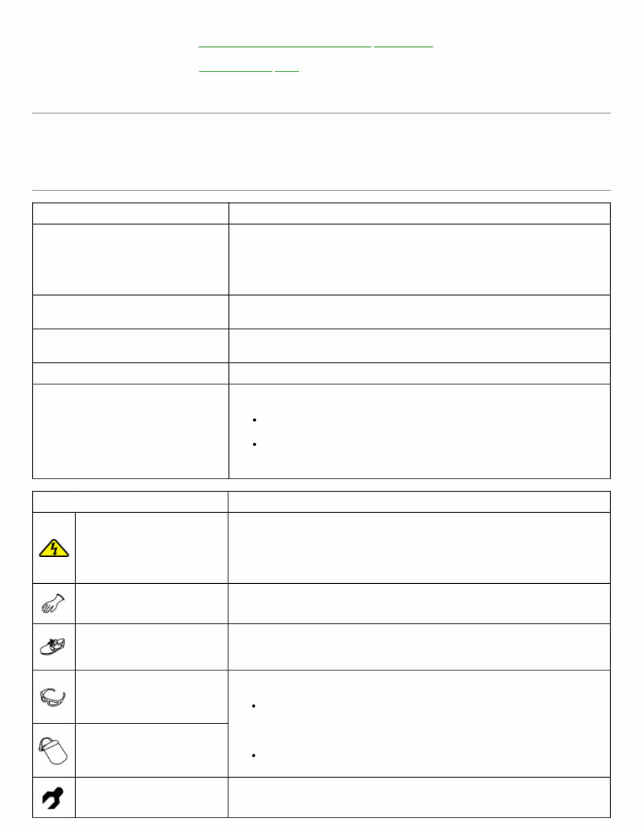
TERMS
Item Description
DANGER
To be used to inform an operation which will cause a death or serious
personal injury if instructions are not following.
Example: Touching high voltage components without using the
appropriate protective equipment will cause electrocution.
WARNING
To be used to inform an operation which may cause a death or
serious personal injury if instructions are not following.
CAUTION
To be used to inform an operation which may cause personal injury or
component damage if instructions are not following.
NOTE To be used to inform you helpful information.
BOLD STATEMENTS except
DANGER, WARNING and NOTE
Give you helpful information.
Standard value: Tolerance at inspection and adjustment.
Limit value: The maximum or minimum limit value that should
not be exceeded at inspection and adjustment.
Symbol Description
Electric shock symbol
It may cause an electric shock if instructions are not following to be
used in caution for an operation.
To be used to describe the removal of component, connector, etc.
where high voltage is/might be present.
Insulated gloves
Always wear when inspecting or performing service operation of high
voltage components.
Insulated safety
shoes/Insulated rubber
sheet
Always wear when inspecting or performing service operation of high
voltage components on lift-up vehicle.
Safety glasses
Always wear during under the circumstances
During removal/installation or check operation of high voltage
terminals and harnessed where spark might terminal appear by
short circuit.
Operation inside battery pack.
Face shield
Insulated hand tools
Always use when performing high voltage presents operation such as
operation inside high voltage battery pack.
UNITS
The UNITS given in this manual are primarily expressed as the SI UNIT (International System of
Unit), and alternatively expressed in the metric system and in the yard/pound system.
Also with regard to tightening torque of bolts and nuts, there are descriptions both about range and
about the standard tightening torque.
“Example”
Range
Outer Socket Lock Nut : 59 - 78 N·m (6.0 - 8.0 kg-m, 43 - 58 ft-lb)
Standard
Drive Shaft Installation Bolt : 44.3 N·m (4.5 kg-m, 33 ft-lb)
CONTENTS
THE CONTENTS are listed on the first page of each section.
THE TITLE is indicated on the upper portion of each page and shows the part or system.
THE PAGE NUMBER of each section consists of two or three letters which designate the particular
section and a number (e.g. “BR-5”).
THE SMALL ILLUSTRATIONS show the important steps such as inspection, use of special tools,
knacks of work and hidden or tricky steps which are not shown in the previous large illustrations.
Assembly, inspection and adjustment procedures for the complicated units such as the automatic
transaxle or transmission, etc. are presented in a step-by-step format where necessary.
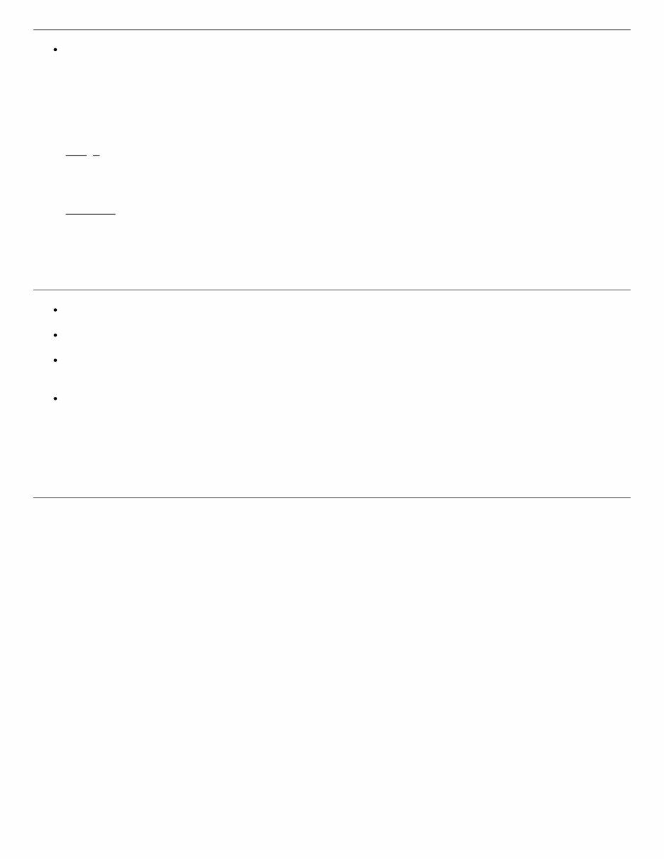
RELATION BETWEEN ILLUSTRATIONS AND DESCRIPTION
The following sample explains the relationship between the part description in an illustration, the part name
in the text and the service procedures.
RDE-000789996-01-AIA0519E
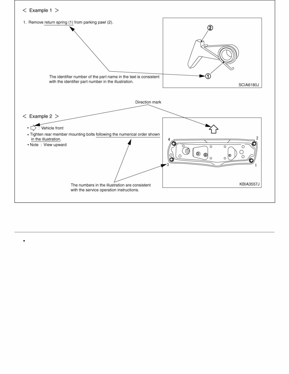
COMPONENTS
THE LARGE ILLUSTRATIONS are exploded views (see the following) and contain tightening torques,
lubrication points, section number of the PARTS CATALOG (e.g. SEC. 440) and other information
necessary to perform repairs.
The illustrations should be used in reference to service matters only. When ordering parts, refer to the
appropriate PARTS CATALOG.
Components shown in an illustration may be identified by a circled number. When this style of
illustration is used, the text description of the components will follow the illustration.
RDE-000789996-02-PFIA0511GB
1. Cap 2. Bleeder valve 3. Cylinder body
4. Piston seal 5. Piston 6. Piston boot
7. Sliding pin 8. Sliding pin boot 9. Bushing
10. Torque member
: Apply rubber grease.
: Apply brake fluid.
: N·m (kg-m, in-lb)
: Always replace after every disassembly
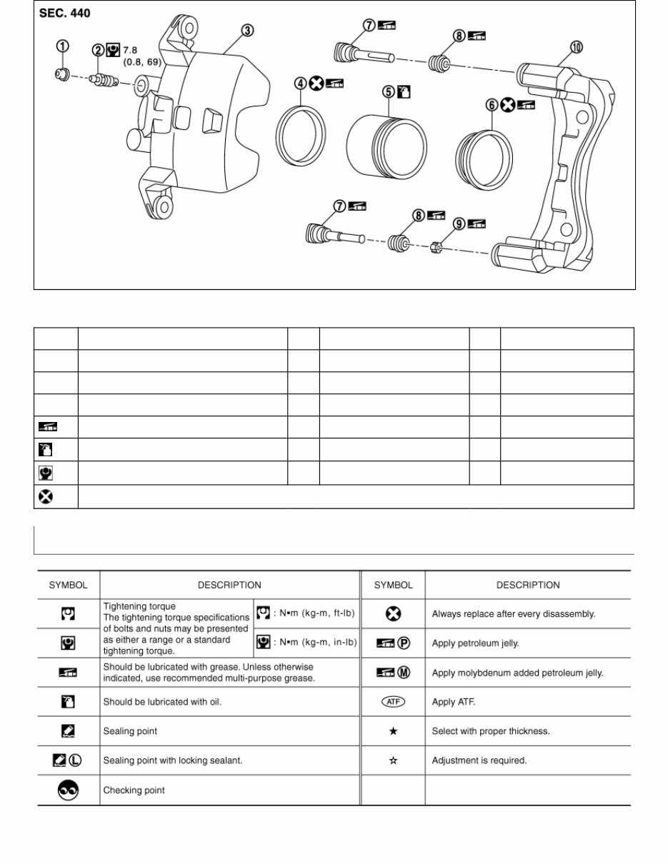
Symbols
RDE-000789996-03-AIA0749E
HOW TO USE THIS MANUAL : Diagnosis Manual
RDE-000789997
DESCRIPTION
NOTE:
Trouble diagnoses indicate work procedures required to diagnose problems effectively.
Observe the following instructions before diagnosing.
Before performing trouble diagnoses, read the “Work Flow” in each section.
After repairs, re-check that the problem has been completely eliminated.
Refer to Component Parts and Harness Connector Location for the Systems described in each section
for identification/location of components and harness connectors.
When checking circuit continuity, ignition switch should be OFF.
Refer to the Circuit Diagram for quick pinpoint check.
If you need to check circuit continuity between harness connectors in more detail, such as when a
sub-harness is used, refer to Wiring Diagram in each individual section and Harness Layout in PG
section for identification of harness connectors.
Before checking voltage at connectors, check battery voltage.
After accomplishing the Diagnosis Procedures and Electrical Components Inspection, check that all
harness connectors are reconnected as they were.
HOW TO FOLLOW TEST GROUPS IN TROUBLE DIAGNOSIS
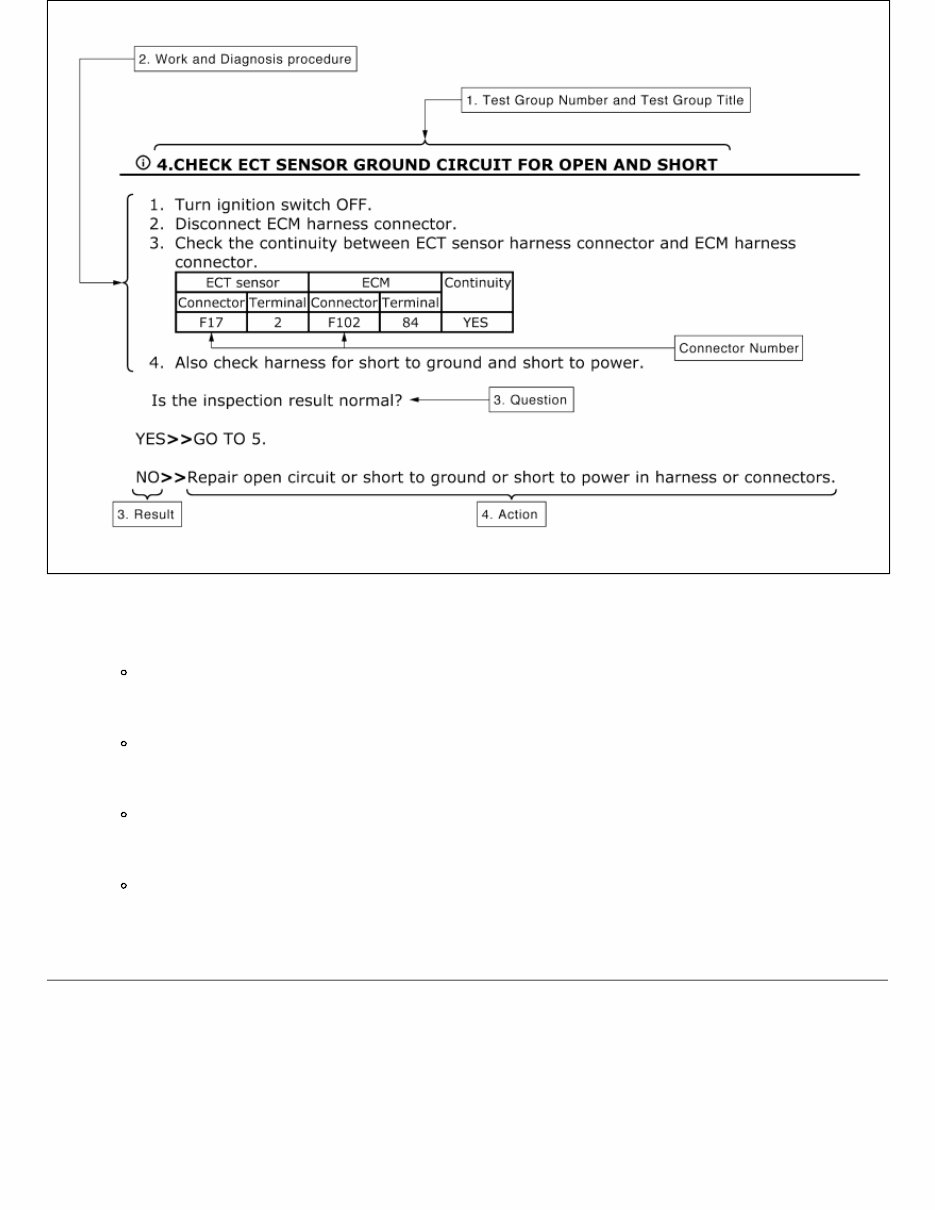
RDE-000789997-01-AIA0017GB
1. Test group number and test group title
Test group number and test group title are shown in the upper portion of each test group.
2. Work and diagnosis procedure
Start to diagnose a problem using procedures indicated in enclosed test groups.
3. Questions and results
Questions and required results are indicated in test group.
4. Action
Next action for each test group is indicated based on result of each question.
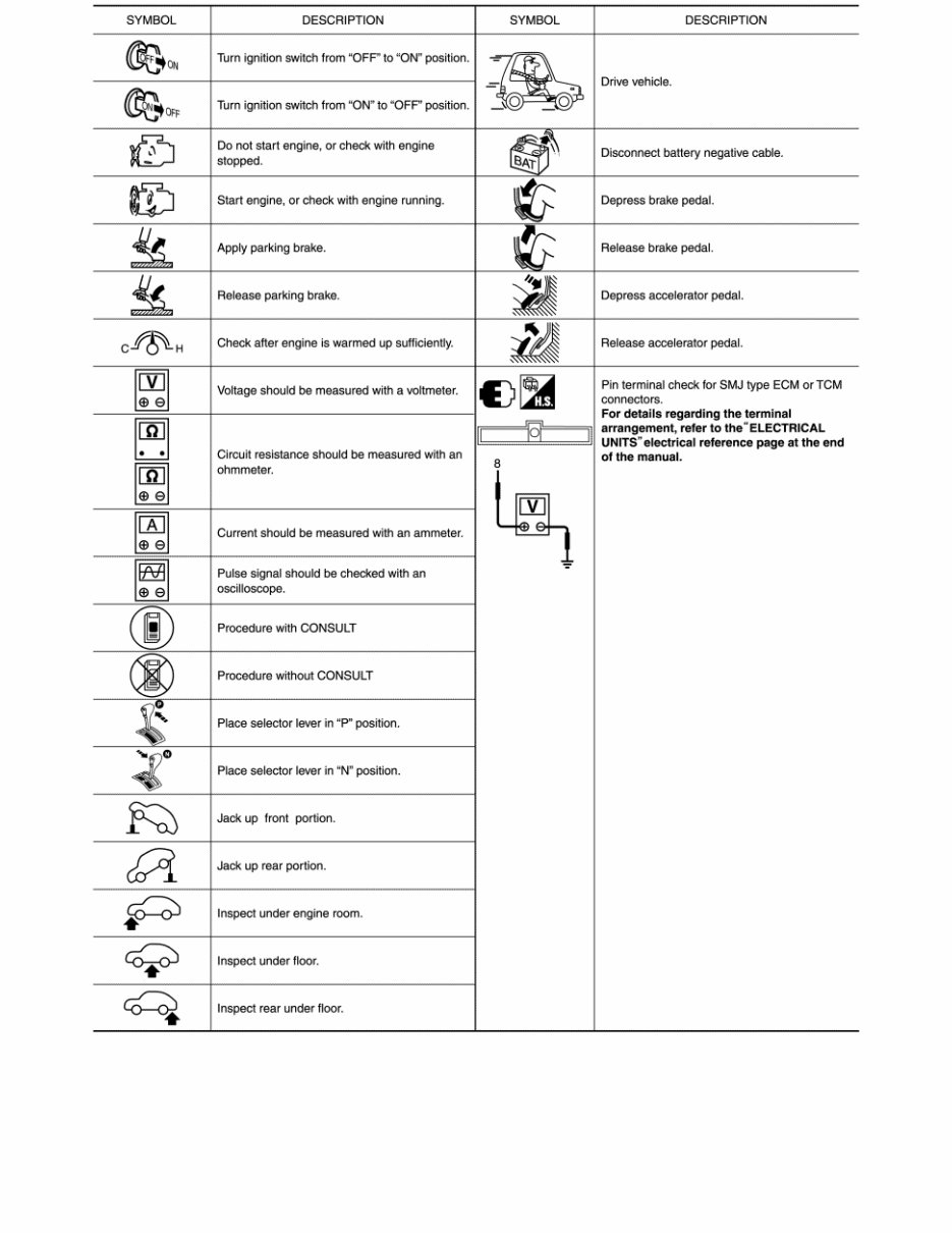
KEY TO SYMBOLS SIGNIFYING MEAAUREMENTS OR
PROCEDURES
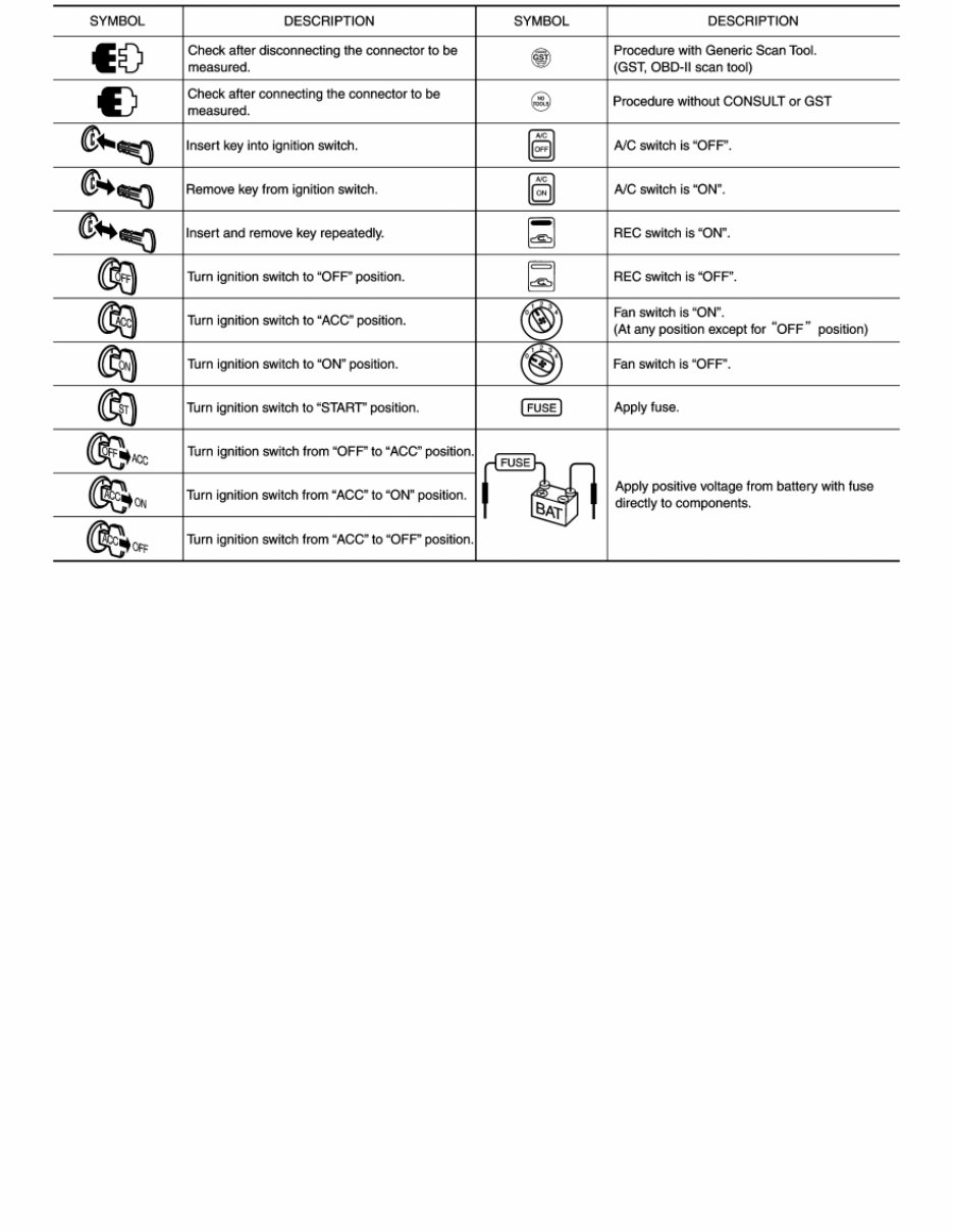
RDE-000789997-02-PAIA0982GB
RDE-000789997-03-SAIA1461GB
HOW TO USE THIS MANUAL : Wiring Diagram
RDE-000789998
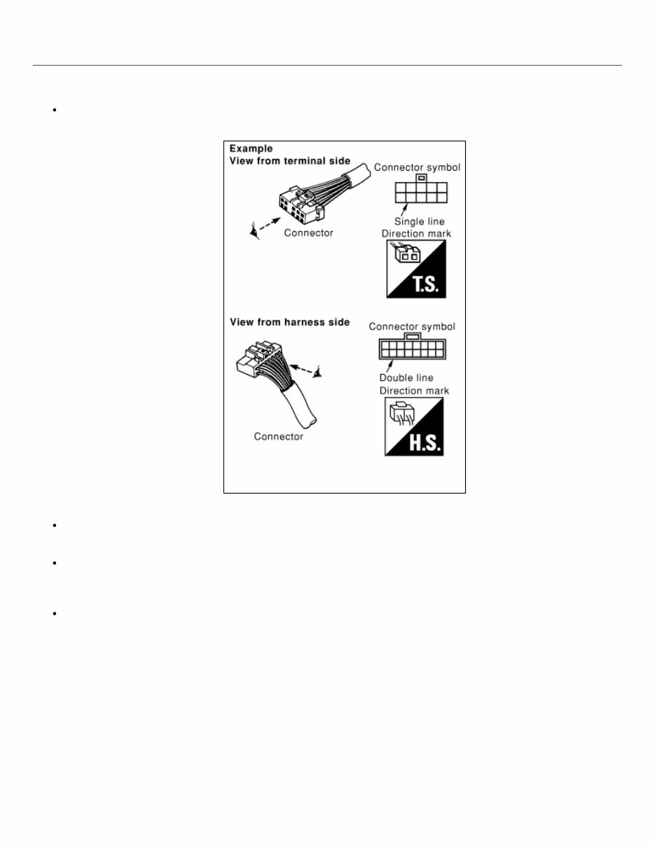
CONNECTOR SYMBOLS
Most of connector symbols in wiring diagrams are shown from the terminal side.
Connector symbols shown from the terminal side are enclosed by a single line and followed by the
direction mark.
RDE-000789998-03-AIA0257E
Connector symbols shown from the harness side are enclosed by a double line and followed by the
direction mark.
Certain systems and components, especially those related to OBD, may use a new style slide-locking
type harness connector. For description and how to disconnect, refer to PG section, “Description”,
“HARNESS CONNECTOR”.
Male and female terminals
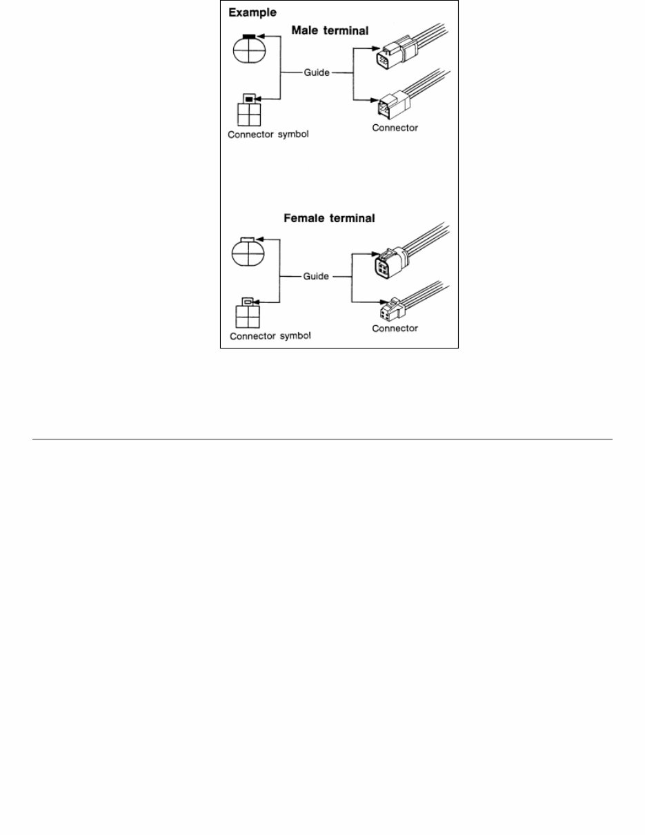
RDE-000789998-04-GI363
Connector guides for male terminals are shown in black and female terminals in white in wiring
diagrams.
SAMPLE/WIRING DIAGRAM -EXAMPLE-
Each section includes wiring diagrams.
You're Reading a Preview
What's Included?
Fast Download Speeds
Online & Offline Access
Access PDF Contents & Bookmarks
Full Search Facility
Print one or all pages of your manual
$87.99
Viewed 36 Times Today


Secure transaction
What's Included?
Fast Download Speeds
Online & Offline Access
Access PDF Contents & Bookmarks
Full Search Facility
Print one or all pages of your manual
$87.99
The 2018 Nissan LEAF Service & Repair Manual is an essential tool for any DIY car owner. This comprehensive repair manual contains all the troubleshooting and replacement procedures provided by the manufacturer, making it easy to fix any problems with your vehicle.
With step-by-step instructions, clear images, and exploded-view illustrations, this manual is user-friendly and suitable for both novice and experienced mechanics. It covers a range of models and can be accessed on any electronic device, including PC and Mac computers, Android and Apple smartphones and tablets, making it convenient to carry around and refer to whenever needed.
Regular maintenance is crucial for the durability of your vehicle, and this manual provides the manufacturer's recommended troubleshooting charts and replacement procedures to help keep your car in top condition. By following these instructions, you can save on repairs, increase your vehicle's reliability, and avoid frequent trips to the repair shop.
No more flipping through hundreds of pages to find specific information or dealing with greasy, torn, or lost pages. This manual is easily searchable, and you can take screenshots, bookmark pages, and print out specific sections if desired.
Don't let car troubles slow you down. Get the 2018 Nissan LEAF Service & Repair Manual and confidently handle any repairs your vehicle may need.


