ACC-1 ELECTRIC POWER TRAIN D E F G H I J K L M SECTION ACC A B ACC N O P CONTENTS ACCELERATOR CONTROL SYSTEM PRECAUTION .............................................. 2 PRECAUTIONS .................................................. 2 Precaution for Technicians Using Medical Electric ...... 2 Point to Be Checked Before Starting Maintenance Work ......................................................................... 2 Precaution for Supplemental Restraint System (SRS) "AIR BAG" and "SEAT BELT PRE-TEN- SIONER" .................................................................. 2 REMOVAL AND INSTALLATION ............... 4 ACCELERATOR CONTROL SYSTEM .............. 4 Exploded View ......................................................... 4 Removal and Installation ......................................... 4 Inspection ................................................................ 5 SERVICE DATA AND SPECIFICATIONS (SDS) ............................................................ 6 SERVICE DATA AND SPECIFICATIONS (SDS) .................................................................. 6 Accelerator Control .................................................. 6 Revision: August 2015 2016 LEAF NAM
ACC-2 < PRECAUTION > PRECAUTIONS PRECAUTION PRECAUTIONS Precaution for Technicians Using Medical Electric INFOID:0000000012420214 OPERATION PROHIBITION WARNING: • Parts with strong magnet is used in this vehicle. • Technicians using a medical electric device such as pacemaker must never perform operation on the vehicle, as magnetic field can affect the device function by approaching to such parts. NORMAL CHARGE PRECAUTION WARNING: • If a technician uses a medical electric device such as an implantable cardiac pacemaker or an implantable cardioverter defibrillator, the possible effects on the devices must be checked with the device manufacturer before starting the charge operation. • As radiated electromagnetic wave generated by PDM (Power Delivery Module) at normal charge operation may affect medical electric devices, a technician using a medical electric device such as implantable cardiac pacemaker or an implantable cardioverter defibrillator must not approach motor room [PDM (Power Delivery Module)] at the hood-opened condition during normal charge operation. PRECAUTION AT TELEMATICS SYSTEM OPERATION WARNING: • If a technician uses implantable cardiac pacemaker or implantable cardioverter defibrillator (ICD), avoid the device implanted part from approaching within approximately 220 mm (8.66 in) from inte- rior/exterior antenna. • The electromagnetic wave of TCU might affect the function of the implantable cardiac pacemaker or the implantable cardioverter defibrillator (ICD), when using the service, etc. • If a technician uses other medical electric devices than implantable cardiac pacemaker or implant- able cardioverter defibrillator (ICD), the electromagnetic wave of TCU might affect the function of the device. The possible effects on the devices must be checked with the device manufacturer before TCU use. PRECAUTION AT INTELLIGENT KEY SYSTEM OPERATION WARNING: • If a technician uses implantable cardiac pacemaker or implantable cardioverter defibrillator (ICD), avoid the device implanted part from approaching within approximately 220 mm (8.66 in) from inte- rior/exterior antenna. • The electromagnetic wave of Intelligent Key might affect the function of the implantable cardiac pacemaker or the implantable cardioverter defibrillator (ICD), at door operation, at each request switch operation, or at engine starting. • If a technician uses other medical electric devices than implantable cardiac pacemaker or implant- able cardioverter defibrillator (ICD), the electromagnetic wave of Intelligent Key might affect the function of the device. The possible effects on the devices must be checked with the device manu- facturer before Intelligent Key use. Point to Be Checked Before Starting Maintenance Work INFOID:0000000012420215 The high voltage system may starts automatically. It is required to check that the timer air conditioner and timer charge (during EVSE connection) are not set before starting maintenance work. NOTE: If the timer air conditioner or timer charge (during EVSE connection) is set, the high voltage system starts automatically even when the power switch is in OFF state. Precaution for Supplemental Restraint System (SRS) "AIR BAG" and "SEAT BELT PRE-TENSIONER" INFOID:0000000012420216 The Supplemental Restraint System such as “AIR BAG” and “SEAT BELT PRE-TENSIONER”, used along with a front seat belt, helps to reduce the risk or severity of injury to the driver and front passenger for certain types of collision. This system includes seat belt switch inputs and dual stage front air bag modules. The SRS Revision: August 2015 2016 LEAF NAM
PRECAUTIONS ACC-3 < PRECAUTION > D E F G H I J K L M A B ACC N O P system uses the seat belt switches to determine the front air bag deployment, and may only deploy one front air bag, depending on the severity of a collision and whether the front occupants are belted or unbelted. Information necessary to service the system safely is included in the SR and SB section of this Service Man- ual. WARNING: • To avoid rendering the SRS inoperative, which could increase the risk of personal injury or death in the event of a collision which would result in air bag inflation, all maintenance must be performed by an authorized NISSAN/INFINITI dealer. • Improper maintenance, including incorrect removal and installation of the SRS, can lead to personal injury caused by unintentional activation of the system. For removal of Spiral Cable and Air Bag Module, see the SR section. • Do not use electrical test equipment on any circuit related to the SRS unless instructed to in this Service Manual. SRS wiring harnesses can be identified by yellow and/or orange harnesses or har- ness connectors. PRECAUTIONS WHEN USING POWER TOOLS (AIR OR ELECTRIC) AND HAMMERS WARNING: • When working near the Airbag Diagnosis Sensor Unit or other Airbag System sensors with the Igni- tion ON or engine running, DO NOT use air or electric power tools or strike near the sensor(s) with a hammer. Heavy vibration could activate the sensor(s) and deploy the air bag(s), possibly causing serious injury. • When using air or electric power tools or hammers, always switch the Ignition OFF, disconnect the battery and wait at least three minutes before performing any service. Revision: August 2015 2016 LEAF NAM
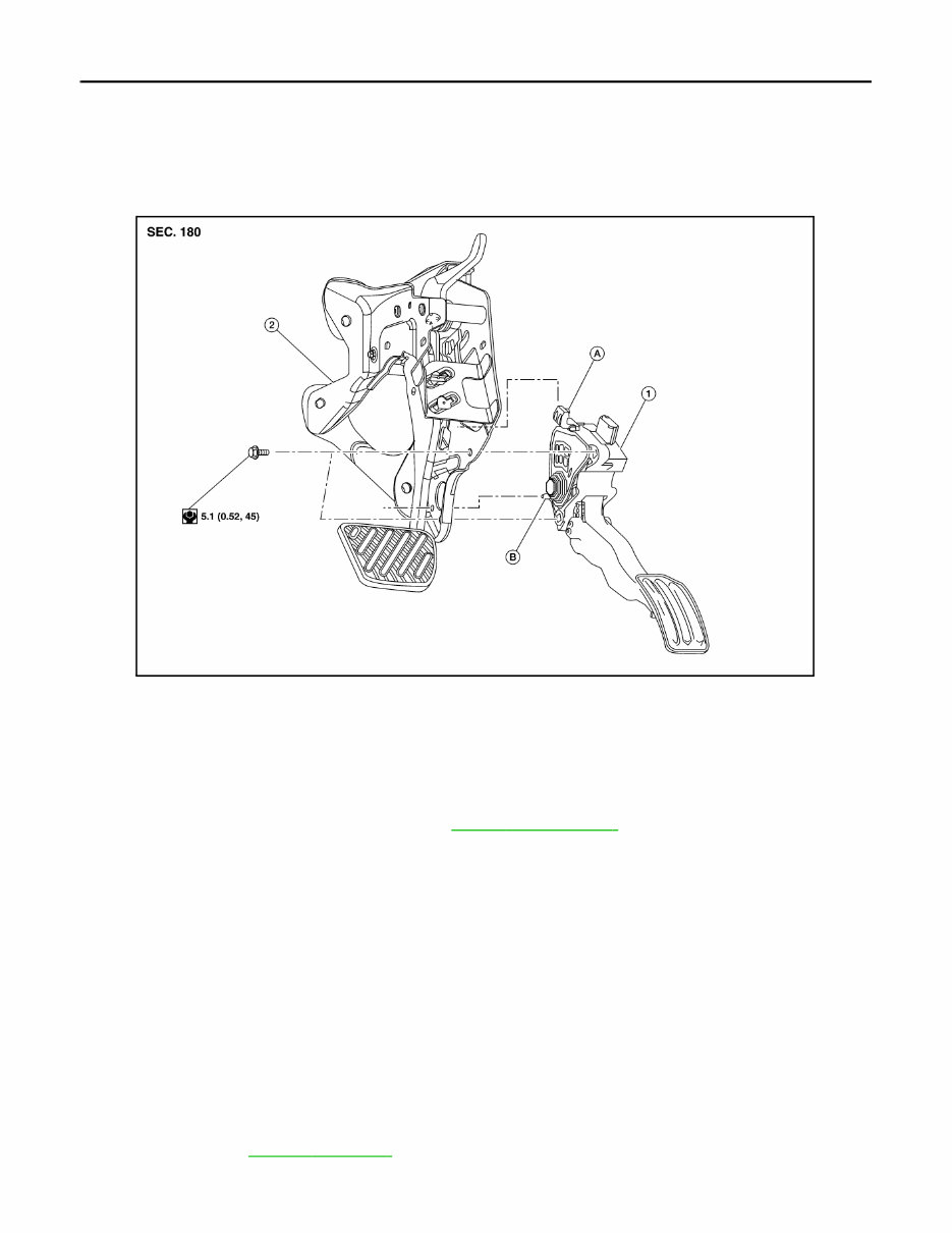
ACC-4 < REMOVAL AND INSTALLATION > ACCELERATOR CONTROL SYSTEM REMOVAL AND INSTALLATION ACCELERATOR CONTROL SYSTEM Exploded View INFOID:0000000012420217 Removal and Installation INFOID:0000000012420218 REMOVAL 1. Remove instrument under cover (LH). Refer to IP-16, " Exploded View " . 2. Disconnect the harness connector from the accelerator pedal position sensor. 3. Remove the accelerator pedal bolts and the accelerator pedal assembly. CAUTION: • Do not disassemble accelerator pedal assembly. Do not remove accelerator pedal position sen- sor from accelerator pedal assembly. • Avoid impact from dropping etc. during handling. • Be careful to keep accelerator pedal assembly away from water. INSTALLATION Installation is in the reverse order of removal. NOTE: When installing the accelerator pedal assembly, make sure to align locator hook and locator pin before install- ing bolts. CAUTION: Do not squeeze locating hook into the brake pedal bracket when inserting locating pin into the hole on the brake pedal bracket side. NOTE: For inspection, refer to ACC-5, " Inspection " . 1. Accelerator pedal assembly 2. Brake pedal bracket A. Locating hook B. Locating pin AWCIA0097ZZ Revision: August 2015 2016 LEAF NAM
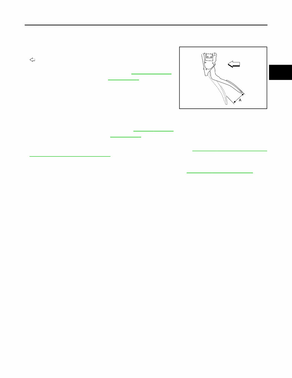
ACCELERATOR CONTROL SYSTEM ACC-5 < REMOVAL AND INSTALLATION > D E F G H I J K L M A B ACC N O P Inspection INFOID:0000000012420219 INSPECTION AFTER INSTALLATION • Check that the accelerator pedal moves smoothly within the whole operation range when it is fully depressed and released. : Front • Check the accelerator pedal height. • Check that the accelerator pedal returns to the fully released position. • For the electrical inspection of accelerator pedal position sensor. Refer to EVC-216, " Component Inspection (Accelerator Pedal Position Sensor) " . CAUTION: • Whenever the harness connector of the accelerator pedal position sensor has been disconnected, perform "Accelerator Pedal Released Position Learning". Refer to EVC-135, " Work Procedure " . • The accelerator pedal should operate smoothly without catching when the pedal operating force is released. The pedal should return smoothly to the fully raised position. The spring should be free from damage. Accelerator pedal stroke (A) : Refer to ACC-6, " Acceler- ator Control " ALBIA0798ZZ Accelerator pedal height : Refer to ACC-6, " Acceler- ator Control " Revision: August 2015 2016 LEAF NAM
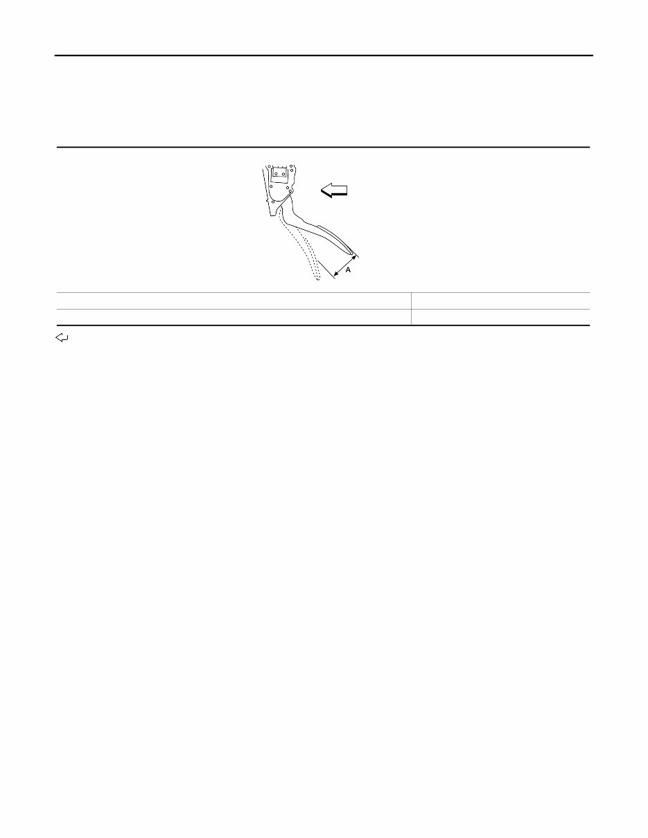
ACC-6 < SERVICE DATA AND SPECIFICATIONS (SDS) SERVICE DATA AND SPECIFICATIONS (SDS) SERVICE DATA AND SPECIFICATIONS (SDS) SERVICE DATA AND SPECIFICATIONS (SDS) Accelerator Control INFOID:0000000012420220 Unit: mm (in) : Front Accelerator pedal stroke (A) 49.8 - 52.6 (1.96 - 2.07) Accelerator pedal height 124.9 +10, -0 (4.92 +0.4, -0) ALBIA0798ZZ Revision: August 2015 2016 LEAF NAM
The 2015 Nissan LEAF Service & Repair Manual is a comprehensive guide for troubleshooting and repairing issues with your vehicle. This repair manual provides step-by-step instructions, clear images, and exploded-view illustrations, making it easy for any DIY enthusiast to fix problems on their own.
Regular maintenance is essential to keep your vehicle running smoothly, and this manual contains the manufacturer's recommended troubleshooting charts and replacement procedures. By following these guidelines, you can save on repairs, increase your vehicle's reliability, and keep your trips to the repair shop at bay.
What sets this repair manual apart is its convenience. No more flipping through hundreds of pages or dealing with greasy, torn, or lost pages. You can carry this electronic manual with you on any device, whether it's a computer, smartphone, or tablet. You can also easily search for specific information, take screenshots, and bookmark pages for future reference.
If you prefer a physical copy, you can easily print out the manual. It is compatible with any electronic device and only requires Adobe Reader, which is available for free.
Don't let vehicle problems slow you down. With the 2015 Nissan LEAF Service & Repair Manual, you have all the necessary tools to keep your vehicle in top shape without breaking the bank. Get your copy today and take control of your vehicle's maintenance needs.