Precaution for Technicians Using Medical Electric OPERATION PROHIBITION WARNING: Parts with strong magnet is used in this vehicle. Technicians using a medical electric device such as pacemaker must never perform operation on the vehicle, as magnetic field can affect the device function by approaching to such parts. NORMAL CHARGE PRECAUTION WARNING: If a technician uses a medical electric device such as an implantable cardiac pacemaker or an implantable cardioverter defibrillator, the possible effects on the devices must be checked with the device manufacturer before starting the charge operation. As radiated electromagnetic wave generated by on board charger at normal charge operation may effect medical electric devices, a technician using a medical electric device such as implantable cardiac pacemaker or an implantable cardioverter defibrillator must not enter the vehicle compartment (including luggage room) during normal charge operation. PRECAUTION AT TELEMATICS SYSTEM OPERATION WARNING: If a technician uses implantable cardiac pacemaker or implantable cardioverter defibrillator (ICD), avoid the device implanted part from approaching within approximately 220 mm (8.66 in) from interior/exterior antenna. The electromagnetic wave of TCU might affect the function of the implantable cardiac pacemaker or the implantable cardioverter defibrillator (ICD), when using the service, etc. If a technician uses other medical electric devices than implantable cardiac pacemaker or implantable cardioverter defibrillator (ICD), the electromagnetic wave of TCU might affect the function of the device. The possible effects on the devices must be checked with the device manufacturer before TCU use. PRECAUTION AT INTELLIGENT KEY SYSTEM OPERATION WARNING: If a technician uses implantable cardiac pacemaker or implantable cardioverter defibrillator (ICD), avoid the device implanted part from approaching within approximately 220 mm (8.66 in) from interior/exterior antenna. The electromagnetic wave of Intelligent Key might affect the function of the implantable cardiac pacemaker or the implantable cardioverter defibrillator (ICD), at door operation, at each request switch operation, or at engine starting. If a technician uses other medical electric devices than implantable cardiac pacemaker or implantable cardioverter defibrillator (ICD), the electromagnetic wave of Intelligent Key might affect the function of the device. The possible effects on the devices must be checked with the device manufacturer before Intelligent Key use.
Point to Be Checked Before Starting Maintenance Work The high voltage system may starts automatically. It is required to check that the timer air conditioner and timer charge (during EVSE connection) are not set before starting maintenance work. NOTE: If the timer air conditioner or timer charge (during EVSE connection) is set, the high voltage system starts automatically even when the power switch is in OFF state.
Precaution for Supplemental Restraint System (SRS) "AIR BAG" and "SEAT BELT PRE-TENSIONER" The Supplemental Restraint System such as “AIR BAG” and “SEAT BELT PRE-TENSIONER”, used along with a front seat belt, helps to reduce the risk or severity of injury to the driver and front passenger for certain types of collision. This system includes seat belt switch inputs and dual stage front air bag modules. The SRS system uses the seat belt switches to determine the front air bag deployment, and may only deploy one front air bag, depending on the severity of a collision and whether the front occupants are belted or unbelted. Information necessary to service the system safely is included in the “SRS AIR BAG” and “SEAT BELT” of this Service Manual. WARNING: Always observe the following items for preventing accidental activation. To avoid rendering the SRS inoperative, which could increase the risk of personal injury or death in the event of a collision that would result in air bag inflation, it is recommended that all maintenance and repair be performed by an authorized NISSAN/INFINITI dealer. Improper repair, including incorrect removal and installation of the SRS, can lead to personal injury caused by unintentional activation of the system. For removal of Spiral Cable and Air Bag Module, see “SRS AIR BAG”. Never use electrical test equipment on any circuit related to the SRS unless instructed to in this Service Manual. SRS wiring harnesses can be identified by yellow and/or orange harnesses or harness connectors. PRECAUTIONS WHEN USING POWER TOOLS (AIR OR ELECTRIC) AND HAMMERS WARNING: Always observe the following items for preventing accidental activation. When working near the Air Bag Diagnosis Sensor Unit or other Air Bag System sensors with the power switch ON, never use air or electric power tools or strike near the sensor(s) with a hammer. Heavy vibration could activate the sensor(s) and deploy the air bag(s), possibly causing serious injury. When using air or electric power tools or hammers, always switch the power switch OFF, disconnect the 12V battery or batteries, and wait at least 3 minutes before performing any service.
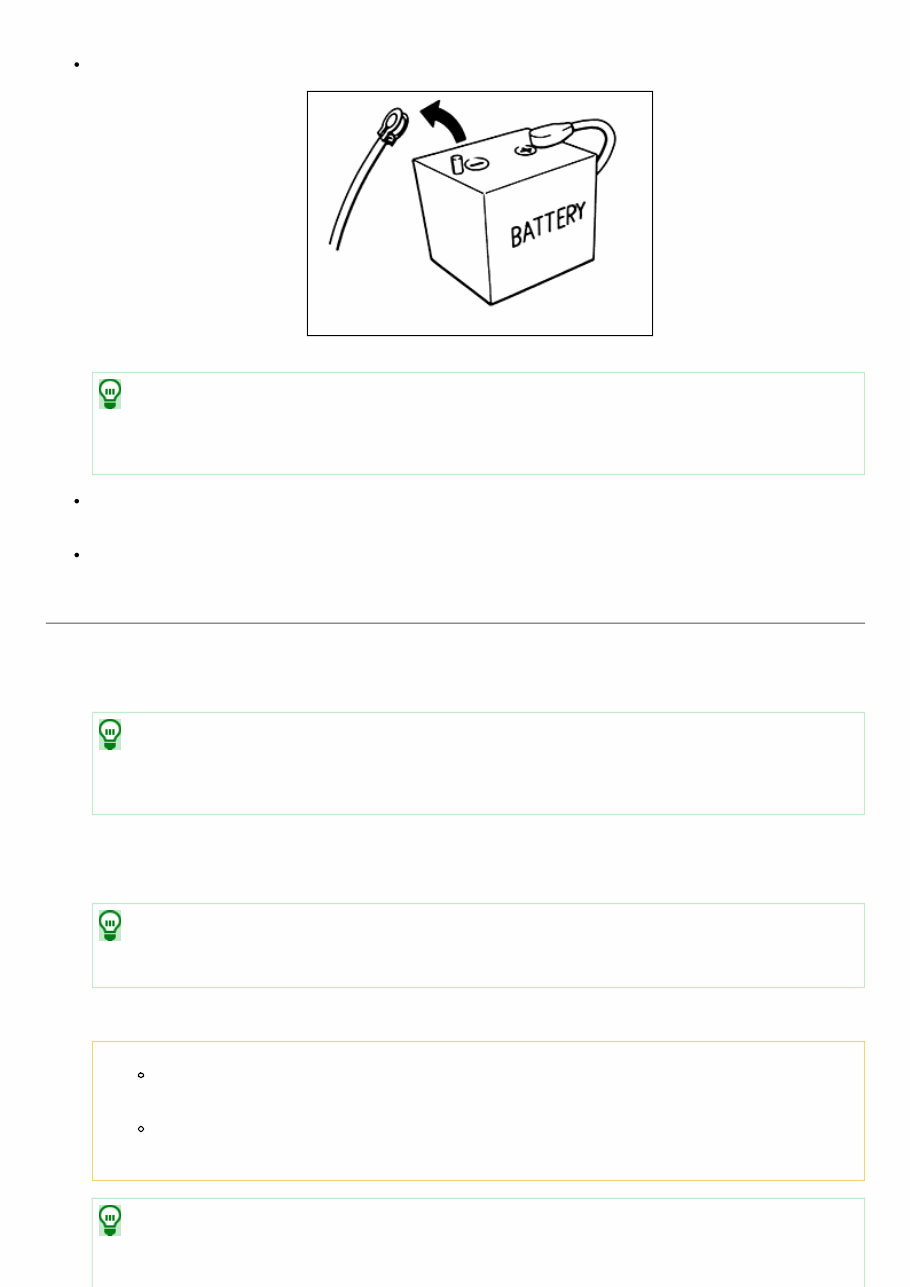
Precautions for Removing Battery Terminal When removing the 12V battery terminal, turn OFF the power switch and wait at least 5 minutes. NISSK0000000006991375-01-SEF289H NOTE: ECU may be active for several minutes after the power switch is turned OFF. If the battery terminal is removed before ECU stops, then a DTC detection error or ECU data corruption may occur. Always disconnect the battery terminal within 60 minutes after turning OFF the power switch. Even when the power switch is OFF, the 12V battery automatic charge control may automatically start after a lapse of 60 minutes from power switch OFF. Disconnect 12V battery terminal according to the following steps. WORK PROCEDURE 1. Open the hood. 2. Check that charge cable is not connected to the charge port. NOTE: If charge cable (including EVSE) is connected, the air conditioning system may be automatically activated by the timer A/C function. 3. Turn the power switch OFF → ON → OFF. Get out of the vehicle. Close all doors (including back door). 4. Check that the charge status indicator lamp does not blink and wait for 5 minutes or more. NOTE: If the battery is removed within 5 minutes after the power switch is turned OFF, plural DTCs may be detected. 5. Remove 12V battery terminal within 60 minutes after the power switch is turned OFF at Step 3. CAUTION: After all doors (including back door) are closed, if a door (including back door) is opened before battery terminals are disconnected, start over from Step 1. After turning the power switch OFF, if “Remote A/C” is activated by user operation, stop the air conditioner and start over from Step 1. NOTE:
Once the power switch is turned ON → OFF, the 12V battery automatic charge control does not start for approximately 1 hour. For vehicles with the 2-batteries, be sure to connect the main battery and the sub battery before turning ON the power switch. NOTE: If the power switch is turned ON with any one of the terminals of main battery and sub battery disconnected, then DTC may be detected. After installing the 12V battery, always check "Self Diagnosis Result" of all ECUs and erase DTC. NOTE: The removal of 12V battery may cause a DTC detection error.
Precaution for Procedure without Cowl Top Cover When performing the procedure after removing cowl top cover, cover the lower end of windshield with urethane, etc to prevent damage to windshield. NISSK0000000006991376-01-PIIB3706J
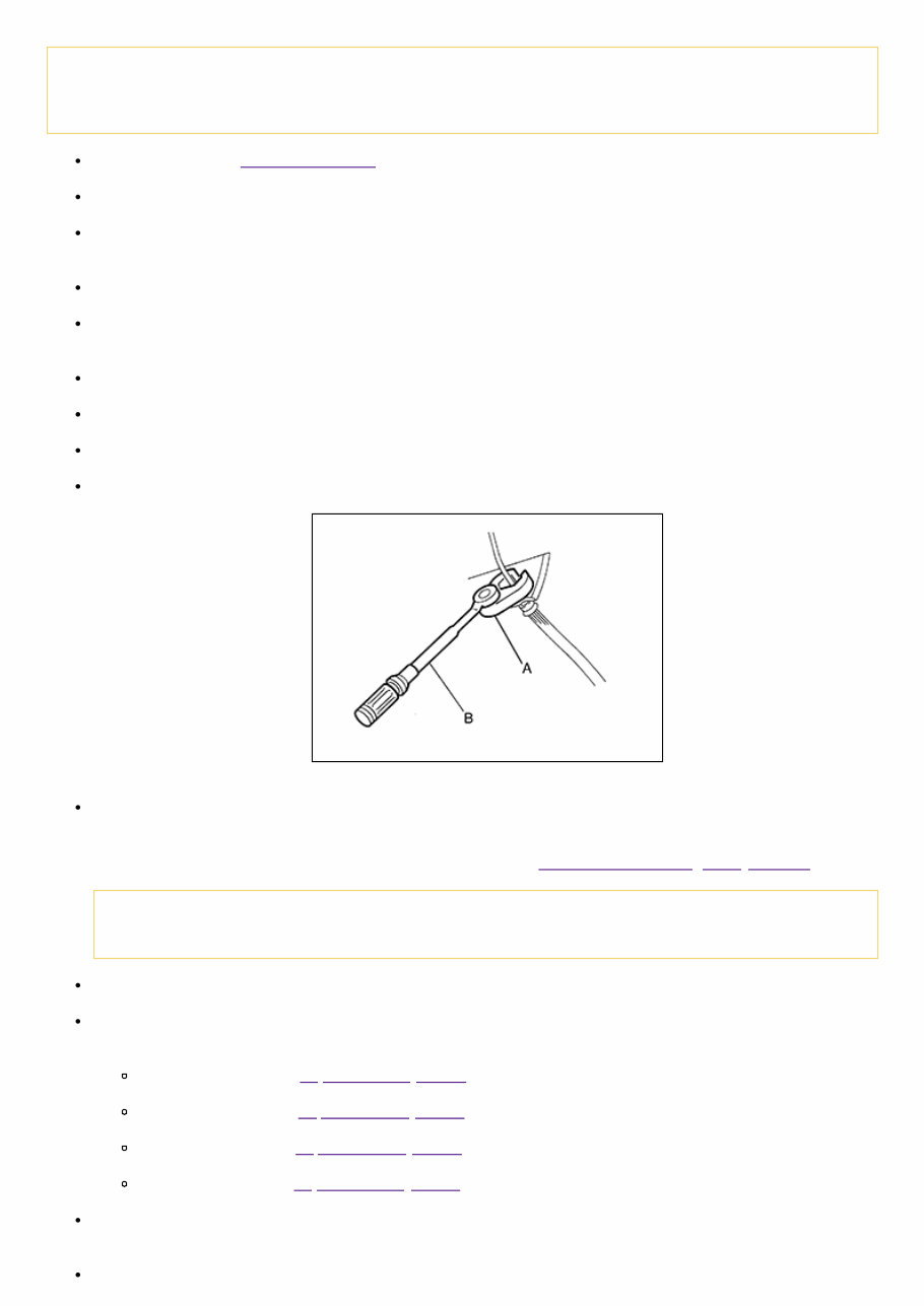
Precaution for Brake System WARNING: Since dust covering the front and rear brakes has an affect on human body, the dust must be removed with a dust collector. Never splatter the dust with an air blow gun. Brake fluid use refer to Fluids and Lubricants. Never reuse drained brake fluid. Never spill or splash brake fluid on painted surfaces. Brake fluid may seriously damage paint. Wipe it off immediately and wash with water if it gets on a painted surface. For brake component parts, never wash them with water. Always confirm the specified tightening torque when installing the brake pipes. After pressing the brake pedal more deeply or harder than normal driving, such as air bleeding, check each item of brake pedal. Adjust brake pedal if it is outside the standard value. Always clean with new brake fluid when cleaning the brake caliper and other components. Never use mineral oils such as gasoline or light oil to clean. They may damage rubber parts and cause improper operation. Always loosen the brake tube flare nut with a flare nut wrench. Tighten the brake tube flare nut to the specified torque with a crowfoot (A) and torque wrench (B). NISSK0000000006960634-01-JPFIA0001ZZ Turn the power switch OFF and disconnect CONSULT from data link connector. Get out of the vehicle, close all doors (including back door), check that the room lamp is OFF, and wait for 3 minutes or more without opening these doors. Disconnect the electrically-driven intelligent brake unit, the ABS actuator and electric unit (control unit) harness connector or the 12V battery negative terminal before performing the work. Refer to Precautions for Removing Battery Terminal. CAUTION: Never operate the vehicle. Check that no brake fluid leakage is present after replacing the parts. Burnish the brake contact surfaces after refinishing or replacing rotors, after replacing pads, or if a soft pedal occurs at very low mileage. Front brake pad: Refer to Inspection and Adjustment. Front disc rotor: Refer to Inspection and Adjustment. Rear brake pad: Refer to Inspection and Adjustment. Rear disc rotor: Refer to Inspection and Adjustment. When the brake pedal is operated, an operating sound may be heard from the electrically-driven intelligent brake unit. This occurs when the electrically-driven intelligent brake unit is operating normally and is not a malfunction. When the brake pedal is depressed when the EV system is not started, the brake pedal will feel heavy and the stroke will be shorter. When the unfamiliar feeling disappears and the brake warning lamp is OFF after the brake pedal was depressed, then
this is not a malfunction. When the brake warning lamp is ON, use CONSULT and perform the “BRAKE” self diagnosis. When there is a malfunction in the power system of the electrically-driven intelligent brake unit (no voltage is generated), voltage is temporarily supplied to the electrically-driven intelligent brake unit from the brake power supply backup unit. At the same time, the brake warning lamp (red) and brake system warning lamp (yellow) turn ON, and the warning buzzer sounds. When a malfunction occurs in the electrically-driven intelligent brake unit, the VDC function performs control (boost operation). When a malfunction occurs in the DC/DC-J/B and 12V battery, the braking force is determined by the force pressing on the brake pedal (no boost operation). At the same time, the brake warning lamp (red) and the brake system warning lamp (yellow) turns ON. When a malfunction occurs in the electrically-driven intelligent brake and in the VDC function, the braking force is determined by the force pressing on the brake pedal (no boost operation). At the same time, the brake warning lamp (red) and brake system warning lamp (yellow) turn ON. When a malfunction occurs in the electrically-driven intelligent brake, VDC function, and power system, then cooperative regenerative brake control is not performed. When a malfunction occurs in the brake power supply backup unit, the brake system warning lamp (yellow) turns ON.
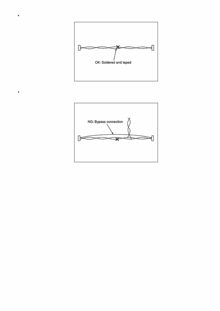
Precaution for Harness Repair Solder the repair part, and wrap it with tape. [Twisted wire fray must be 110 mm (4.33 in) or less.] NISSK0000000006960635-01-SKIB8766E Never bypass the repair point with wire. (If it is bypassed, the turnout point cannot be separated and the twisted wire characteristics are lost.) NISSK0000000006960635-02-SKIB8767E
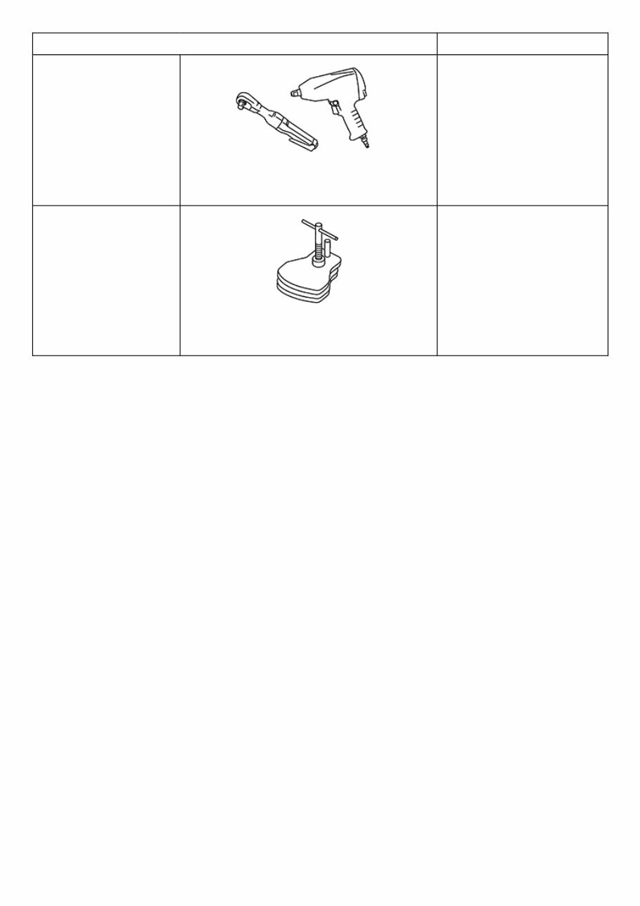
Commercial Service Tools Tool name Description Power tool NISSK0000000006960636-01- PBIC0190E Loosening bolts and nuts Brake caliper wrench NISSK0000000006960636-02- NNFIA0040ZZ Return the piston
The 2011 Nissan LEAF Service & Repair Manual is the ultimate resource for maintaining and repairing your vehicle. Whether you prefer a DIY approach or simply want to understand your vehicle better, this manual has got you covered.
With step-by-step instructions, troubleshooting charts, and detailed illustrations, this manual provides all the information you need to fix any problems that may arise with your Nissan LEAF. And with its compatibility with various electronic devices, you can easily access the manual anytime, anywhere.
Regular maintenance is crucial for any vehicle, and the Nissan LEAF is no exception. With this manual, you can save on repair costs and increase your vehicle's reliability. No more flipping through hundreds of pages or dealing with greasy, torn, or lost pages.
Whether you prefer a digital version or a physical copy, this manual has you covered. It's printable and compatible with various devices, making it a convenient and practical resource for any Nissan LEAF owner.