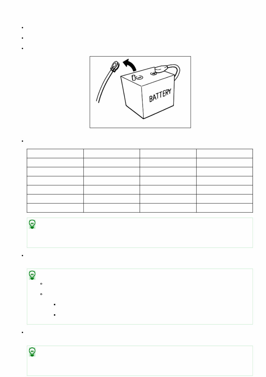
PRECAUTIONS FOR REMOVING BATTERY TERMINAL : Precautions NIS0000000009926246 When disconnecting the battery terminal, pay attention to the following. Always use a 12V battery as power source. Never disconnect battery terminal while engine is running. When removing the 12V battery terminal, turn OFF the ignition switch and wait at least 30 seconds. NIS0000000009926246-01-EF289H For vehicles with the engine listed below, remove the battery terminal after a lapse of the specified time: BR08DE : 4 minutes R9M engine : 4 minutes BR10DE : 12 minutes V9X engine : 4 minutes D4D engine : 20 minutes YD25DDTi : 2 minutes HR09DET : 12 minutes YS23DDT : 4 minutes HRA2DDT : 12 minutes YS23DDTT : 4 minutes K9K engine : 4 minutes ZD30DDTi : 60 seconds M9R engine : 4 minutes ZD30DDTT : 60 seconds NOTE: ECU may be active for several tens of seconds after the ignition switch is turned OFF. If the battery terminal is removed before ECU stops, then a DTC detection error or ECU data corruption may occur. After high-load driving, if the vehicle is equipped with the V9X engine, turn the ignition switch OFF and wait for at least 15 minutes to remove the battery terminal. NOTE: Turbocharger cooling pump may operate in a few minutes after the ignition switch is turned OFF. Example of high-load driving Driving for 30 minutes or more at 140 km/h (86 MPH) or more. Driving for 30 minutes or more on a steep slope. For vehicles with the 2-batteries, be sure to connect the main battery and the sub battery before turning ON the ignition switch. NOTE: If the ignition switch is turned ON with any one of the terminals of main battery and sub battery disconnected, then DTC may be detected.
After installing the 12V battery, always check "Self Diagnosis Result" of all ECUs and erase DTC. NOTE: The removal of 12V battery may cause a DTC detection error.
Precaution for Supplemental Restraint System (SRS) "AIR BAG" and "SEAT BELT PRE-TENSIONER" The Supplemental Restraint System such as “AIR BAG” and “SEAT BELT PRE-TENSIONER”, used along with a front seat belt, helps to reduce the risk or severity of injury to the driver and front passenger for certain types of collision. This system includes seat belt switch inputs and dual stage front air bag modules. The SRS system uses the seat belt switches to determine the front air bag deployment, and may only deploy one front air bag, depending on the severity of a collision and whether the front occupants are belted or unbelted. Information necessary to service the system safely is included in the “SRS AIR BAG” and “SEAT BELT” of this Service Manual. WARNING: Always observe the following items for preventing accidental activation. To avoid rendering the SRS inoperative, which could increase the risk of personal injury or death in the event of a collision that would result in air bag inflation, it is recommended that all maintenance and repair be performed by an authorized NISSAN/INFINITI dealer. Improper repair, including incorrect removal and installation of the SRS, can lead to personal injury caused by unintentional activation of the system. For removal of Spiral Cable and Air Bag Module, see “SRS AIR BAG”. Never use electrical test equipment on any circuit related to the SRS unless instructed to in this Service Manual. SRS wiring harnesses can be identified by yellow and/or orange harnesses or harness connectors. PRECAUTIONS WHEN USING POWER TOOLS (AIR OR ELECTRIC) AND HAMMERS WARNING: Always observe the following items for preventing accidental activation. When working near the Air Bag Diagnosis Sensor Unit or other Air Bag System sensors with the ignition ON or engine running, never use air or electric power tools or strike near the sensor(s) with a hammer. Heavy vibration could activate the sensor(s) and deploy the air bag(s), possibly causing serious injury. When using air or electric power tools or hammers, always switch the ignition OFF, disconnect the battery or batteries, and wait at least 3 minutes before performing any service.
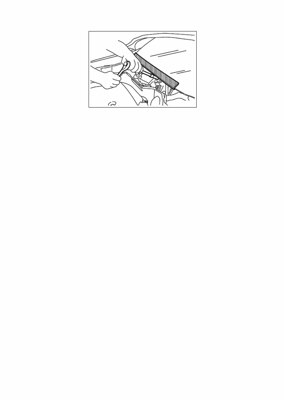
Precaution for Procedure without Cowl Top Cover When performing the procedure after removing cowl top cover, cover the lower end of windshield with urethane, etc to prevent damage to windshield. NISC0000000013989509-01-PIIB3706J
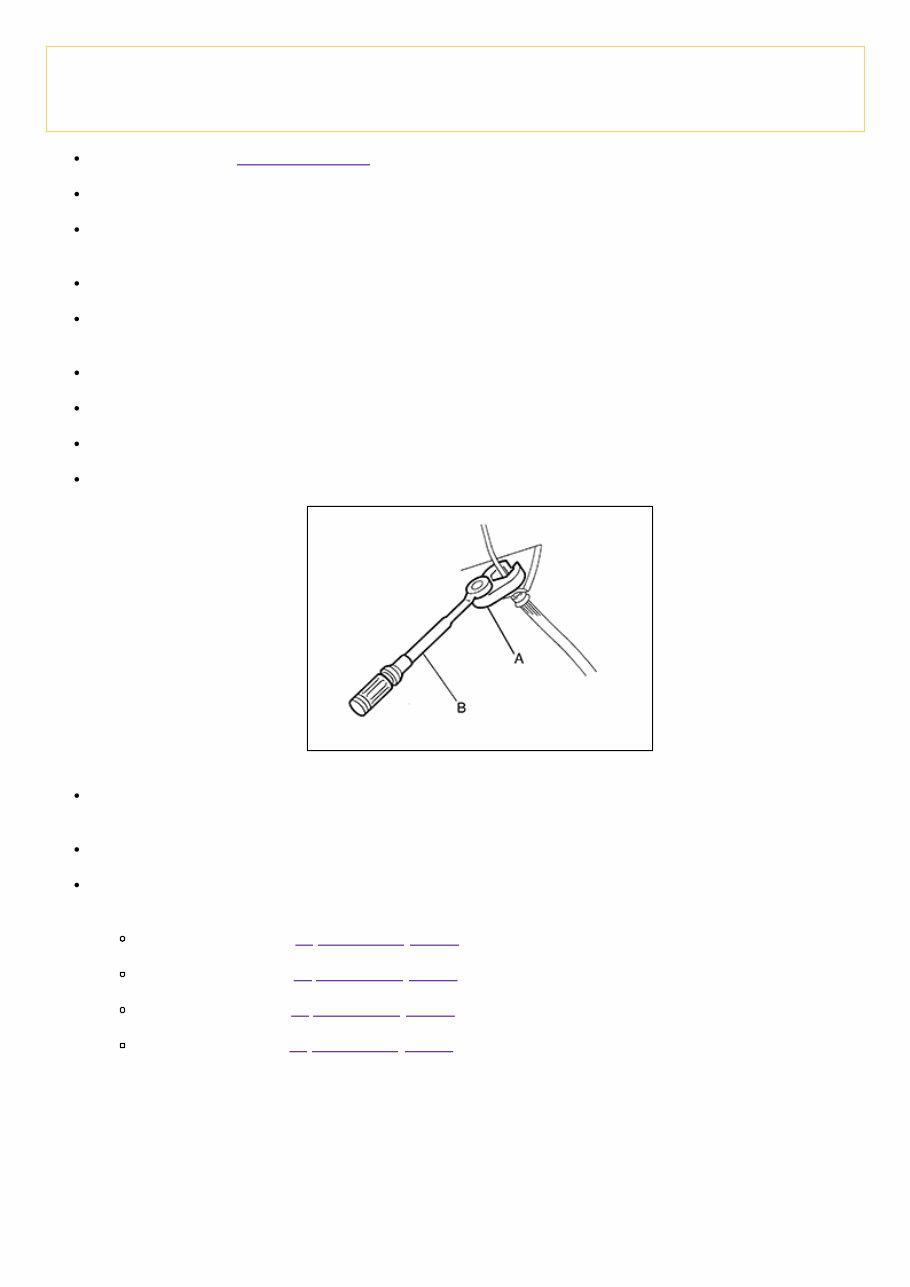
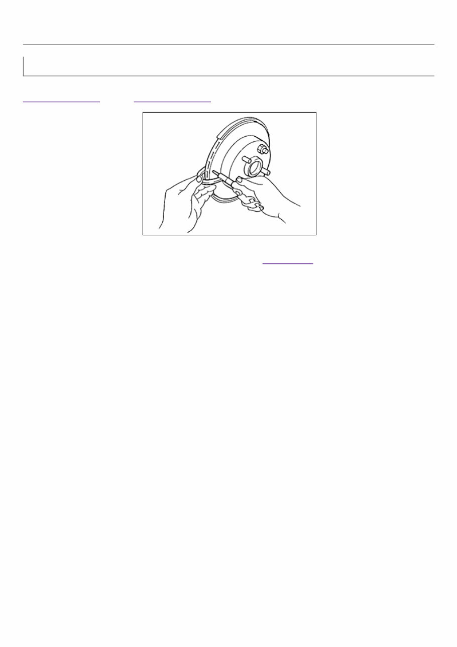
Precaution for Brake System WARNING: Since dust covering the front and rear brakes has an affect on human body, the dust must be removed with a dust collector. Never splatter the dust with an air blow gun. Brake fluid use refer to Fluids and Lubricants. Never reuse drained brake fluid. Never spill or splash brake fluid on painted surfaces. Brake fluid may seriously damage paint. Wipe it off immediately and wash with water if it gets on a painted surface. For brake component parts, never wash them with water. Always confirm the specified tightening torque when installing the brake pipes. After pressing the brake pedal more deeply or harder than normal driving, such as air bleeding, check each item of brake pedal. Adjust brake pedal if it is outside the standard value. Always clean with new brake fluid when cleaning the master cylinder, brake caliper and other components. Never use mineral oils such as gasoline or light oil to clean. They may damage rubber parts and cause improper operation. Always loosen the brake tube flare nut with a flare nut wrench. Tighten the brake tube flare nut to the specified torque with a crowfoot (A) and torque wrench (B). NISC0000000013989510-01-JPFIA0001ZZ Turn the ignition switch OFF and disconnect the ABS actuator and electric unit (control unit) harness connector or the battery negative terminal before performing the work. Check that no brake fluid leakage is present after replacing the parts. Burnish the brake contact surfaces after refinishing or replacing rotors, after replacing pads, or if a soft pedal occurs at very low mileage. Front brake pad: Refer to Inspection and Adjustment. Front disc rotor: Refer to Inspection and Adjustment. Rear brake pad: Refer to Inspection and Adjustment. Rear disc rotor: Refer to Inspection and Adjustment.
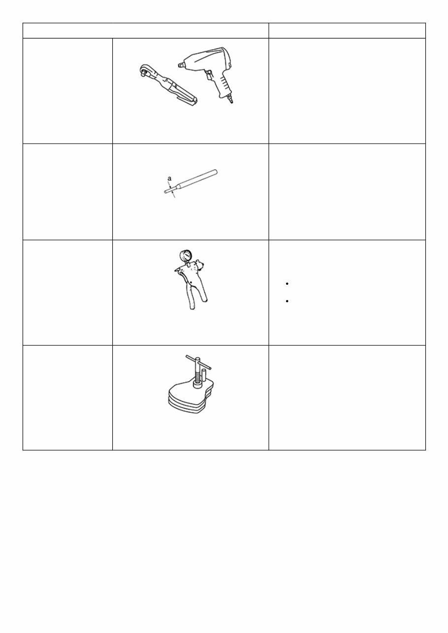
Commercial Service Tool Tool name Description Power tool NISC0000000013989512-01- PBIC0190E Loosening bolts and nuts Pin punch a: 4 mm (0.16 in) NISC0000000013989512-02-NT410 Removing and installing reservoir tank Handy vacuum pump NISC0000000013989512-03- ZZC1313D Air tight Inspection of check valve Brake caliper wrench NISC0000000013989512-04- NNFIA0040ZZ Return the piston
Inspection INSPECTION Uneven wear Check the uneven wear of the disc rotor using a micrometer. Replace the disc rotor if the thickness is below the wear limit. Refer to Removal and Installation (2WD) or Removal and Installation (AWD). NISC0000000013989514-01-SBR020B Thickness variation (measured at 8 positions) : Refer to Rear Disc Brake.
Inspection INSPECTION Uneven wear Check the uneven wear of the disc rotor using a micrometer. Replace the disc rotor if the thickness is below the wear limit. Refer to Removal and Installation (for Nismo ) or Removal and Installation (except for Nismo ) NISC0000000013989513-01-SBR020B Thickness variation (measured at 8 positions) : Refer to Front Disc Brake.
Use the chart below to find the cause of the symptom. If necessary, repair or replace these parts. Reference page Inspection and Adjustment, Inspection and Adjustment Inspection and Adjustment, Inspection and Adjustment Inspection, Inspection Inspection and Adjustment, Inspection and Adjustment, Inspection, Inspection Inspection and Adjustment, Inspection and Adjustment, Inspection, Inspection Inspection and Adjustment, Inspection and Adjustment Inspection and Adjustment, Inspection and Adjustment Inspection and Adjustment, Inspection and Adjustment Inspection and Adjustment, Inspection and Adjustment Inspection and Adjustment , Inspection and Adjustment , Inspection , Inspection NVH in PB section NVH in DLN section NVH in D sectio Possible cause and SUSPECTED PARTS Pads damaged Pads uneven wear Shims damaged Rotor imbalance Rotor damage Rotor runout Rotor deformation Rotor deflection Rotor rust Rotor thickness variation Drum out of round PROPELLER SHAFT DIFFEREN Symptom BRAKE Noise × × × × × × Shake × × Shimmy, Judder × × × × × × × × ×: Applicable
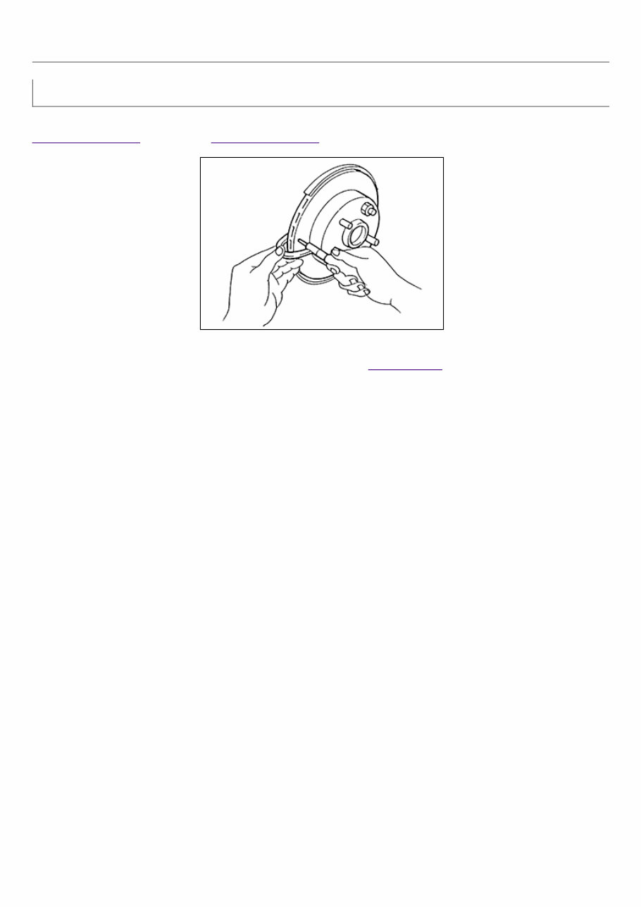
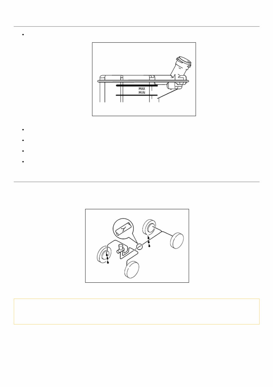
Inspection BRAKE FLUID LEVEL Check that the fluid level in the reservoir tank is within the specified range (MAX – MIN lines). NISC0000000013989517-01-SFIA2634J Visually check for any brake fluid leakage around the reservoir tank. Check the brake system for any leakage if the fluid level is extremely low (lower than MIN). Check the brake system for fluid leakage if the warning lamp remains illuminated even after the parking brake is released. Check the reservoir tank for the mixing of foreign matter (e.g. dust) and oils other than brake fluid. BRAKE LINE 1 Check brake line (tubes and hoses) for cracks, deterioration or other damage. Replace any damaged parts. 2 Depress the brake pedal with a force of 785 N (80 kg, 176 lb) and hold down the pedal for approximately 5 seconds with the engine running. Check for any fluid leakage. NISC0000000013989517-02-SBR389C CAUTION: Retighten the applicable connection to the specified torque and repair any abnormal (damaged, worn or deformed) part if any brake fluid leakage is present.
Keep your 2017 Nissan Juke running smoothly and efficiently with the help of the official service & repair manual. This comprehensive repair manual provides you with all the necessary information and instructions to troubleshoot and replace any parts on your vehicle. Step-by-step instructions, clear images, and exploded-view illustrations make it easy to fix any issues that may arise.
Regular maintenance is crucial for the longevity of your vehicle, and with the manufacturer's recommended troubleshooting charts and replacement procedures, this manual has you covered. By following these recommendations, you can save on costly repairs, increase your vehicle's reliability, and avoid frequent trips to the repair shop.
The 2017 Nissan Juke service & repair manual includes every troubleshooting and replacement procedure provided by the manufacturer. No need to search through hundreds of pages or worry about greasy, torn, or lost pages. You can easily carry this manual with you, search for specific information, and even bookmark important pages for future reference.
In addition to its electronic format, this manual is also printable for those who prefer a physical copy. Compatible with various devices such as computers, smartphones, and tablets, this manual is easily accessible anytime, anywhere. All you need is Adobe Reader (free) to view the manual.