Precaution for Supplemental Restraint System (SRS) "AIR BAG" and "SEAT BELT PRE-TENSIONER" The Supplemental Restraint System such as “AIR BAG” and “SEAT BELT PRE-TENSIONER”, used along with a front seat belt, helps to reduce the risk or severity of injury to the driver and front passenger for certain types of collision. This system includes seat belt switch inputs and dual stage front air bag modules. The SRS system uses the seat belt switches to determine the front air bag deployment, and may only deploy one front air bag, depending on the severity of a collision and whether the front occupants are belted or unbelted. Information necessary to service the system safely is included in the “SRS AIR BAG” and “SEAT BELT” of this Service Manual. WARNING: Always observe the following items for preventing accidental activation. To avoid rendering the SRS inoperative, which could increase the risk of personal injury or death in the event of a collision that would result in air bag inflation, it is recommended that all maintenance and repair be performed by an authorized NISSAN/INFINITI dealer. Improper repair, including incorrect removal and installation of the SRS, can lead to personal injury caused by unintentional activation of the system. For removal of Spiral Cable and Air Bag Module, see “SRS AIR BAG”. Never use electrical test equipment on any circuit related to the SRS unless instructed to in this Service Manual. SRS wiring harnesses can be identified by yellow and/or orange harnesses or harness connectors. PRECAUTIONS WHEN USING POWER TOOLS (AIR OR ELECTRIC) AND HAMMERS WARNING: Always observe the following items for preventing accidental activation. When working near the Air Bag Diagnosis Sensor Unit or other Air Bag System sensors with the ignition ON or engine running, never use air or electric power tools or strike near the sensor(s) with a hammer. Heavy vibration could activate the sensor(s) and deploy the air bag(s), possibly causing serious injury. When using air or electric power tools or hammers, always switch the ignition OFF, disconnect the battery or batteries, and wait at least 3 minutes before performing any service.
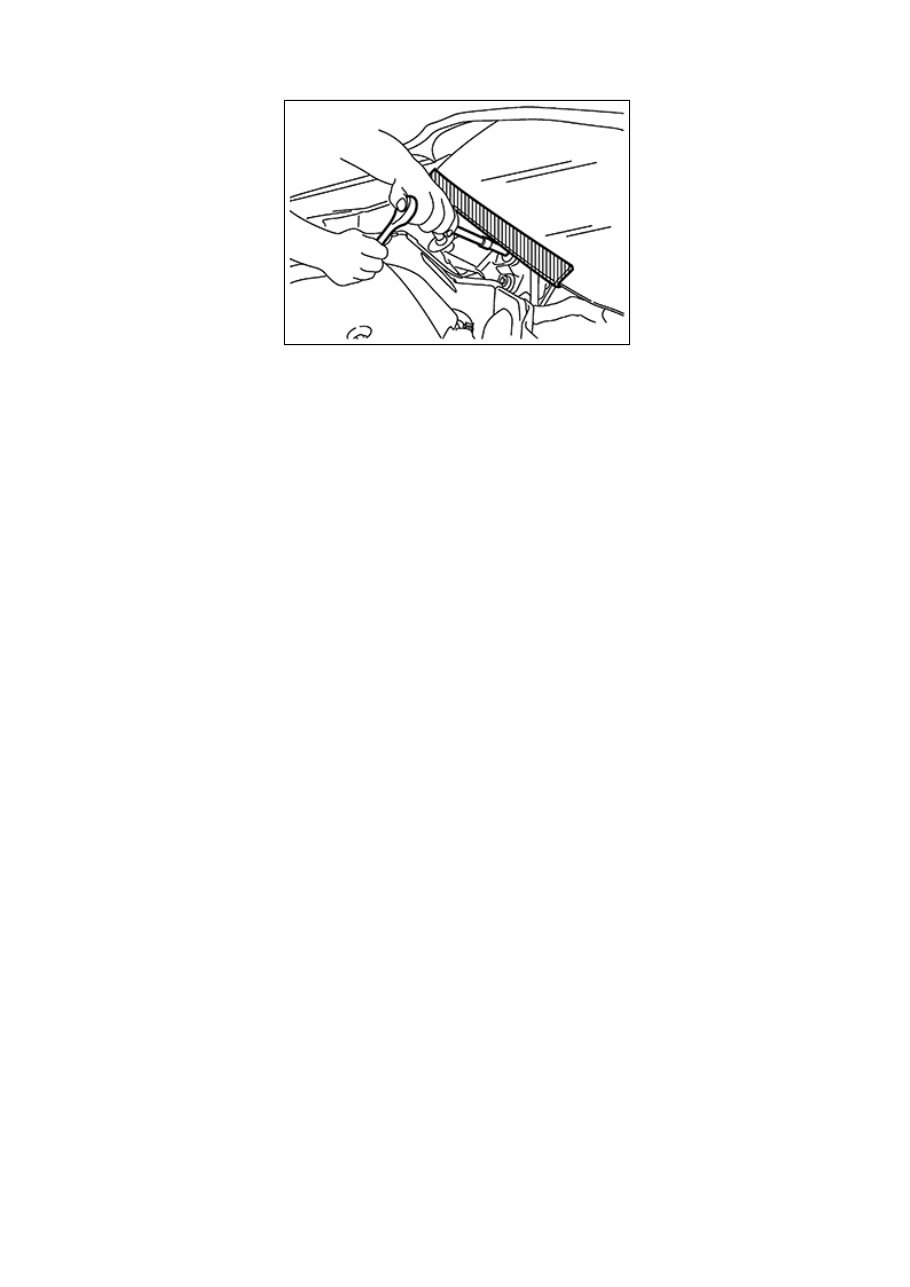
Precaution for Procedure without Cowl Top Cover When performing the procedure after removing cowl top cover, cover the lower end of windshield with urethane, etc to prevent damage to windshield. NISX0000000006765776-01-PIIB3706J
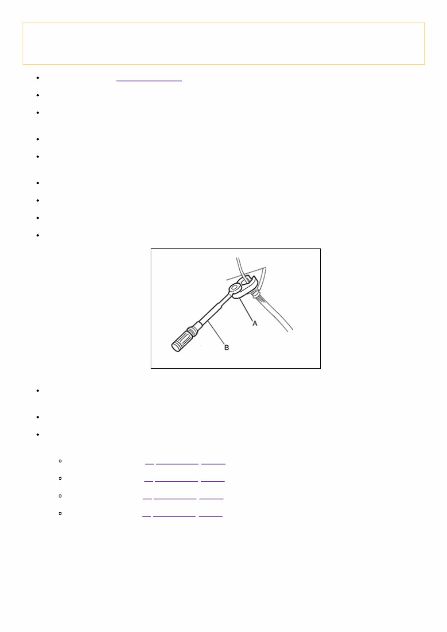
Precaution for Brake System WARNING: Since dust covering the front and rear brakes has an affect on human body, the dust must be removed with a dust collector. Never splatter the dust with an air blow gun. Brake fluid use refer to Fluids and Lubricants. Never reuse drained brake fluid. Never spill or splash brake fluid on painted surfaces. Brake fluid may seriously damage paint. Wipe it off immediately and wash with water if it gets on a painted surface. For brake component parts, never wash them with water. Always confirm the specified tightening torque when installing the brake pipes. After pressing the brake pedal more deeply or harder than normal driving, such as air bleeding, check each item of brake pedal. Adjust brake pedal if it is outside the standard value. Always clean with new brake fluid when cleaning the master cylinder, brake caliper and other components. Never use mineral oils such as gasoline or light oil to clean. They may damage rubber parts and cause improper operation. Always loosen the brake tube flare nut with a flare nut wrench. Tighten the brake tube flare nut to the specified torque with a crowfoot (A) and torque wrench (B). NISX0000000006713876-01-JPFIA0001ZZ Turn the ignition switch OFF and disconnect the ABS actuator and electric unit (control unit) harness connector or the battery negative terminal before performing the work. Check that no brake fluid leakage is present after replacing the parts. Burnish the brake contact surfaces after refinishing or replacing rotors, after replacing pads, or if a soft pedal occurs at very low mileage. Front brake pad: Refer to Inspection and Adjustment. Front disc rotor: Refer to Inspection and Adjustment. Rear brake pad: Refer to Inspection and Adjustment. Rear disc rotor: Refer to Inspection and Adjustment.
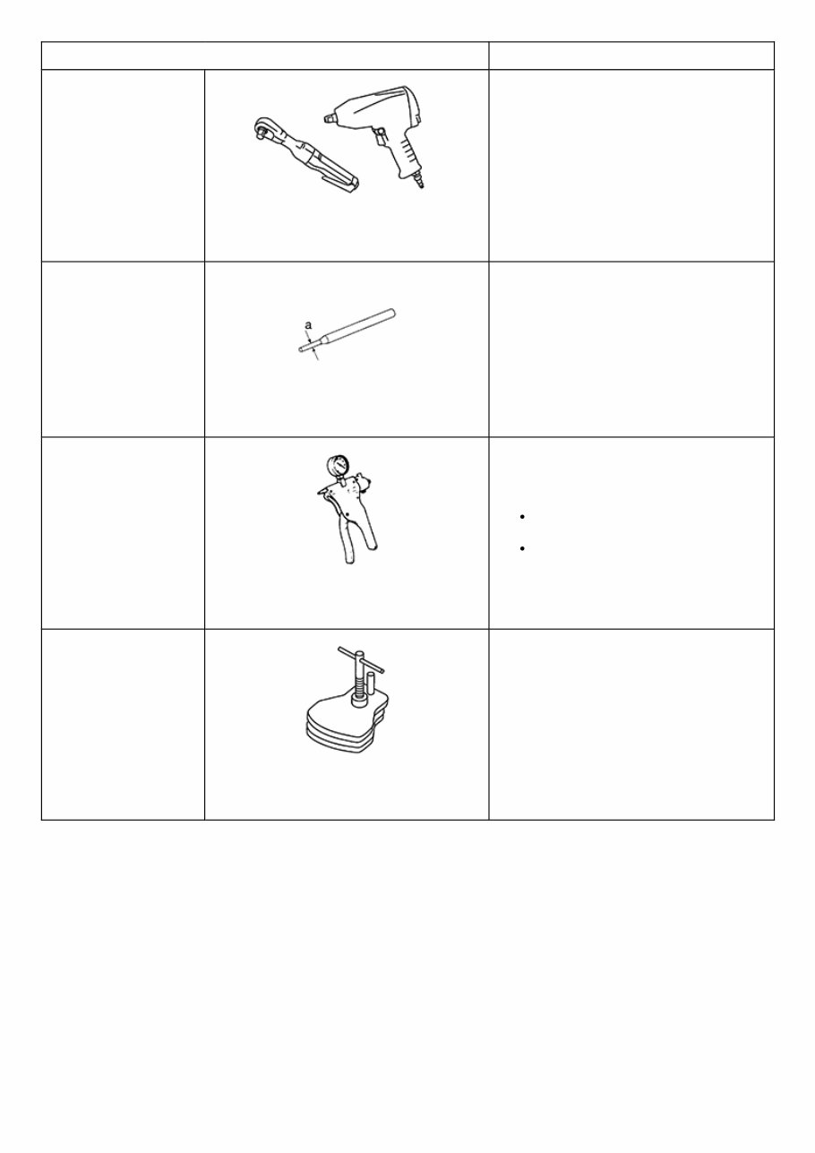
Commercial Service Tool Tool name Description Power tool NISX0000000006713877-01- PBIC0190E Loosening bolts and nuts Pin punch a: 4 mm (0.16 in) NISX0000000006713877-02-NT410 Removing and installing reservoir tank Handy vacuum pump NISX0000000006713877-03- ZZC1313D Air tight Inspection of check valve Brake caliper wrench NISX0000000006713877-04- NNFIA0040ZZ Return the piston
Use the chart below to find the cause of the symptom. If necessary, repair or replace these parts. Reference page Inspection and Adjustment, Inspection and Adjustment Inspection and Adjustment, Inspection and Adjustment Inspection, Inspection Inspection and Adjustment, Inspection and Adjustment Inspection and Adjustment, Inspection and Adjustment Inspection and Adjustment, Inspection and Adjustment Inspection and Adjustment, Inspection and Adjustment Inspection and Adjustment, Inspection and Adjustment Inspection and Adjustment, Inspection and Adjustment Inspection and Adjustment , Inspection and Adjustment NVH in PB section NVH in DLN section NVH in D sectio Possible cause and SUSPECTED PARTS Pads damaged Pads uneven wear Shims damaged Rotor imbalance Rotor damage Rotor runout Rotor deformation Rotor deflection Rotor rust Rotor thickness variation Drum out of round PROPELLER SHAFT DIFFEREN Symptom BRAKE Noise × × × × × × Shake × × Shimmy, Judder × × × × × × × × ×: Applicable
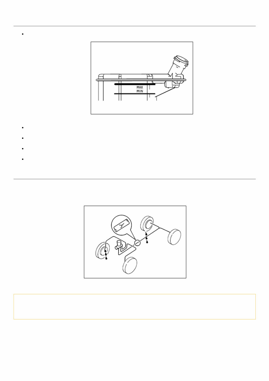
Inspection BRAKE FLUID LEVEL Check that the fluid level in the reservoir tank is within the specified range (MAX – MIN lines). NISX0000000006713880-01-SFIA2634J Visually check for any brake fluid leakage around the reservoir tank. Check the brake system for any leakage if the fluid level is extremely low (lower than MIN). Check the brake system for fluid leakage if the warning lamp remains illuminated even after the parking brake is released. Check the reservoir tank for the mixing of foreign matter (e.g. dust) and oils other than brake fluid. BRAKE LINE 1 Check brake line (tubes and hoses) for cracks, deterioration or other damage. Replace any damaged parts. 2 Depress the brake pedal with a force of 785 N (80 kg, 176 lb) and hold down the pedal for approximately 5 seconds with the engine running. Check for any fluid leakage. NISX0000000006713880-02-SBR389C CAUTION: Retighten the applicable connection to the specified torque and repair any abnormal (damaged, worn or deformed) part if any brake fluid leakage is present.
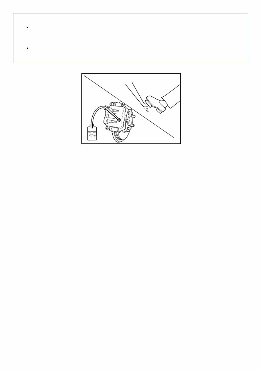
Draining CAUTION: Never spill or splash brake fluid on painted surfaces. Brake fluid may seriously damage paint. Wipe it off immediately and wash with water if it gets on a painted surface. For brake component parts, never wash them with water. Turn the ignition switch OFF and disconnect the ABS actuator and electric unit (control unit) harness connector or the battery negative terminal before performing work. 1 Connect a vinyl tube to the bleed valve. NISX0000000006713881-01-BRA0007D 2 Depress the brake pedal and loosen the bleeder valve to gradually discharge brake fluid.
Refilling CAUTION: Turn the ignition switch OFF and disconnect the ABS actuator and electric unit (control unit) harness connector or the battery negative terminal before performing work. Never spill or splash brake fluid on painted surfaces. Brake fluid may seriously damage paint. Wipe it off immediately and wash with water if it gets on a painted surface. For brake component parts, never wash them with water. 1 Check that there is no foreign material in the reservoir tank, and refill with new brake fluid. CAUTION: Never reuse drained brake fluid. Never allow foreign matter (e.g. dust) and oils other than brake fluid to enter the reservoir tank. 2 Loosen the bleeder valve, slowly depress the brake pedal to the full stroke, and then release the pedal. Repeat this operation at intervals of 2 or 3 seconds until new brake fluid is discharged. Then close the bleeder valve with the brake pedal depressed. Repeat the same work on each wheel. 3 Perform the air bleeding. Refer to Bleeding Brake System.
Bleeding Brake System CAUTION: Turn the ignition switch OFF and disconnect the ABS actuator and electric unit (control unit) harness connector or the battery negative terminal before performing the work. Monitor the fluid level in the reservoir tank while performing the air bleeding Never spill or splash brake fluid on painted surfaces. Brake fluid may seriously damage paint. Wipe it off immediately and wash with water if it gets on a painted surface. For brake component parts, never wash them with water. 1 Check that there is no foreign material in the reservoir tank, and refill with new brake fluid. CAUTION: Never reuse drained brake fluid. Never allow oils other than brake fluid to enter the reservoir tank. 2 Connect a vinyl tube to the bleeder valve of the rear right brake. 3 Fully depress the brake pedal 4 to 5 times. 4 Loosen the bleeder valve and bleed air with the brake pedal depressed, and then quickly tighten the bleeder valve. 5 Repeat steps 3 and 4 until all of the air is out of the brake line. 6 Tighten the bleeder valve to the specified torque. Front disc brake: refer to Exploded View. Rear disc brake: refer to Exploded View. 7 Perform steps 2 to 6. Occasionally fill with the brake fluid in order to keep it in the reservoir tank at least half of MAX line. Bleed air in the following order: rear right brake → front left brake → rear left brake → and front right brake in order. 8 Check that the fluid level in the reservoir tank is within the specified range after air bleeding. Refer to Inspection. 9 Check each item of brake pedal. Adjust it if the measurement value is not the standard. Refer to Inspection and Adjustment.
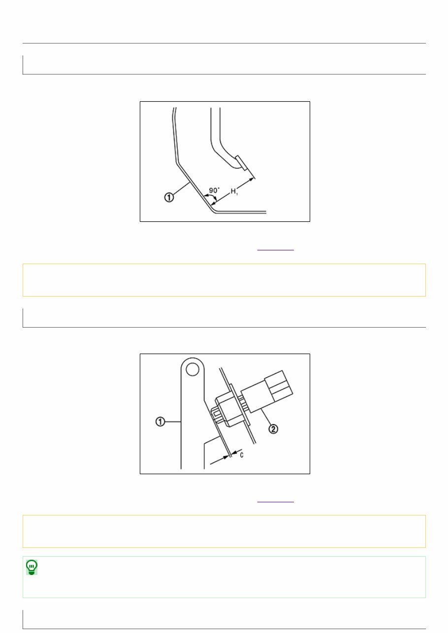
Inspection and Adjustment INSPECTION Brake Pedal Height Check the height (H 1 ) between the dash lower panel (1) and the brake pedal upper surface. NISX0000000006713879-01-JPFIA0065ZZ H 1 : Refer to Brake Pedal. CAUTION: Remove the floor trim. Stop Lamp Switch Check the clearance (C) among the brake pedal lever (1) and the stop lamp switch (2) threaded end. NISX0000000006713879-02-PFIA0813J C : Refer to Brake Pedal. CAUTION: The stop lamp must turn off when the brake pedal is released. NOTE: Pull the brake pedal pad to make the clearance between the stop lamp switch threaded end and the brake peal lever. Brake Pedal Position Switch
The 2011 Nissan Juke Service & Repair Manual is the ultimate DIY guide for fixing any issues with your vehicle. With step-by-step instructions, clear images, and exploded-view illustrations provided by the manufacturer, you'll have all the necessary tools to troubleshoot and replace any faulty parts. The manual is compatible with various electronic devices, making it easily accessible anytime and anywhere.
Regular maintenance is crucial for keeping your vehicle in top shape, and this manual provides the manufacturer's recommended troubleshooting charts and replacement procedures. By following these instructions, you'll not only save on repairs but also increase your vehicle's reliability, keeping the repair shop at bay.
Gone are the days of flipping through hundreds of pages or dealing with greasy, torn, or lost pages. The electronic format allows you to easily carry the manual, search for specific information, take screenshots, and bookmark pages. And if you prefer a physical copy, you can easily print it out for reference.
The 2011 Nissan Juke Service & Repair Manual is available in English and compatible with any electronic device, including PC and Mac computers, smartphones, and tablets. All you need is Adobe Reader to access it for free. Don't let vehicle problems slow you down - get your hands on this comprehensive repair manual and keep your Juke running like new.