Precaution for Supplemental Restraint System (SRS) "AIR BAG" and "SEAT BELT PRE-TENSIONER" NISD0000000014654458 The Supplemental Restraint System such as “AIR BAG” and “SEAT BELT PRE-TENSIONER”, used along with a front seat belt, helps to reduce the risk or severity of injury to the driver and front passenger for certain types of collisions. Information necessary to service the system safely is included in the “SRS AIR BAG” and “SEAT BELT” sections of this Service Manual. WARNING: Always observe the following items for preventing accidental activation: To avoid rendering the SRS inoperative, which could increase the risk of personal injury or death in the event of a collision that would result in air bag inflation, it is recommended that all maintenance and repair be performed by an authorized NISSAN/INFINITI dealer. Improper repair, including incorrect removal and installation of the SRS, can lead to personal injury caused by unintentional activation of the system. For removal of Spiral Cable and Air Bag Module, see “SRS AIR BAG”. Never use electrical test equipment on any circuit related to the SRS unless instructed to in this Service Manual. SRS wiring harnesses can be identified by yellow and/or orange harnesses or harness connectors. PRECAUTIONS WHEN USING POWER TOOLS (AIR OR ELECTRIC) AND HAMMERS WARNING: Always observe the following items for preventing accidental activation: When working near the Air Bag Diagnosis Sensor Unit or other Air Bag System sensors with the ignition/power switch ON or engine running, never use air or electric power tools or strike near the sensor(s) with a hammer. Heavy vibration could activate the sensor(s) and deploy the air bag(s), possibly causing serious injury. When using air or electric power tools or hammers, always switch the ignition/power switch OFF, disconnect the 12V battery or batteries, and wait at least 3 minutes before performing any service.
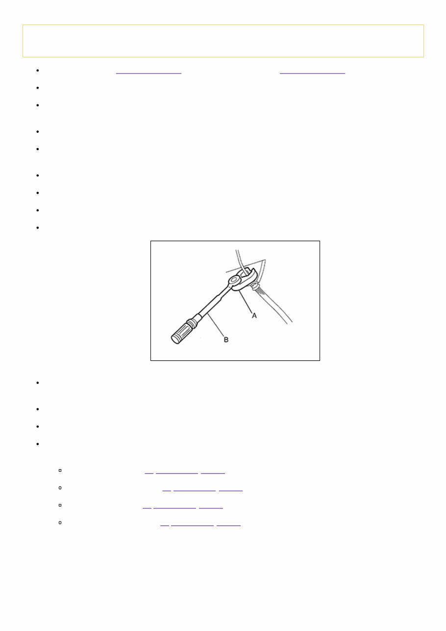
Precaution for Brake System RDE-001192223 WARNING: Clean any dust from the front brake and rear brake with a vacuum dust collector. Do not blow with compressed air. Brake fluid use refer to Fluids and Lubricants (United States and Canada) and Fluids and Lubricants (Mexico). Do not reuse drained brake fluid. Do not spill or splash brake fluid on painted surfaces. Brake fluid may seriously damage paint. Wipe it off immediately and wash with water if it gets on a painted surface. Always confirm the specified tightening torque when installing the brake pipes. After pressing the brake pedal more deeply or harder than normal driving, such as air bleeding, inspect the brake pedal height and play. Adjust brake pedal if it is outside the standard value. Always clean with new brake fluid when cleaning the brake caliper and other components. Do not use mineral oils such as gasoline or light oil to clean. They may damage rubber parts and cause improper operation. Always loosen the brake tube flare nut with a flare nut wrench. Tighten the brake tube flare nut to the specified torque with a crowfoot (A) and torque wrench (B). RDE-001192223-01-PFIA0001ZZ Brake system is an important safety part. If a brake fluid leak is detected, always disassemble the affected part. If a malfunction is detected, replace part with a new one. Always connect the battery terminals when moving the vehicle. Check that no brake fluid leakage is present after replacing the parts. Burnish the brake contact surfaces after refinishing or replacing disc brake rotors, after replacing brake pads, or if a soft pedal occurs at very low mileage. Front brake pad: Refer to Inspection and Adjustment. Front disc brake rotor: Refer to Inspection and Adjustment. Rear brake pad: Refer to Inspection and Adjustment. Rear disc brake rotor: Refer to Inspection and Adjustment.
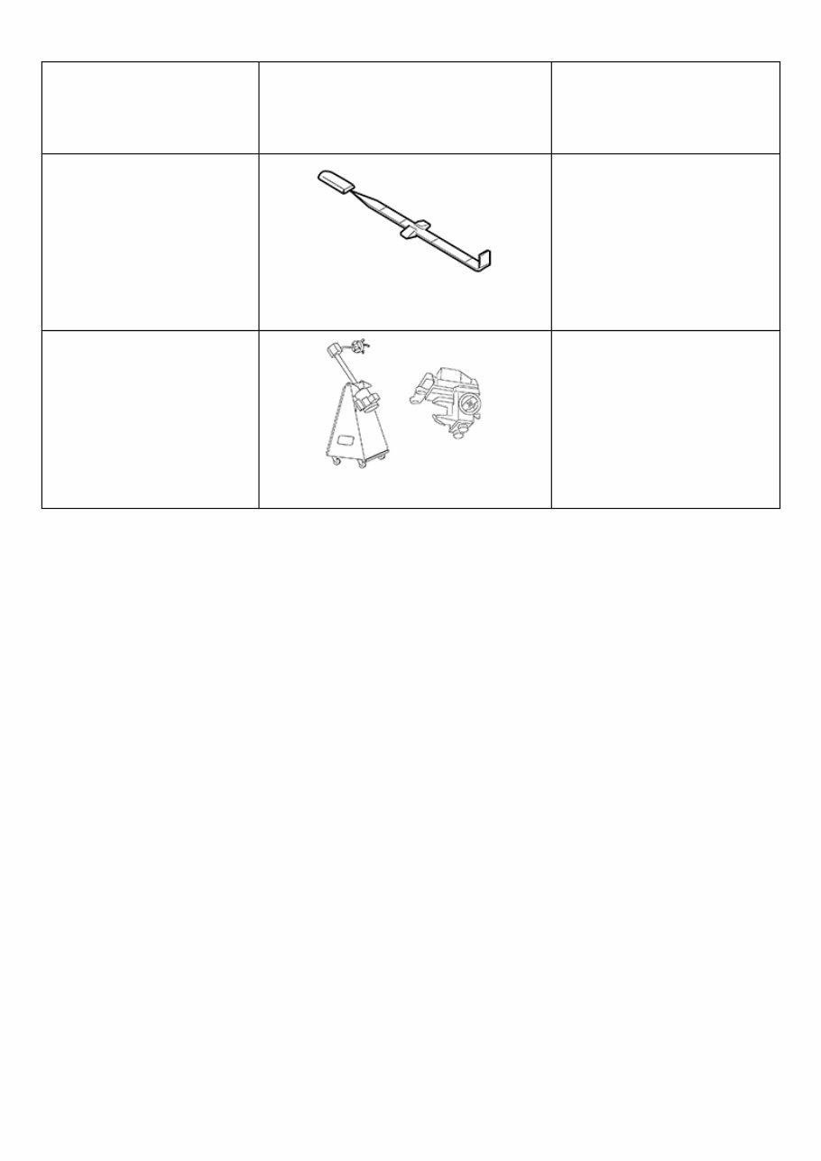
Special Service Tool RDE-001192145 The actual shape of the tools may differ from those illustrated here. Tool number (TechMate No.) Tool name Description — (J-46532) Brake height tool RDE-001192145-01-FIA0227E Measuring brake pedal height 38-PFM92 ( — ) ProCut™ PFM Series Lathe RDE-001192145-02-LFIA0092ZZ Refinishing rotors
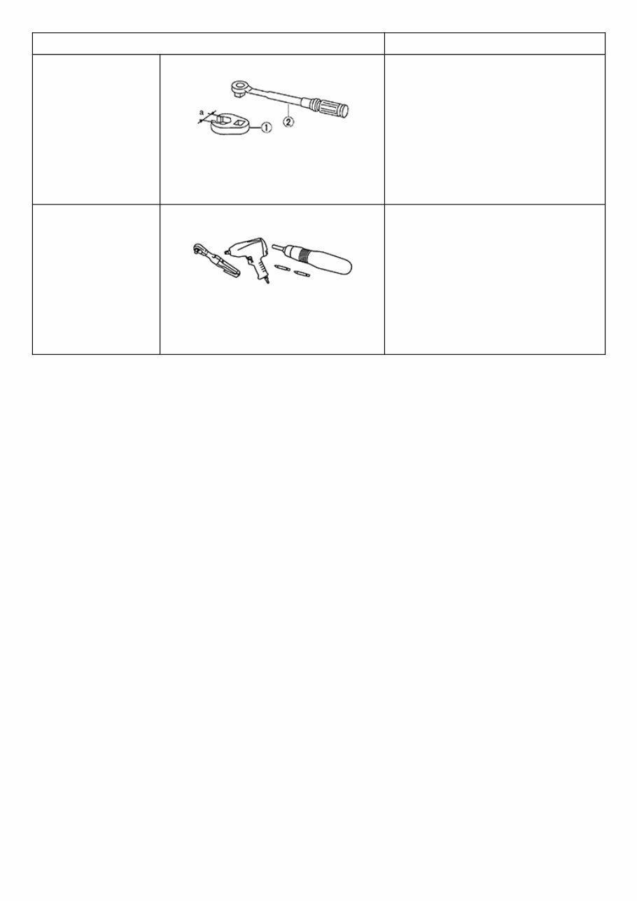
Commercial Service Tool Tool name Description 1. Flare nut crowfoot 2. Torque wrench NISD0000000014654461-01-S- NT360 Tightening brake tube flare nuts a: 10 mm (0.39 in) / 12 mm (0.47 in) Power tool NISD0000000014654461-02- PIIB1407E Loosening nuts, screws and bolts
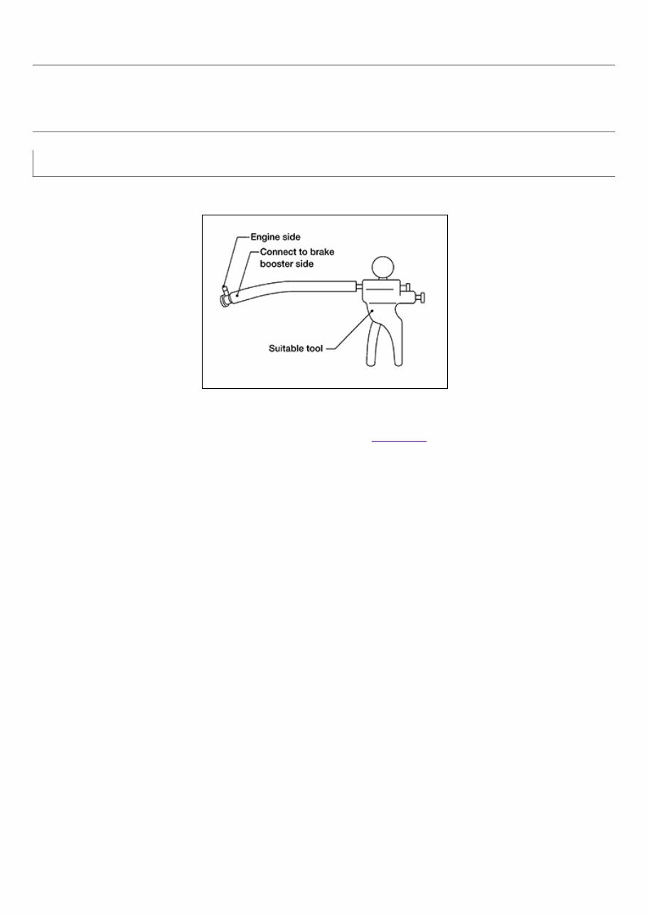
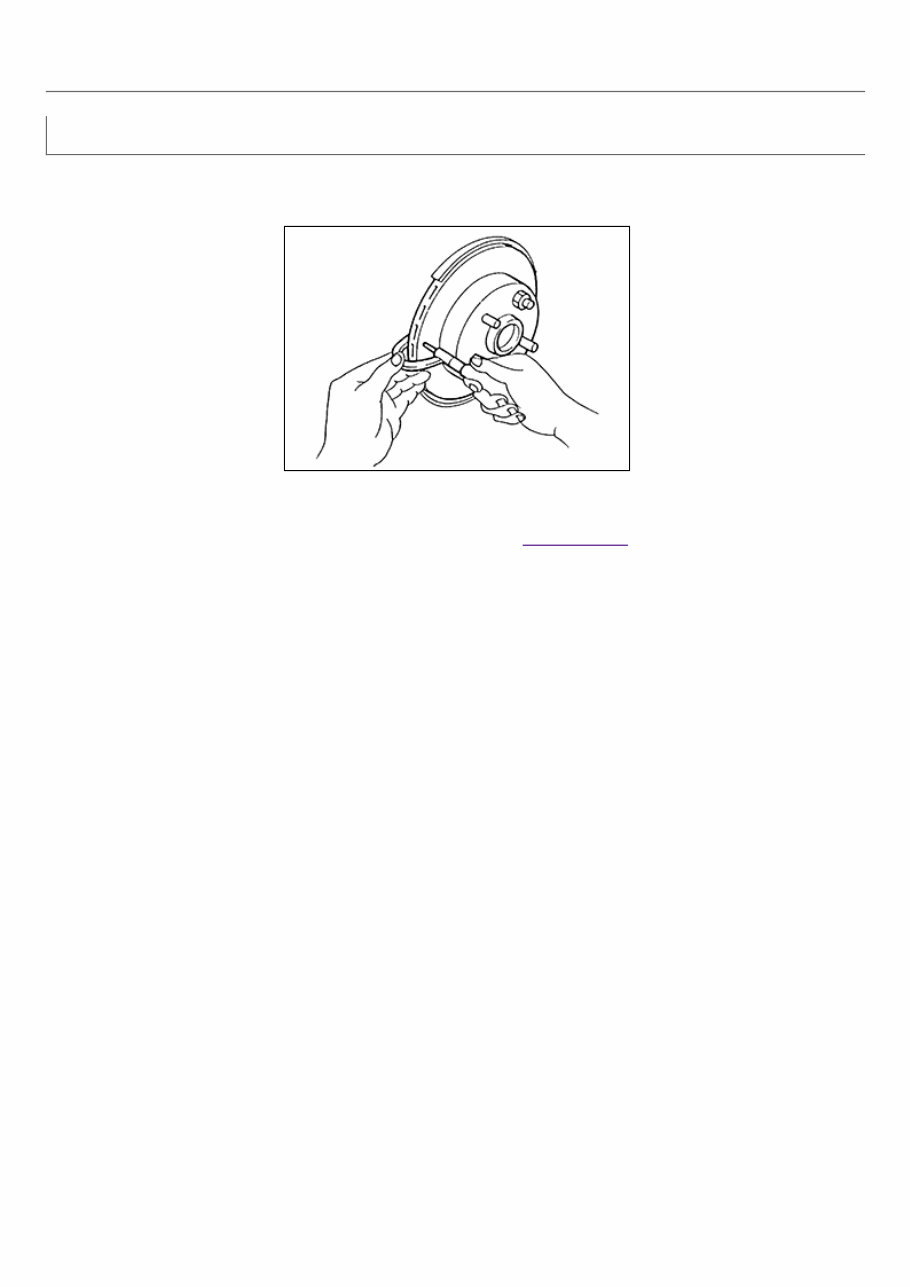
Inspection RDE-000593716 VISUAL INSPECTION Check for improper assembly, damage and deterioration. Replace as necessary. CHECK VALVE INSPECTION Airtightness Inspection Use a suitable tool to test brake booster vacuum check valve. Connect to brake booster side of check valve. RDE-000593716-01-FIA0217E Check valve specification : Refer to Check Valve.
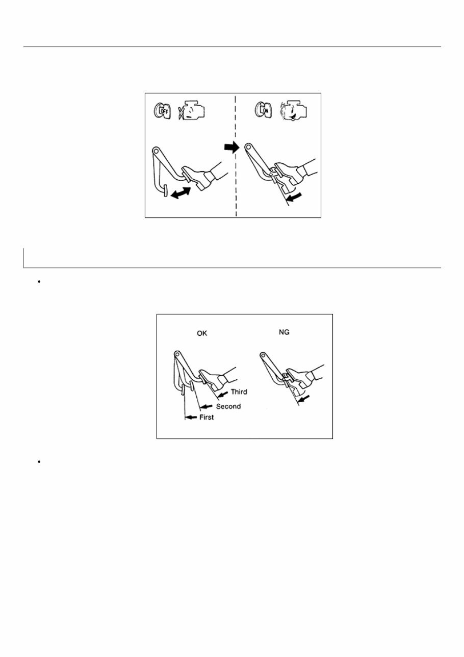
Inspection RDE-000593698 OPERATION With engine stopped, change vacuum to atmospheric pressure by depressing brake pedal several times. Then with brake pedal fully depressed, start engine and when vacuum pressure reaches the standard, make sure that clearance between brake pedal and floor panel decreases. RDE-000593698-01-RA0037D AIR TIGHT Run engine at idle for approximately 1 minute, and stop it after applying vacuum to booster. Depress brake pedal normally to change vacuum to atmospheric pressure. Make sure that distance at intervals of 5 seconds between brake pedal and floor panel gradually increases. RDE-000593698-02-BR365AA Depress brake pedal while engine is running, and stop engine with pedal depressed. The pedal stroke should not change after holding pedal down for 30 seconds.
Inspection RDE-000593696 INSPECTION Uneven Wear Check for uneven wear of the disc brake rotor using a micrometer. Replace the disc brake rotor if the thickness is below the wear limit. RDE-000593696-01-BR020B Thickness variation (measured at 8 positions) : Refer to Rear Disc Brake.
Inspection RDE-000593694 INSPECTION Uneven Wear Check for uneven wear of the disc brake rotor using a micrometer. Replace the disc brake rotor if the thickness is below the wear limit. RDE-000593694-01-BR020B Thickness variation (measured at 8 positions) : Refer to Front Disc Brake.
Inspection RDE-000594144 INSPECTION AFTER REMOVAL CAUTION: Brake tubes and hoses are important safety parts. Always disassemble the parts and retighten their fittings, if a brake fluid leak is detected. Replace applicable part with a new one, if damaged part is detected. 1. Check brake lines (tubes and hoses) and connections for fluid leaks, damage, twists, deformation, contact with other parts, and loose connections. Replace any parts as necessary. Refer to Hydraulic Circuit. 2. While depressing brake pedal under a force of 785 N (80 kg-f, 177 lb-f) with engine running for approximately 5 seconds, check each part for fluid leaks.
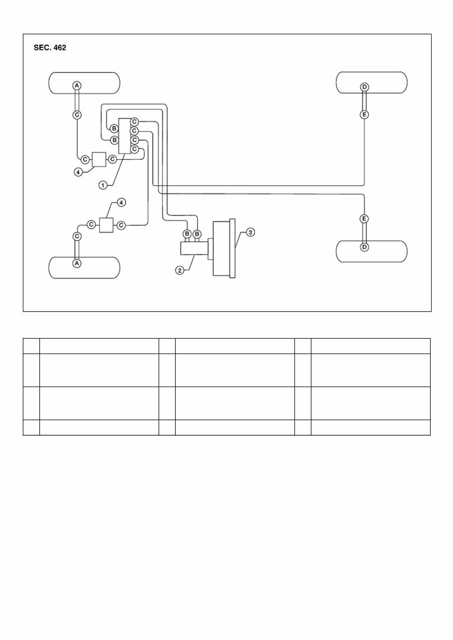
Hydraulic Circuit RDE-001192172 Type 1 and Type 2 - Four Channel Hydraulic System RDE-001192172-01-WFIA0481ZZ 1. Actuator 2. Master cylinder 3. Brake booster 4. Connector A. Union bolt (front caliper) 18.2 N·m (1.9 kg-m, 13 ft-lb) B. Flare nut M12 26.0 N·m (2.7 kg-m, 19 ft-lb) C. Flare nut M10 16.2 N·m (1.7 kg-m, 12 ft-lb) D. Union bolt (rear caliper) 18.2 N·m (1.9 kg-m, 13 ft-lb) E. Flare nut to rear hose 16.2 N·m (1.7 kg-m, 12 ft-lb) Type 1
You're Reading a Preview
What's Included?
Lifetime Access
Fast Download Speeds
Online & Offline Access
Access PDF Contents & Bookmarks
Full Search Facility
Print one or all pages of your manual
$87.99
Loading...
Secure transaction
What's Included?
Lifetime Access
Fast Download Speeds
Online & Offline Access
Access PDF Contents & Bookmarks
Full Search Facility
Print one or all pages of your manual
The 2019 Nissan Frontier Service & Repair Manual is the ultimate resource for any DIY vehicle repairs. It contains all the necessary troubleshooting and replacement procedures recommended by the manufacturer, complete with step-by-step instructions, clear images, and exploded-view illustrations.
With this manual, you can confidently maintain your vehicle's durability and reliability. Regular maintenance is crucial, and the manual provides all the necessary information to keep your vehicle running smoothly.
No more flipping through hundreds of pages or dealing with greasy and torn pages. The electronic version of the manual is easily accessible on various devices, including PCs, Macs, smartphones, and tablets. And if you prefer a physical copy, you can easily print it out.
Don't let vehicle repairs put a dent in your wallet. With the 2019 Nissan Frontier Service & Repair Manual, you can save money on trips to the repair shop and keep your vehicle in top condition. So why wait? Get your hands on this comprehensive manual and take charge of your vehicle's maintenance.