ACC-1 ENGINE C D E F G H I J K L M SECTION ACC A ACC N O P CONTENTS ACCELERATOR CONTROL SYSTEM PRECAUTION .............................................. 2 PRECAUTIONS .................................................. 2 Precaution for Supplemental Restraint System (SRS) "AIR BAG" and "SEAT BELT PRE-TEN- SIONER" .................................................................. 2 UNIT REMOVAL AND INSTALLATION ...... 3 ACCELERATOR CONTROL SYSTEM .............. 3 Component .............................................................. 3 Removal and Installation ......................................... 3 SERVICE DATA AND SPECIFICATIONS (SDS) ............................................................ 5 SERVICE DATA AND SPECIFICATIONS (SDS) .................................................................. 5 Accelerator Control .................................................. 5 Revision: March 2012 2011 Frontier
ACC-2 < PRECAUTION > PRECAUTIONS PRECAUTION PRECAUTIONS Precaution for Supplemental Restraint System (SRS) "AIR BAG" and "SEAT BELT PRE-TENSIONER" INFOID:0000000006250266 The Supplemental Restraint System such as “AIR BAG” and “SEAT BELT PRE-TENSIONER”, used along with a front seat belt, helps to reduce the risk or severity of injury to the driver and front passenger for certain types of collision. This system includes seat belt switch inputs and dual stage front air bag modules. The SRS system uses the seat belt switches to determine the front air bag deployment, and may only deploy one front air bag, depending on the severity of a collision and whether the front occupants are belted or unbelted. Information necessary to service the system safely is included in the SR and SB section of this Service Man- ual. WARNING: • To avoid rendering the SRS inoperative, which could increase the risk of personal injury or death in the event of a collision which would result in air bag inflation, all maintenance must be performed by an authorized NISSAN/INFINITI dealer. • Improper maintenance, including incorrect removal and installation of the SRS, can lead to personal injury caused by unintentional activation of the system. For removal of Spiral Cable and Air Bag Module, see the SR section. • Do not use electrical test equipment on any circuit related to the SRS unless instructed to in this Service Manual. SRS wiring harnesses can be identified by yellow and/or orange harnesses or har- ness connectors. PRECAUTIONS WHEN USING POWER TOOLS (AIR OR ELECTRIC) AND HAMMERS WARNING: • When working near the Airbag Diagnosis Sensor Unit or other Airbag System sensors with the Igni- tion ON or engine running, DO NOT use air or electric power tools or strike near the sensor(s) with a hammer. Heavy vibration could activate the sensor(s) and deploy the air bag(s), possibly causing serious injury. • When using air or electric power tools or hammers, always switch the Ignition OFF, disconnect the battery, and wait at least 3 minutes before performing any service. Revision: March 2012 2011 Frontier
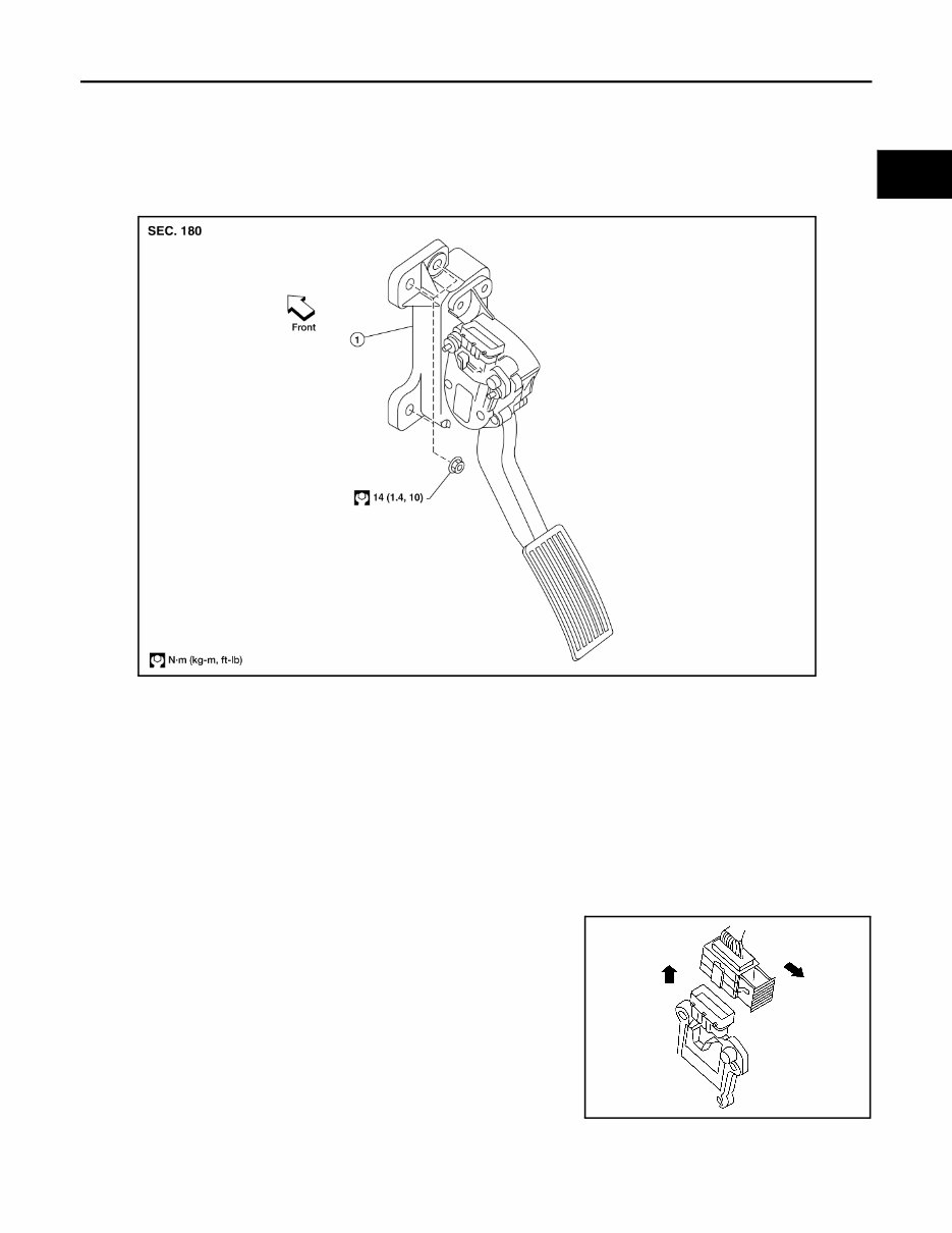
ACCELERATOR CONTROL SYSTEM ACC-3 < UNIT REMOVAL AND INSTALLATION > C D E F G H I J K L M A ACC N P O UNIT REMOVAL AND INSTALLATION ACCELERATOR CONTROL SYSTEM Component INFOID:0000000006250267 CAUTION: • Do not disassemble the accelerator pedal assembly. • Do not remove the accelerator pedal position sensor from the accelerator pedal bracket. • Avoid damage from dropping the accelerator pedal assembly during handling. • Keep the accelerator pedal assembly away from water. Removal and Installation INFOID:0000000006250268 REMOVAL 1. Disconnect the negative battery terminal. 2. Disconnect the accelerator position sensor electrical connector. a. Pull the connector lock back to unlock the connector from the accelerator pedal position sensor as shown. b. Pull up on the connector to disconnect it from the accelerator pedal position sensor as shown. 3. Remove the two upper and one lower accelerator pedal nuts. 4. Remove the accelerator pedal assembly. CAUTION: • Do not disassemble the accelerator pedal assembly. • Do not remove the accelerator pedal position sensor from the accelerator pedal bracket. • Avoid damage from dropping the accelerator pedal assembly during handling. • Keep the accelerator pedal assembly away from water. 1. Accelerator pedal assembly WBIA0594E LBIA0333E Revision: March 2012 2011 Frontier
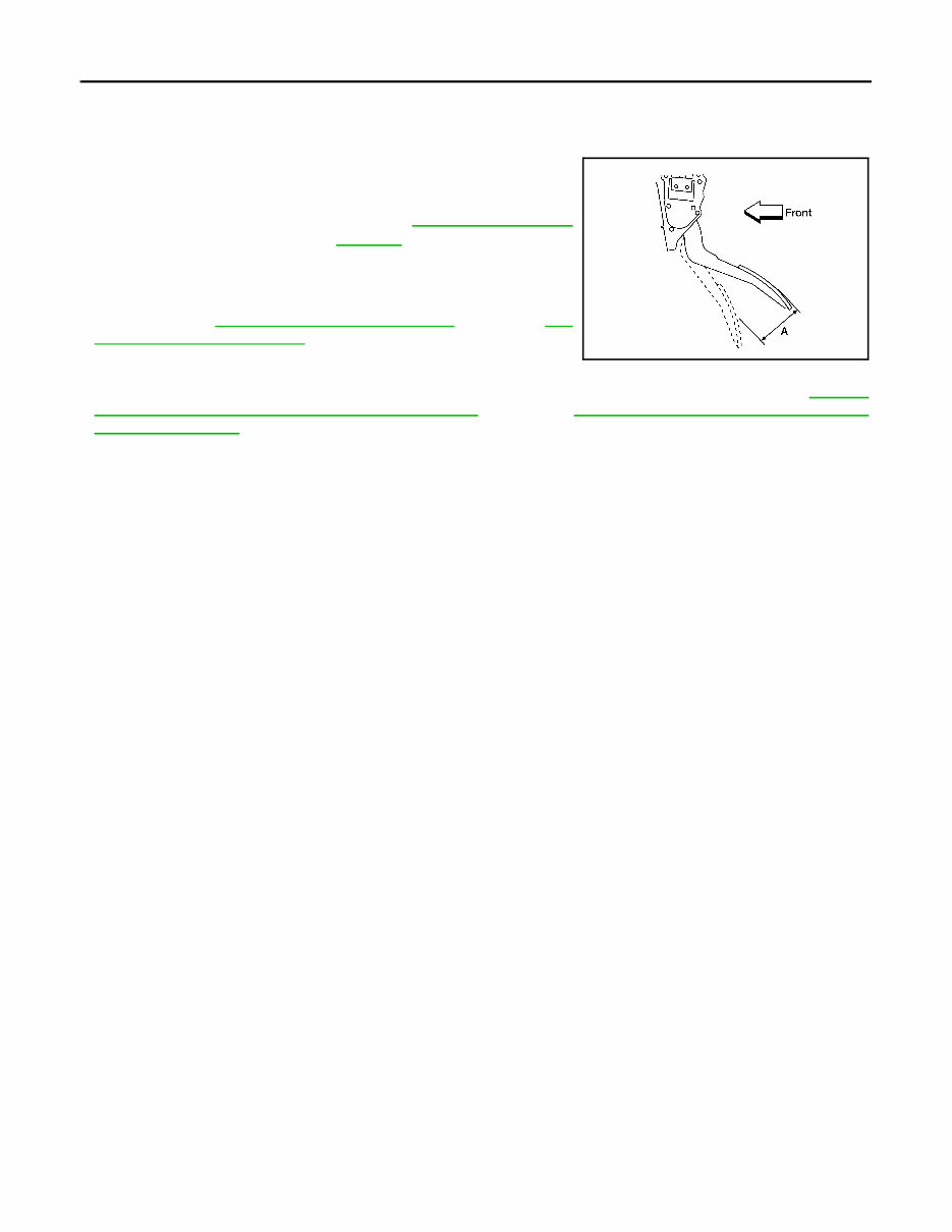
ACC-4 < UNIT REMOVAL AND INSTALLATION > ACCELERATOR CONTROL SYSTEM INSTALLATION Installation is in the reverse order of removal. INSPECTION AFTER INSTALLATION • Check that the accelerator pedal moves smoothly within the speci- fied range. • Check that the accelerator pedal smoothly returns to the original position. • Perform an electrical inspection of the accelerator pedal position sensor. Refer to EC-228, "Component Inspection" (QR25DE), EC- 698, "Component Inspection" (VQ40DE). CAUTION: When the harness connector of the accelerator pedal position sensor is disconnected, perform ″Accelerator Pedal Released Position Learning″. Refer to EC-109, "Accelerator Pedal Released Position Learning" (QR25DE), EC-561, "Accelerator Pedal Released Position Learning" (VQ40DE). Accelerator pedal - total pedal applied stroke (A) : Refer to ACC-5, "Accelerator Control" . LBIA0434E Revision: March 2012 2011 Frontier
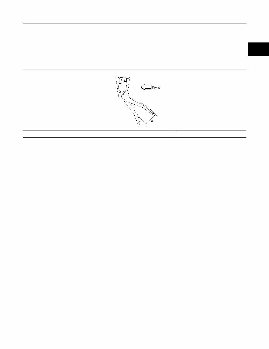
SERVICE DATA AND SPECIFICATIONS (SDS) ACC-5 < SERVICE DATA AND SPECIFICATIONS (SDS) C D E F G H I J K L M A ACC N P O SERVICE DATA AND SPECIFICATIONS (SDS) SERVICE DATA AND SPECIFICATIONS (SDS) Accelerator Control INFOID:0000000006250269 ACCELERATOR PEDAL Unit: mm (in) Accelerator pedal - total pedal applied stroke (A) 48 (1.89) LBIA0434E Revision: March 2012 2011 Frontier
The 2011 Nissan Frontier Service & Repair Manual is the ultimate guide for any DIY enthusiast looking to maintain or repair their vehicle. This comprehensive manual contains all the necessary troubleshooting and replacement procedures recommended by the manufacturer, making it an essential tool for keeping your vehicle in top condition.
With step-by-step instructions, clear images, and exploded-view illustrations, this manual makes fixing problems on your Nissan Frontier a breeze. You no longer have to spend hours flipping through multiple pages to find specific information, as everything you need is easily accessible in one place.
Whether you prefer a digital or physical copy, this manual is compatible with various electronic devices, including PCs, Mac computers, smartphones, and tablets. And with the convenience of being able to search, screenshot, and bookmark pages, it is a much more efficient option than a traditional bound manual.
Regular maintenance is crucial for any vehicle, and this service & repair manual will help you ensure the longevity of your Nissan Frontier. By following the manufacturer's recommended procedures, you can save on costly repairs and increase your vehicle's reliability. So why wait? Get your hands on the 2011 Nissan Frontier Service & Repair Manual today and take control of your vehicle's maintenance needs.