ACC-1 ENGINE C D E F G H I J K L M SECTION ACC A ACC N O P CONTENTS ACCELERATOR CONTROL SYSTEM PRECAUTION .............................................. 2 PRECAUTIONS .................................................. 2 Precaution for Supplemental Restraint System (SRS) "AIR BAG" and "SEAT BELT PRE-TEN- SIONER" .................................................................. 2 REMOVAL AND INSTALLATION ............... 3 ACCELERATOR CONTROL SYSTEM .............. 3 Component .............................................................. 3 Removal and Installation ......................................... 3 SERVICE DATA AND SPECIFICATIONS (SDS) ............................................................ 5 SERVICE DATA AND SPECIFICATIONS (SDS) .................................................................. 5 Accelerator Control .................................................. 5
ACC-2 < PRECAUTION > PRECAUTIONS PRECAUTION PRECAUTIONS Precaution for Supplemental Restraint System (SRS) "AIR BAG" and "SEAT BELT PRE-TENSIONER" INFOID:0000000005530131 The Supplemental Restraint System such as “AIR BAG” and “SEAT BELT PRE-TENSIONER”, used along with a front seat belt, helps to reduce the risk or severity of injury to the driver and front passenger for certain types of collision. This system includes seat belt switch inputs and dual stage front air bag modules. The SRS system uses the seat belt switches to determine the front air bag deployment, and may only deploy one front air bag, depending on the severity of a collision and whether the front occupants are belted or unbelted. Information necessary to service the system safely is included in the SR and SB section of this Service Man- ual. WARNING: • To avoid rendering the SRS inoperative, which could increase the risk of personal injury or death in the event of a collision which would result in air bag inflation, all maintenance must be performed by an authorized NISSAN/INFINITI dealer. • Improper maintenance, including incorrect removal and installation of the SRS, can lead to personal injury caused by unintentional activation of the system. For removal of Spiral Cable and Air Bag Module, see the SR section. • Do not use electrical test equipment on any circuit related to the SRS unless instructed to in this Service Manual. SRS wiring harnesses can be identified by yellow and/or orange harnesses or har- ness connectors. PRECAUTIONS WHEN USING POWER TOOLS (AIR OR ELECTRIC) AND HAMMERS WARNING: • When working near the Airbag Diagnosis Sensor Unit or other Airbag System sensors with the Igni- tion ON or engine running, DO NOT use air or electric power tools or strike near the sensor(s) with a hammer. Heavy vibration could activate the sensor(s) and deploy the air bag(s), possibly causing serious injury. • When using air or electric power tools or hammers, always switch the Ignition OFF, disconnect the battery, and wait at least 3 minutes before performing any service.
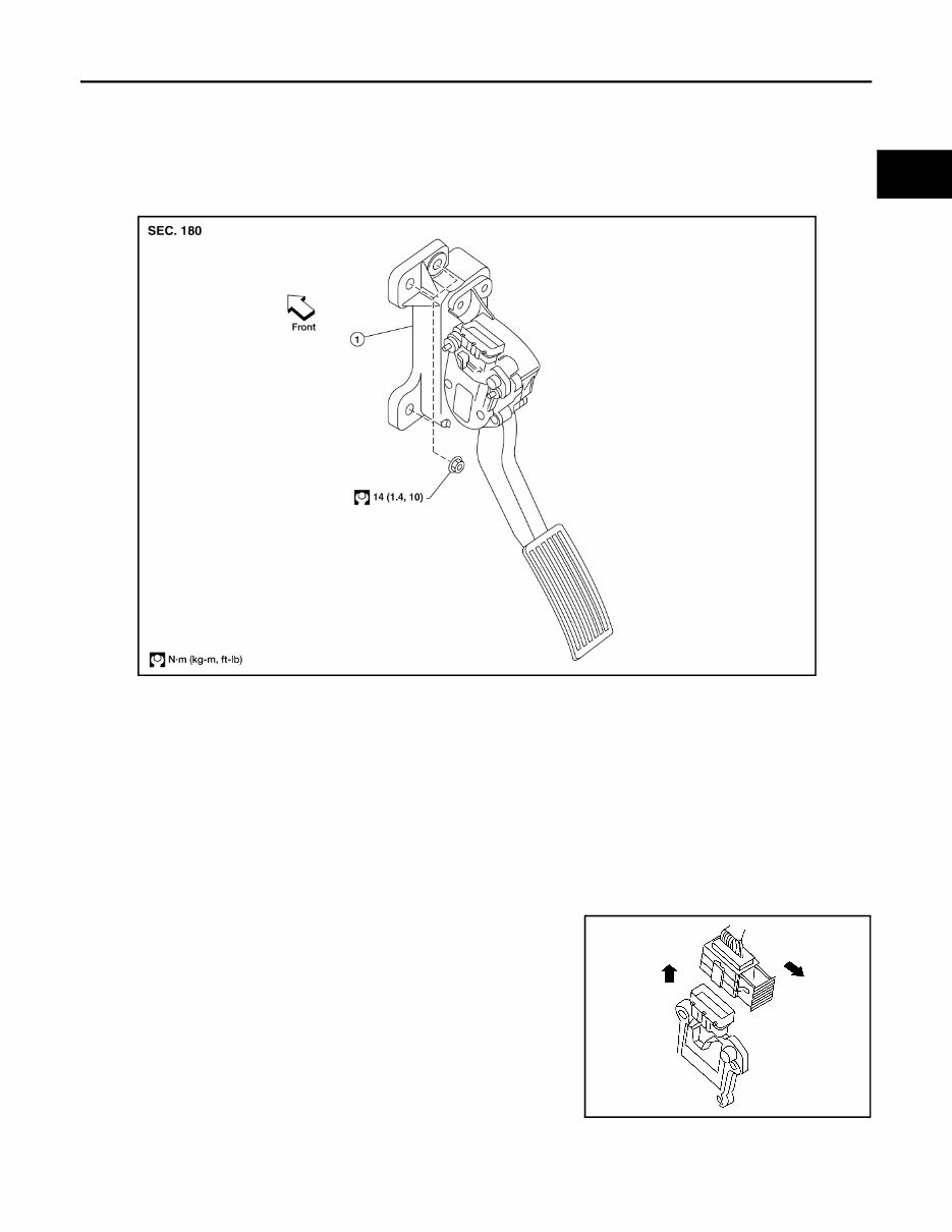
ACCELERATOR CONTROL SYSTEM ACC-3 < REMOVAL AND INSTALLATION > C D E F G H I J K L M A ACC N P O REMOVAL AND INSTALLATION ACCELERATOR CONTROL SYSTEM Component INFOID:0000000005273015 CAUTION: • Do not disassemble the accelerator pedal assembly. • Do not remove the accelerator pedal position sensor from the accelerator pedal bracket. • Avoid damage from dropping the accelerator pedal assembly during handling. • Keep the accelerator pedal assembly away from water. Removal and Installation INFOID:0000000005273016 REMOVAL 1. Disconnect the negative battery terminal. 2. Disconnect the accelerator position sensor electrical connector. a. Pull the connector lock back to unlock the connector from the accelerator pedal position sensor as shown. b. Pull up on the connector to disconnect it from the accelerator pedal position sensor as shown. 3. Remove the two upper and one lower accelerator pedal nuts. 4. Remove the accelerator pedal assembly. CAUTION: • Do not disassemble the accelerator pedal assembly. • Do not remove the accelerator pedal position sensor from the accelerator pedal bracket. • Avoid damage from dropping the accelerator pedal assembly during handling. • Keep the accelerator pedal assembly away from water. 1. Accelerator pedal assembly WBIA0594E LBIA0333E
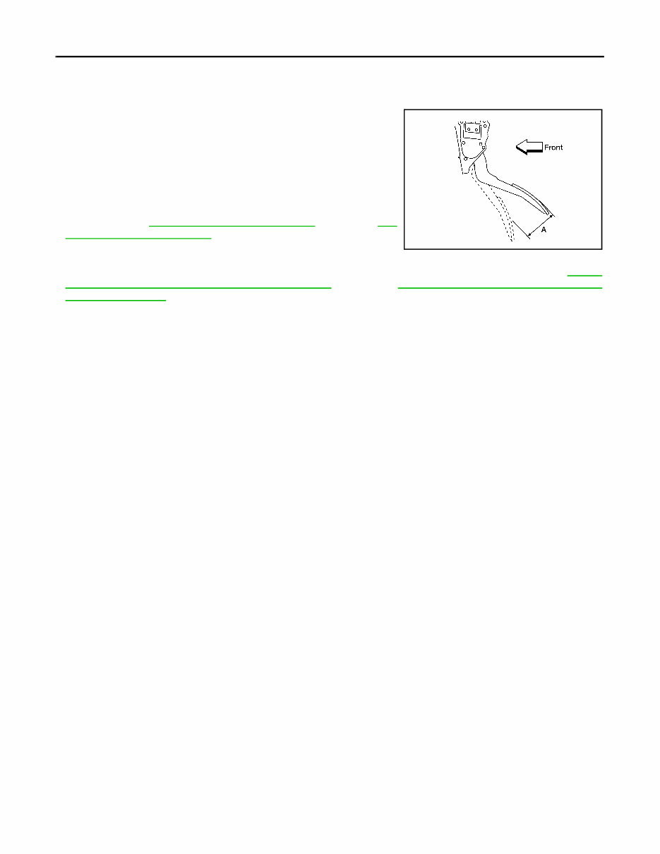
ACC-4 < REMOVAL AND INSTALLATION > ACCELERATOR CONTROL SYSTEM INSTALLATION Installation is in the reverse order of removal. INSPECTION AFTER INSTALLATION • Check that the accelerator pedal moves smoothly within the speci- fied range. • Check that the accelerator pedal smoothly returns to the original position. • Perform an electrical inspection of the accelerator pedal position sensor. Refer to EC-187, "Component Inspection" (QR25DE), EC- 656, "Component Inspection" (VQ40DE). CAUTION: When the harness connector of the accelerator pedal position sensor is disconnected, perform ″Accelerator Pedal Released Position Learning″. Refer to EC-24, "Accelerator Pedal Released Position Learning" (QR25DE), EC-473, "Accelerator Pedal Released Position Learning" (VQ40DE). Accelerator pedal - total pedal applied stroke (A) : 48 mm (1.89 in) LBIA0434E
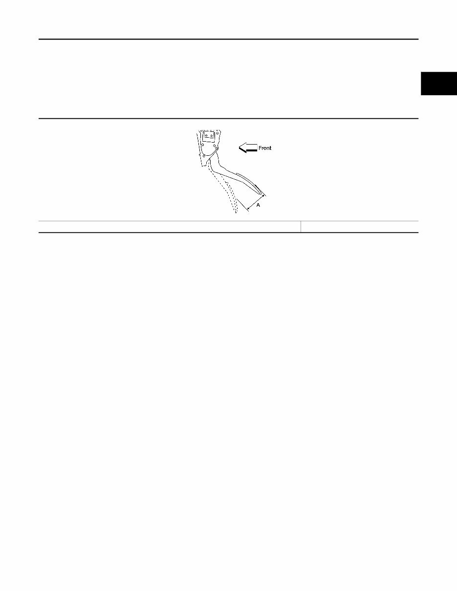
SERVICE DATA AND SPECIFICATIONS (SDS) ACC-5 < SERVICE DATA AND SPECIFICATIONS (SDS) C D E F G H I J K L M A ACC N P O SERVICE DATA AND SPECIFICATIONS (SDS) SERVICE DATA AND SPECIFICATIONS (SDS) Accelerator Control INFOID:0000000005273017 ACCELERATOR PEDAL Unit: mm (in) Accelerator pedal - total pedal applied stroke (A) 48 (1.89) LBIA0434E
AV AV-1 DRIVER INFORMATION & MULTIMEDIA C D E F G H I J K L M B SECTION AV A O P CONTENTS AUDIO, VISUAL & NAVIGATION SYSTEM BASE AUDIO BASIC INSPECTION ................................... 5 DIAGNOSIS AND REPAIR WORKFLOW ......... 5 Work Flow ................................................................ 5 FUNCTION DIAGNOSIS .............................. 7 AUDIO SYSTEM ................................................. 7 System Diagram ....................................................... 7 System Description .................................................. 7 Component Parts Location ....................................... 8 Component Description ............................................ 8 COMPONENT DIAGNOSIS ......................... 9 POWER SUPPLY AND GROUND CIRCUIT ...... 9 AUDIO UNIT ............................................................... 9 AUDIO UNIT : Diagnosis Procedure ........................ 9 FRONT DOOR SPEAKER ................................10 Description ............................................................. 10 Diagnosis Procedure .............................................. 10 FRONT TWEETER ............................................12 Description ............................................................. 12 Diagnosis Procedure .............................................. 12 REAR DOOR SPEAKER ...................................14 Description ............................................................. 14 Diagnosis Procedure .............................................. 14 ECU DIAGNOSIS ........................................ 16 AUDIO UNIT ......................................................16 Reference Value .................................................... 16 Wiring Diagram ...................................................... 18 SYMPTOM DIAGNOSIS ............................. 24 AUDIO SYSTEM ................................................24 Symptom Table ......................................................24 NORMAL OPERATING CONDITION ............... 25 Description ..............................................................25 PRECAUTION ............................................. 26 PRECAUTIONS ................................................. 26 Precaution for Supplemental Restraint System (SRS) "AIR BAG" and "SEAT BELT PRE-TEN- SIONER" ................................................................26 PREPARATION .......................................... 27 PREPARATION ................................................. 27 Commercial Service Tools ......................................27 ON-VEHICLE REPAIR ................................ 28 AUDIO UNIT ...................................................... 28 Removal and Installation ........................................28 FRONT TWEETER ............................................ 29 Removal and Installation ........................................29 FRONT DOOR SPEAKER ................................ 30 Removal and Installation ........................................30 REAR DOOR SPEAKER .................................. 31 Removal and Installation ........................................31 AUDIO ANTENNA ............................................. 32 Location of Audio Antenna System Component .....32 Removal and Installation ........................................32 PREMIUM AUDIO (KING CAB) BASIC INSPECTION .................................. 33 DIAGNOSIS AND REPAIR WORKFLOW ........ 33 Work Flow ...............................................................33 FUNCTION DIAGNOSIS ............................. 35 AUDIO SYSTEM ............................................... 35 Revision: July 2010 2010 Frontier
AV-2 System Diagram .................................................... 35 System Description ................................................ 35 Component Parts Location .................................... 36 Component Description ......................................... 37 HANDS-FREE PHONE SYSTEM ..................... 38 System Diagram .................................................... 38 System Description ................................................ 38 Component Parts Location .................................... 39 Component Description ......................................... 40 DIAGNOSIS SYSTEM (AUDIO UNIT) .............. 41 Component Function Check .................................. 41 DIAGNOSIS SYSTEM (BLUETOOTH CON- TROL UNIT) ...................................................... 42 Diagnosis Description ............................................ 42 Work Flow .............................................................. 42 COMPONENT DIAGNOSIS ....................... 43 POWER SUPPLY AND GROUND CIRCUIT .... 43 AUDIO UNIT ............................................................. 43 AUDIO UNIT : Diagnosis Procedure ..................... 43 SATELLITE RADIO TUNER .................................... 43 SATELLITE RADIO TUNER : Diagnosis Proce- dure ....................................................................... 43 BLUETOOTH CONTROL UNIT ............................... 44 BLUETOOTH CONTROL UNIT : Diagnosis Pro- cedure .................................................................... 44 MICROPHONE ......................................................... 45 MICROPHONE : Diagnosis Procedure .................. 45 FRONT DOOR SPEAKER ................................ 47 Description ............................................................. 47 Diagnosis Procedure ............................................. 47 FRONT TWEETER ........................................... 49 Description ............................................................. 49 Diagnosis Procedure ............................................. 49 REAR DOOR SPEAKER .................................. 51 Description ............................................................. 51 Diagnosis Procedure ............................................. 51 STEERING SWITCH ......................................... 53 Description ............................................................. 53 Diagnosis Procedure ............................................. 53 COMMUNICATION SIGNAL CIRCUIT ............. 55 SATELLITE RADIO TUNER .................................... 55 SATELLITE RADIO TUNER : Description ............. 55 SATELLITE RADIO TUNER : Diagnosis Proce- dure ....................................................................... 55 SOUND SIGNAL CIRCUIT ............................... 58 SATELLITE RADIO TUNER .................................... 58 SATELLITE RADIO TUNER : Description ............. 58 SATELLITE RADIO TUNER : Diagnosis Proce- dure ........................................................................ 58 MICROPHONE SIGNAL CIRCUIT ................... 60 Description ............................................................. 60 Diagnosis Procedure .............................................. 60 ECU DIAGNOSIS ....................................... 62 AUDIO UNIT ..................................................... 62 Reference Value .................................................... 62 Wiring Diagram ...................................................... 65 SATELLITE RADIO TUNER ............................. 76 Reference Value .................................................... 76 BLUETOOTH CONTROL UNIT ........................ 78 Reference Value .................................................... 78 SYMPTOM DIAGNOSIS ............................ 80 AUDIO SYSTEM ............................................... 80 Symptom Table ...................................................... 80 NORMAL OPERATING CONDITION ............... 81 Description ............................................................. 81 PRECAUTION ............................................ 82 PRECAUTIONS ................................................ 82 Precaution for Supplemental Restraint System (SRS) "AIR BAG" and "SEAT BELT PRE-TEN- SIONER" ................................................................ 82 PREPARATION .......................................... 83 PREPARATION ................................................ 83 Commercial Service Tools ..................................... 83 ON-VEHICLE REPAIR ............................... 84 AUDIO UNIT ..................................................... 84 Removal and Installation ........................................ 84 FRONT TWEETER ........................................... 85 Removal and Installation ........................................ 85 FRONT DOOR SPEAKER ................................ 86 Removal and Installation ........................................ 86 REAR DOOR SPEAKER .................................. 87 Removal and Installation ........................................ 87 STEERING SWITCH ......................................... 88 Removal and Installation ........................................ 88 TEL ANTENNA ................................................. 89 Removal and Installation ........................................ 89 BLUETOOTH CONTROL UNIT ........................ 90 Removal and Installation ........................................ 90 MICROPHONE ................................................. 92 Revision: July 2010 2010 Frontier
AV AV-3 C D E F G H I J K L M B A O P Removal and Installation ........................................ 92 AUDIO ANTENNA .............................................93 Location of Antenna ............................................... 93 Removal and Installation ........................................ 93 AUXILIARY INPUT JACK .................................95 Removal and Installation ........................................ 95 SATELLITE RADIO ANTENNA ........................96 Removal and Installation ........................................ 96 SATELLITE RADIO TUNER .............................97 Removal and Installation ........................................ 97 PREMIUM AUDIO (CREW CAB) BASIC INSPECTION .................................. 98 DIAGNOSIS AND REPAIR WORKFLOW ........98 Work Flow .............................................................. 98 FUNCTION DIAGNOSIS ........................... 100 AUDIO SYSTEM .............................................. 100 System Diagram ................................................... 100 System Description .............................................. 100 Component Parts Location ................................... 101 Component Description ........................................ 102 HANDS-FREE PHONE SYSTEM .................... 103 System Diagram ................................................... 103 System Description .............................................. 103 Component Parts Location ................................... 104 Component Description ........................................ 105 DIAGNOSIS SYSTEM (AUDIO UNIT) ............. 106 Component Function Check ................................. 106 DIAGNOSIS SYSTEM (BLUETOOTH CON- TROL UNIT) ..................................................... 107 Diagnosis Description .......................................... 107 Work Flow ............................................................ 107 COMPONENT DIAGNOSIS ...................... 108 POWER SUPPLY AND GROUND CIRCUIT ... 108 AUDIO UNIT ........................................................... 108 AUDIO UNIT : Diagnosis Procedure .................... 108 SATELLITE RADIO TUNER ................................... 108 SATELLITE RADIO TUNER : Diagnosis Proce- dure ...................................................................... 108 AUDIO AMP ............................................................ 109 AUDIO AMP : Diagnosis Procedure ..................... 109 BLUETOOTH CONTROL UNIT .............................. 110 BLUETOOTH CONTROL UNIT : Diagnosis Pro- cedure .................................................................. 110 MICROPHONE ....................................................... 111 MICROPHONE : Diagnosis Procedure ................ 111 FRONT DOOR SPEAKER .............................. 113 Description ............................................................ 113 Diagnosis Procedure ............................................ 113 FRONT TWEETER .......................................... 116 Description ............................................................ 116 Diagnosis Procedure ............................................ 116 REAR DOOR SPEAKER ................................ 119 Description ............................................................ 119 Diagnosis Procedure ............................................ 119 REAR DOOR TWEETER ................................ 122 Description ............................................................ 122 Diagnosis Procedure ............................................ 122 SUBWOOFER ................................................. 125 Description ............................................................ 125 Diagnosis Procedure ............................................ 125 AMP ON SIGNAL CIRCUIT ............................ 128 Description ............................................................ 128 Diagnosis Procedure ............................................ 128 STEERING SWITCH ....................................... 129 Description ............................................................ 129 Diagnosis Procedure ............................................ 129 COMMUNICATION SIGNAL CIRCUIT ........... 131 SATELLITE RADIO TUNER ................................... 131 SATELLITE RADIO TUNER : Description ............ 131 SATELLITE RADIO TUNER : Diagnosis Proce- dure ...................................................................... 131 SOUND SIGNAL CIRCUIT .............................. 134 SATELLITE RADIO TUNER ................................... 134 SATELLITE RADIO TUNER : Description ............ 134 SATELLITE RADIO TUNER : Diagnosis Proce- dure ...................................................................... 134 MICROPHONE SIGNAL CIRCUIT .................. 136 Description ............................................................ 136 Diagnosis Procedure ............................................ 136 ECU DIAGNOSIS ...................................... 138 AUDIO UNIT .................................................... 138 Reference Value ................................................... 138 Wiring Diagram ..................................................... 141 AUDIO AMP .................................................... 155 Reference Value ................................................... 155 SATELLITE RADIO TUNER ........................... 158 Reference Value ................................................... 158 BLUETOOTH CONTROL UNIT ...................... 160 Reference Value ................................................... 160 SYMPTOM DIAGNOSIS ........................... 162 Revision: July 2010 2010 Frontier
AV-4 AUDIO SYSTEM ............................................. 162 Symptom Table .................................................... 162 NORMAL OPERATING CONDITION ............. 163 Description ............................................................ 163 PRECAUTION ........................................... 164 PRECAUTIONS .............................................. 164 Precaution for Supplemental Restraint System (SRS) "AIR BAG" and "SEAT BELT PRE-TEN- SIONER" ............................................................... 164 PREPARATION ......................................... 165 PREPARATION .............................................. 165 Commercial Service Tools .................................... 165 ON-VEHICLE REPAIR .............................. 166 AUDIO UNIT ................................................... 166 Removal and Installation ...................................... 166 AUDIO AMP .................................................... 167 Removal and Installation ...................................... 167 FRONT TWEETER ......................................... 168 Removal and Installation ...................................... 168 FRONT DOOR SPEAKER .............................. 169 Removal and Installation ...................................... 169 REAR DOOR SPEAKER ................................ 170 Removal and Installation ...................................... 170 REAR DOOR TWEETER ................................. 171 Removal and Installation ...................................... 171 STEERING SWITCH ........................................ 172 Removal and Installation ...................................... 172 SUBWOOFER ................................................. 173 Removal and Installation ...................................... 173 TEL ANTENNA ................................................ 174 Removal and Installation ...................................... 174 BLUETOOTH CONTROL UNIT ....................... 175 Removal and Installation ...................................... 175 MICROPHONE ................................................ 177 Removal and Installation ...................................... 177 AUDIO ANTENNA ........................................... 178 Location of Antenna ............................................. 178 Removal and Installation ...................................... 178 AUXILIARY INPUT JACK ............................... 180 Removal and Installation ...................................... 180 SATELLITE RADIO ANTENNA ...................... 181 Removal and Installation ...................................... 181 SATELLITE RADIO TUNER ............................ 182 Removal and Installation ...................................... 182 Revision: July 2010 2010 Frontier
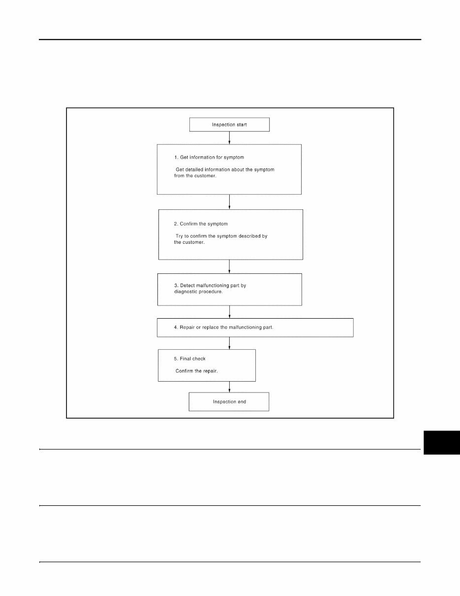
AV DIAGNOSIS AND REPAIR WORKFLOW AV-5 < BASIC INSPECTION > [BASE AUDIO] C D E F G H I J K L M B A O P BASIC INSPECTION DIAGNOSIS AND REPAIR WORKFLOW Work Flow INFOID:0000000005274856 OVERALL SEQUENCE DETAILED FLOW 1.GET INFORMATION FOR SYMPTOM Get detailed information from the customer about the symptom (the condition and the environment when the incident/malfunction occurred). >> GO TO 2 2.CONFIRM THE SYMPTOM Try to confirm the symptom described by the customer. Verify relation between the symptom and the condition when the symptom is detected. >> GO TO 3 3.DETECT MALFUNCTIONING PART BY DIAGNOSTIC PROCEDURE Inspect according to Diagnostic Procedure of the system. ALNIA0182GB Revision: July 2010 2010 Frontier
The 2010 Nissan Frontier Service & Repair Manual is an essential tool for any vehicle owner who wants to take a hands-on approach to fixing problems and maintaining their vehicle. This repair manual contains all the necessary troubleshooting and replacement procedures recommended by the manufacturer, presented in a user-friendly format with step-by-step instructions, clear images, and exploded-view illustrations.
While the Nissan Frontier is known for its durability, regular maintenance is still necessary to ensure its longevity. With this service & repair manual, owners can confidently handle any necessary repairs and replacements, saving both time and money. By following the manufacturer's recommended procedures, owners can increase the reliability of their vehicle and avoid frequent visits to the repair shop.
Gone are the days of flipping through countless pages or dealing with oily, ripped, or lost pages. This manual can be easily carried around, searched, bookmarked, and even printed for those who prefer a physical copy. Plus, it is compatible with various electronic devices, including PCs, Macs, smartphones, and tablets.
With the 2010 Nissan Frontier Service & Repair Manual, owners can trust that they have all the necessary information at their fingertips to properly maintain and repair their vehicle, ensuring its optimal performance for years to come.
Manual Features:
Step-by-step instructions for troubleshooting and replacements
Clear images and exploded-view illustrations
Compatibility with electronic devices
Printable option available
Printable: Yes
Language: English
Compatibility: Pretty much any electronic device, including PC and Mac computers, Android and Apple smartphones and tablets, etc.