HAC-1 VENTILATION, HEATER & AIR CONDITIONER C D E F G H J K L M SECTION HAC A B HAC N O P CONTENTS HEATER & AIR CONDITIONING CONTROL SYSTEM MANUAL AIR CONDITIONER BASIC INSPECTION ................................... 3 DIAGNOSIS AND REPAIR WORKFLOW ......... 3 How to Perform Trouble Diagnosis For Quick And Accurate Repair ....................................................... 3 INSPECTION AND ADJUSTMENT .................... 4 Operational Check ................................................... 4 FUNCTION DIAGNOSIS .............................. 6 FUNCTION INFORMATION ............................... 6 Component Part Location ........................................ 6 Symptom Table ........................................................ 8 REFRIGERATION SYSTEM .............................. 9 Refrigerant Cycle ..................................................... 9 Refrigerant System Protection ................................. 9 MANUAL AIR CONDITIONER SYSTEM ..........10 Control System Diagram ........................................ 10 Control System Description .................................... 10 Discharge Air Flow ................................................. 12 Switches And Their Control Function ..................... 12 DIAGNOSIS SYSTEM (BCM) ...........................14 CONSULT-III Function (BCM - COMMON ITEM) .... 14 CONSULT-III Data Monitor .................................... 14 COMPONENT DIAGNOSIS ........................ 16 MODE DOOR MOTOR ......................................16 System Description ................................................ 16 Mode Door Motor Component Function Check ...... 16 Mode Door Motor Diagnosis Procedure ................. 17 AIR MIX DOOR MOTOR ...................................20 System Description ................................................ 20 Air Mix Door Motor Component Function Check .... 21 Air Mix Door Motor Diagnosis Procedure ............... 22 INTAKE DOOR MOTOR ................................... 24 System Description .................................................24 Intake Door Motor Component Function Check .....24 Intake Door Motor Diagnosis Procedure ................25 BLOWER MOTOR ............................................ 27 System Description .................................................27 Front Blower Motor Component Function Check ....27 Front Blower Motor Diagnosis Procedure ...............28 Front Blower Motor Component Inspection ............32 MAGNET CLUTCH ........................................... 34 System Description .................................................34 Magnet Clutch Component Function Check ...........34 Magnet Clutch Diagnosis Procedure ......................34 INTAKE SENSOR ............................................. 39 System Description .................................................39 Intake Sensor Diagnosis Procedure .......................39 Intake Sensor Component Inspection ....................40 POWER SUPPLY AND GROUND CIRCUIT FOR CONTROLLER ......................................... 41 Component Description ..........................................41 Front Air Control Component Function Check ........41 Front Air Control Power and Ground Diagnosis Procedure ...............................................................42 ECU DIAGNOSIS ........................................ 43 AIR CONDITIONER CONTROL ........................ 43 System Description .................................................43 System Operation ...................................................43 Front Air Control Terminals Reference Values .......44 Wiring Diagram - Air Conditioner Control - Manual ....46 Wiring Diagram - Heater Control ............................53 SYMPTOM DIAGNOSIS ............................. 57 AIR CONDITIONER CONTROL ........................ 57 Symptom Matrix Chart ..........................................57
HAC-2 INSUFFICIENT COOLING ................................ 58 Component Function Check .................................. 58 Performance Test Diagnoses ................................ 59 Performance Chart ................................................ 61 Test Reading ......................................................... 62 Trouble Diagnoses for Unusual Pressure .............. 63 INSUFFICIENT HEATING ................................ 67 Component Function Check .................................. 67 NOISE ............................................................... 69 Component Function Check .................................. 69 PRECAUTION ............................................ 71 PRECAUTIONS ................................................ 71 Supplemental Restraint System (SRS) "AIR BAG" and "SEAT BELT PRE-TENSIONER" ................... 71 Working with HFC-134a (R-134a) .......................... 71 Precaution for Service Equipment ......................... 72
DIAGNOSIS AND REPAIR WORKFLOW HAC-3 < BASIC INSPECTION > [MANUAL AIR CONDITIONER] C D E F G H J K L M A B HAC N O P BASIC INSPECTION DIAGNOSIS AND REPAIR WORKFLOW How to Perform Trouble Diagnosis For Quick And Accurate Repair INFOID:0000000003289095 WORK FLOW 1.LISTEN TO CUSTOMER COMPLAINT Listen to customer complaint. Get detailed information about the conditions and environment when the symp- tom occurs. >> GO TO 2 2.CHECK FOR SERVICE BULLETINS Check for any service bulletins. >> GO TO 3. 3.VERIFY THE SYMPTOM WITH OPERATIONAL CHECK Verify the symptom with operational check. Refer to HAC-4, " Operational Check " . Can a symptom be duplicated? YES >> Go to trouble diagnosis. Refer to HAC-57, " Symptom Matrix Chart " NO >> System OK.
HAC-4 < BASIC INSPECTION > [MANUAL AIR CONDITIONER] INSPECTION AND ADJUSTMENT INSPECTION AND ADJUSTMENT Operational Check INFOID:0000000003289096 The purpose of the operational check is to confirm that the system operates properly. CHECKING BLOWER 1. Turn blower control dial clockwise. Blower should operate on low speed. 2. Turn the blower control dial again, and continue checking each blower speed until all speeds are checked. 3. Leave blower on speed 4. If NG, go to trouble diagnosis procedure for HAC-28, " Front Blower Motor Diagnosis Procedure " . If OK, continue with next check. CHECKING DISCHARGE AIR 1. Turn the mode switch to each position. 2. Confirm that discharge air comes out according to the air distribution table. Refer to HAC-12, " Discharge Air Flow " . Mode door position is checked in the next step. If NG, go to trouble diagnosis procedure for HAC-17, " Mode Door Motor Diagnosis Procedure " . If OK, continue with next check. NOTE: Confirm that the A/C compressor clutch is engaged (sound or visual inspection) and intake door position is at fresh when the DEF ( ) or D/F ( ) is selected. CHECKING RECIRCULATION 1. Press recirculation ( ) switch one time. Recirculation indicator should illuminate. 2. Press recirculation ( ) switch one more time. Recirculation indicator should go off. 3. Listen for intake door position change (blower sound should change slightly). If NG, go to trouble diagnosis procedure for HAC-25, " Intake Door Motor Diagnosis Procedure " . If OK, continue with next check. NOTE: Confirm that the compressor clutch is engaged (sound or visual inspection) and intake door position is at fresh when the DEF or D/F is selected. CHECKING TEMPERATURE DECREASE 1. Rotate temperature control dial counterclockwise. 2. Check for cold air at appropriate discharge air outlets. If NG, listen for sound of air mix door motor operation if OK, go to trouble diagnosis procedure for HAC-58, " Component Function Check " . If air mix door motor appears to be malfunctioning, go to HAC-21, " Air Mix Door Motor Component Function Check " . If OK, continue with next check. CHECKING TEMPERATURE INCREASE 1. Rotate temperature control dial clockwise. 2. Check for hot air at appropriate discharge air outlets. If NG, listen for sound of air mix door motor operation. If OK, go to trouble diagnosis procedure for HAC-67, " Component Function Check " . If air mix door motor (front) appears to be malfunctioning, go to HAC-21, " Air Mix Door Motor Component Function Check " . If OK, continue with next check. CHECK A/C SWITCH (IF EQUIPPED) 1. Press A/C switch with the blower switch ON. 2. A/C switch indicator will turn ON. • Confirm that the compressor clutch engages (sound or visual inspection). Conditions : Engine running and at normal operating temperature
INSPECTION AND ADJUSTMENT HAC-5 < BASIC INSPECTION > [MANUAL AIR CONDITIONER] C D E F G H J K L M A B HAC N O P If NG, go to trouble diagnosis procedure for HAC-34, " Magnet Clutch Diagnosis Procedure " . If OK, continue with next check.
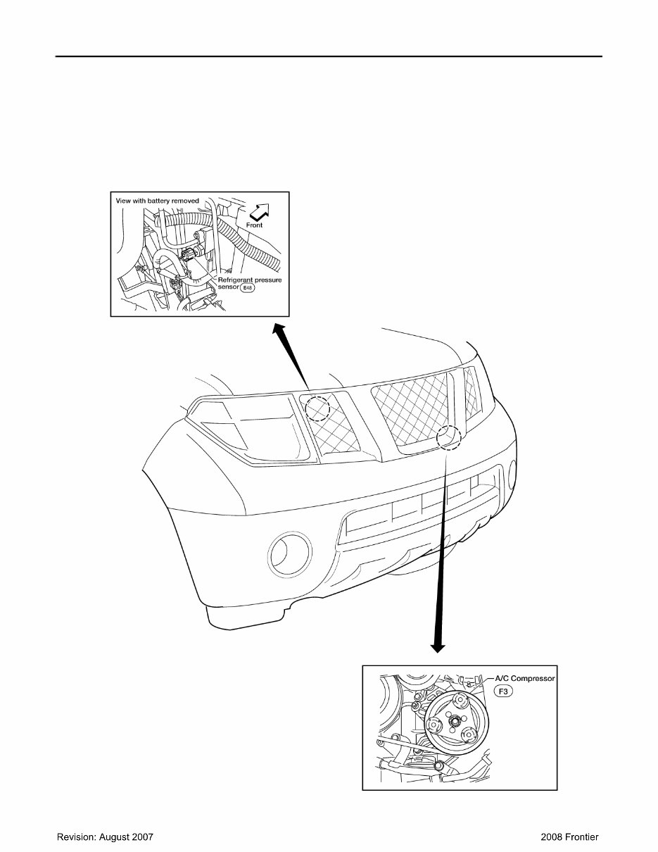
HAC-6 < FUNCTION DIAGNOSIS > [MANUAL AIR CONDITIONER] FUNCTION INFORMATION FUNCTION DIAGNOSIS FUNCTION INFORMATION Component Part Location INFOID:0000000003289097 ENGINE COMPARTMENT WJIA1489E
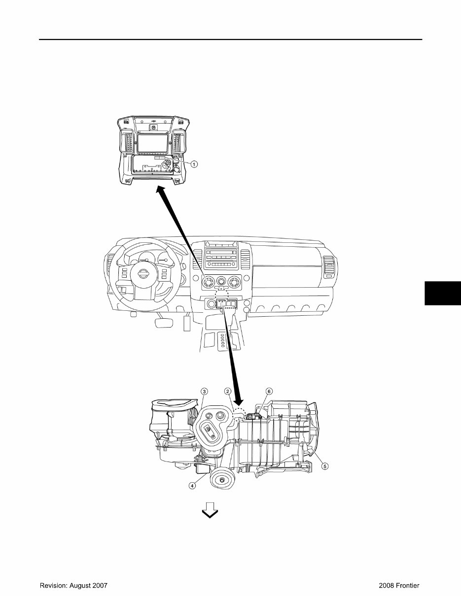
FUNCTION INFORMATION HAC-7 < FUNCTION DIAGNOSIS > [MANUAL AIR CONDITIONER] C D E F G H J K L M A B HAC N O P PASSENGER COMPARTMENT ⇒ :Front 1. Front air control M49 2. Intake sensor M146 AWIIA0724ZZ
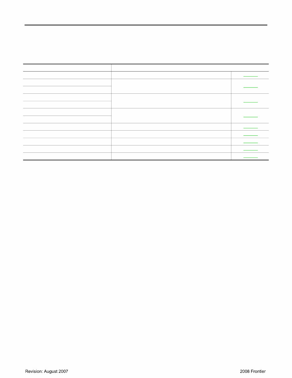
HAC-8 < FUNCTION DIAGNOSIS > [MANUAL AIR CONDITIONER] FUNCTION INFORMATION Symptom Table INFOID:0000000003289098 3. Intake door motor M58 4. Front blower motor resistor M122 5. Mode door motor M142 6. Air mix door motor M147 Symptom Reference Page A/C system does not come on. Go to Trouble Diagnosis Procedure for A/C System. HAC-41 Air outlet does not change. Go to Trouble Diagnosis Procedure for Mode Door Motor. HAC-16 Mode door motor is malfunctioning. Discharge air temperature does not change. Go to Trouble Diagnosis Procedure for Air Mix Door Motor. HAC-21 Air mix door motor is malfunctioning. Intake door does not change. Go to Trouble Diagnosis Procedure for Intake Door Motor. HAC-24 Intake door motor is malfunctioning. Front blower motor operation is malfunctioning. Go to Trouble Diagnosis Procedure for Front Blower Motor. HAC-27 Magnet clutch does not engage. Go to Trouble Diagnosis Procedure for Magnet Clutch. HAC-34 Insufficient cooling Go to Trouble Diagnosis Procedure for Insufficient Cooling. HAC-58 Insufficient heating Go to Trouble Diagnosis Procedure for Insufficient Heating. HAC-67 Noise Go to Trouble Diagnosis Procedure for Noise. HAC-69
REFRIGERATION SYSTEM HAC-9 < FUNCTION DIAGNOSIS > [MANUAL AIR CONDITIONER] C D E F G H J K L M A B HAC N O P REFRIGERATION SYSTEM Refrigerant Cycle INFOID:0000000003289099 Refer to HA-16, " Refrigerant Cycle " . Refrigerant System Protection INFOID:0000000003289100 Refer to HA-16, " Refrigerant System Protection " .
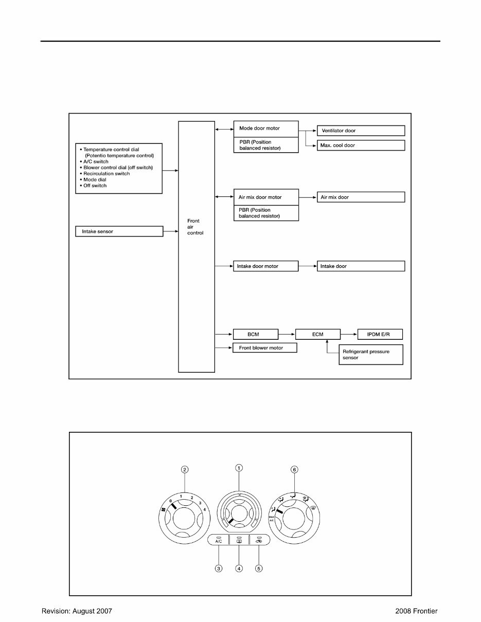
HAC-10 < FUNCTION DIAGNOSIS > [MANUAL AIR CONDITIONER] MANUAL AIR CONDITIONER SYSTEM MANUAL AIR CONDITIONER SYSTEM Control System Diagram INFOID:0000000003289101 CONTROL SYSTEM The control system consists of input sensors, switches, the front air control (microcomputer) and outputs. The relationship of these components is shown in the figure below: Control System Description INFOID:0000000003289102 CONTROL OPERATION Front air control AWIIA0730GB WJIA1510E
Introducing the 2009 Nissan Frontier Service & Repair Manual :
Model 1: 2009 Nissan Frontier
This is designed to provide comprehensive service and repair information for the 2009 Nissan Frontier model. It is a valuable tool for professional mechanics, as well as DIY enthusiasts who prefer to take care of their vehicle maintenance and repairs themselves.
With this , you will have access to detailed step-by-step instructions, diagrams, illustrations, and troubleshooting guides. It covers a wide range of topics, including engine, transmission, electrical systems, suspension, brakes, and more.
Whether you need to perform routine maintenance tasks or address specific repairs, this manual will guide you through the process. It is user-friendly and easy to navigate, making it suitable for both experienced technicians and beginners.
Save time and money by avoiding unnecessary trips to the mechanic. With the 2009 Nissan Frontier Service & Repair Manual , you will have all the information you need to keep your vehicle running smoothly and efficiently.