ACC-1 ENGINE C D E F G H I J K L M SECTION ACC A ACC N O P CONTENTS ACCELERATOR CONTROL SYSTEM PRECAUTION .............................................. 2 PRECAUTIONS .................................................. 2 Precaution for Supplemental Restraint System (SRS) "AIR BAG" and "SEAT BELT PRE-TEN- SIONER" .................................................................. 2 REMOVAL AND INSTALLATION ............... 3 ACCELERATOR CONTROL SYSTEM .............. 3 Component .............................................................. 3 Removal and Installation ......................................... 3 SERVICE DATA AND SPECIFICATIONS (SDS) ............................................................ 5 SERVICE DATA AND SPECIFICATIONS (SDS) .................................................................. 5 Accelerator Control .................................................. 5
ACC-2 < PRECAUTION > PRECAUTIONS PRECAUTION PRECAUTIONS Precaution for Supplemental Restraint System (SRS) "AIR BAG" and "SEAT BELT PRE-TENSIONER" INFOID:0000000003220463 The Supplemental Restraint System such as “AIR BAG” and “SEAT BELT PRE-TENSIONER”, used along with a front seat belt, helps to reduce the risk or severity of injury to the driver and front passenger for certain types of collision. This system includes seat belt switch inputs and dual stage front air bag modules. The SRS system uses the seat belt switches to determine the front air bag deployment, and may only deploy one front air bag, depending on the severity of a collision and whether the front occupants are belted or unbelted. Information necessary to service the system safely is included in the SR and SB section of this Service Man- ual. WARNING: • To avoid rendering the SRS inoperative, which could increase the risk of personal injury or death in the event of a collision which would result in air bag inflation, all maintenance must be performed by an authorized NISSAN/INFINITI dealer. • Improper maintenance, including incorrect removal and installation of the SRS, can lead to personal injury caused by unintentional activation of the system. For removal of Spiral Cable and Air Bag Module, see the SR section. • Do not use electrical test equipment on any circuit related to the SRS unless instructed to in this Service Manual. SRS wiring harnesses can be identified by yellow and/or orange harnesses or har- ness connectors.
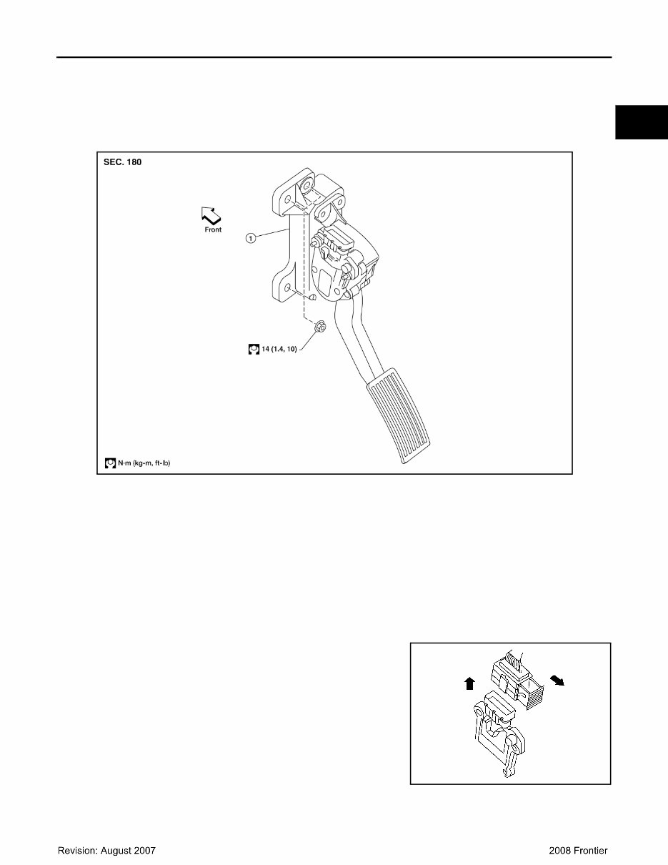
ACCELERATOR CONTROL SYSTEM ACC-3 < REMOVAL AND INSTALLATION > C D E F G H I J K L M A ACC N P O REMOVAL AND INSTALLATION ACCELERATOR CONTROL SYSTEM Component INFOID:0000000003301839 CAUTION: • Do not disassemble the accelerator pedal assembly. • Do not remove the accelerator pedal position sensor from the accelerator pedal bracket. • Avoid damage from dropping the accelerator pedal assembly during handling. • Keep the accelerator pedal assembly away from water. Removal and Installation INFOID:0000000003301838 REMOVAL 1. Disconnect the negative battery terminal. 2. Disconnect the accelerator position sensor electrical connector. a. Pull the connector lock back to unlock the connector from the accelerator pedal position sensor as shown. b. Pull up on the connector to disconnect it from the accelerator pedal position sensor as shown. 3. Remove the two upper and one lower accelerator pedal nuts. 4. Remove the accelerator pedal assembly. CAUTION: • Do not disassemble the accelerator pedal assembly. • Do not remove the accelerator pedal position sensor from the accelerator pedal bracket. • Avoid damage from dropping the accelerator pedal assembly during handling. • Keep the accelerator pedal assembly away from water. 1. Non-adjustable accelerator pedal assembly WBIA0594E LBIA0333E
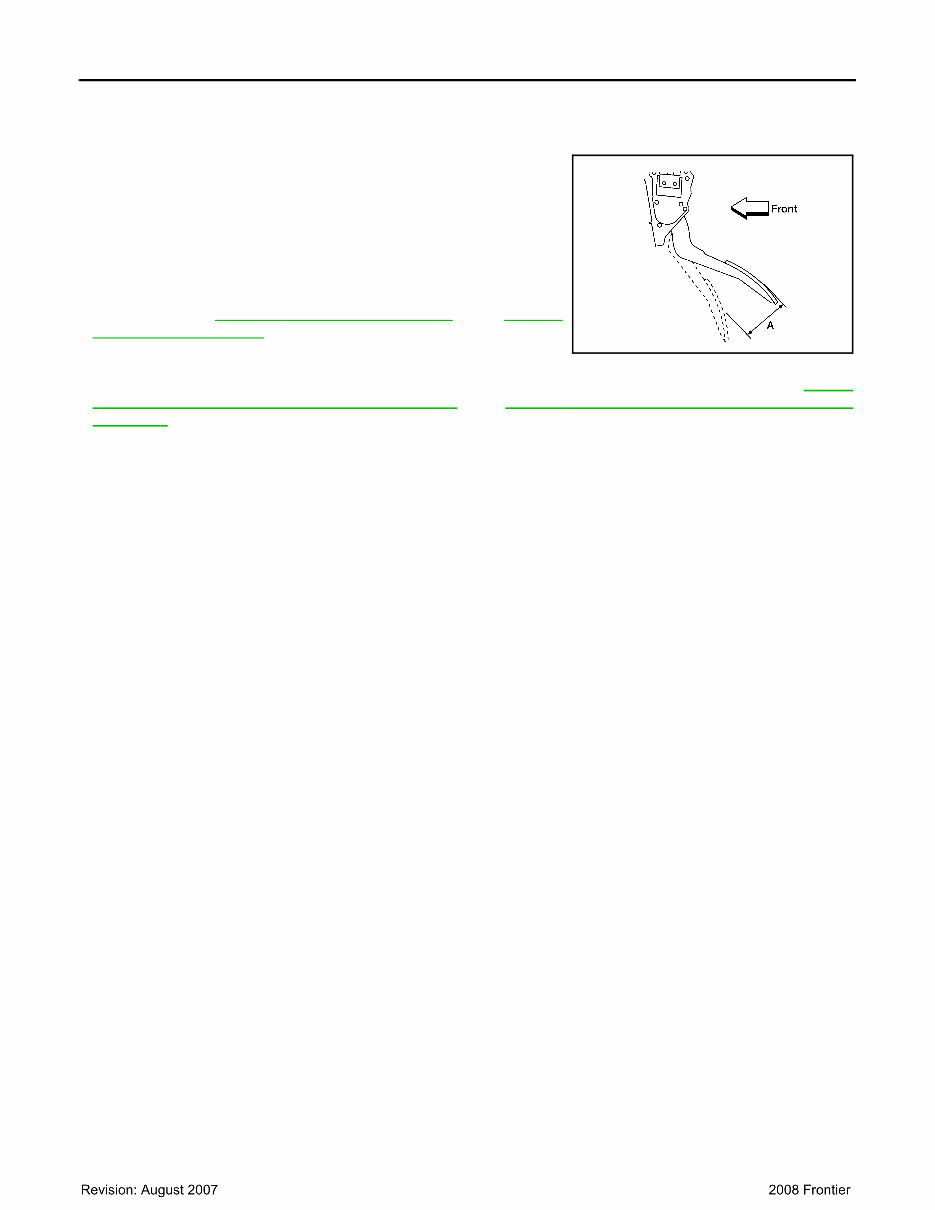
ACC-4 < REMOVAL AND INSTALLATION > ACCELERATOR CONTROL SYSTEM INSTALLATION Installation is in the reverse order of removal. INSPECTION AFTER INSTALLATION • Check that the accelerator pedal moves smoothly within the speci- fied range. • Check that the accelerator pedal smoothly returns to the original position. • Perform an electrical inspection of the accelerator pedal position sensor. Refer to EC-181, " Component Inspection " (QR), EC-638, " Component Inspection " (VQ). CAUTION: When the harness connector of the accelerator pedal position sensor is disconnected, perform ″Accelerator Pedal Released Position Learning″. Refer to EC-24, " Accelerator Pedal Released Position Learning " (QR), EC-464, " Accelerator Pedal Released Position Learning " (VQ). Accelerator pedal - total pedal applied stroke “A” : 48 mm (1.89 in) LBIA0434E
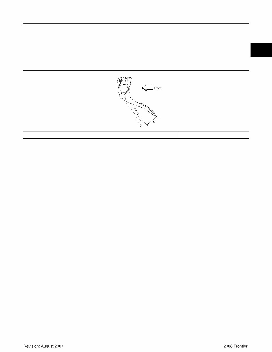
SERVICE DATA AND SPECIFICATIONS (SDS) ACC-5 < SERVICE DATA AND SPECIFICATIONS (SDS) C D E F G H I J K L M A ACC N P O SERVICE DATA AND SPECIFICATIONS (SDS) SERVICE DATA AND SPECIFICATIONS (SDS) Accelerator Control INFOID:0000000003301840 ACCELERATOR PEDAL Unit: mm (in) Accelerator pedal - total pedal applied stroke “A” 48 (1.89) LBIA0434E
This 2008 Nissan Frontier Service & Repair Manual is the ultimate guide for maintaining and repairing your Nissan Frontier. It provides step-by-step instructions and illustrations to help you tackle any repair or service task with confidence.
Complete coverage for all 2008 Nissan Frontier models:
Nissan Frontier XE
Nissan Frontier SE
Nissan Frontier LE
Whether you need to perform routine maintenance, such as changing the oil or replacing brake pads, or tackle more complex repairs, such as engine or transmission overhaul, this manual has you covered. With detailed specifications, diagrams, and troubleshooting tips, you can confidently handle any repair job.
The manual is available in .PDF format and can be easily accessed on your computer or laptop. It is compatible with all operating systems, making it convenient for both home mechanics and professional technicians.
Keep your 2008 Nissan Frontier running smoothly and efficiently with this comprehensive Service & Repair Manual. It's a valuable resource for both professional mechanics and DIY enthusiasts.