2000 Nissan Frontier 33L VG Service & Repair Manual
What's Included?
Lifetime Access
Fast Download Speeds
Offline Viewing
Access Contents & Bookmarks
Full Search Facility
Print one or all pages of your manual
AUTOMATIC TRANSMISSION SECTION AT CONTENTS TROUBLE DIAGNOSIS - INDEX ....................................4 Alphabetical & P No. Index for DTC ...........................4 PRECAUTIONS ...............................................................6 Precautions for Supplemental Restraint System (SRS) ″AIR BAG″ ........................................................6 Precautions for On Board Diagnostic (OBD) System of A/T and Engine...........................................6 Precautions ..................................................................7 Service Notice or Precautions .....................................8 Wiring Diagrams and Trouble Diagnosis .....................9 PREPARATION .............................................................10 Special Service Tools ................................................10 OVERALL SYSTEM ......................................................12 A/T Electrical Parts Location .....................................12 Circuit Diagram ..........................................................13 Cross-sectional View .................................................14 Hydraulic Control Circuit ............................................15 Shift Mechanism ........................................................16 Control System ..........................................................25 Control Mechanism....................................................26 Control Valve .............................................................31 ON BOARD DIAGNOSTIC SYSTEM DESCRIPTION ...............................................................33 Introduction ................................................................33 OBD-II Function for A/T System................................33 One or Two Trip Detection Logic of OBD-II ..............33 OBD-II Diagnostic Trouble Code (DTC) ....................33 Malfunction Indicator Lamp (MIL) ..............................37 CONSULT ..................................................................37 Diagnostic Procedure Without CONSULT .................46 TROUBLE DIAGNOSIS - INTRODUCTION..................53 Introduction ................................................................53 Work Flow ..................................................................57 TROUBLE DIAGNOSIS - BASIC INSPECTION ...........59 A/T Fluid Check .........................................................59 Stall Test ....................................................................59 Line Pressure Test .....................................................62 Road Test ...................................................................63 TROUBLE DIAGNOSIS - GENERAL DESCRIPTION ...............................................................81 Symptom Chart ..........................................................81 TCM Terminals and Reference Value........................92 TROUBLE DIAGNOSIS FOR POWER SUPPLY..........96 Wiring Diagram - AT - MAIN......................................96 DTC P0705 PARK/NEUTRAL POSITION SWITCH .....99 Description .................................................................99 Wiring Diagram - AT - PNP/SW...............................101 Diagnostic Procedure ..............................................102 Component Inspection .............................................104 DTC P0710 A/T FLUID TEMPERATURE SENSOR CIRCUIT .......................................................................105 Description ...............................................................105 Wiring Diagram - AT - FTS ......................................107 Diagnostic Procedure ..............................................108 Component Inspection ............................................. 110 DTC P0720 VEHICLE SPEED SENSOR.A/T (REVOLUTION SENSOR) ........................................... 111 Description ............................................................... 111 Wiring Diagram - AT - VSSA/T ................................ 113 Diagnostic Procedure .............................................. 114 Component Inspection ............................................. 115 DTC P0725 ENGINE SPEED SIGNAL ....................... 116 Description ............................................................... 116 Wiring Diagram - AT - ENGSS ................................ 118 Diagnostic Procedure .............................................. 119 DTC P0731 IMPROPER SHIFTING TO 1ST GEAR POSITION ....................................................................121 Description ...............................................................121 Wiring Diagram - AT - 1ST ......................................124 Diagnostic Procedure ..............................................125 Component Inspection .............................................126 DTC P0732 IMPROPER SHIFTING TO 2ND GEAR POSITION ....................................................................127 Description ...............................................................127 Wiring Diagram - AT - 2ND......................................130 Diagnostic Procedure ..............................................131 Component Inspection .............................................132 GI MA EM LC EC FE CL MT AT TF PD FA RA BR ST RS BT HA EL IDX
DTC P0733 IMPROPER SHIFTING TO 3RD GEAR POSITION ....................................................................133 Description ...............................................................133 Wiring Diagram - AT - 3RD......................................136 Diagnostic Procedure ..............................................137 Component Inspection .............................................138 DTC P0734 IMPROPER SHIFTING TO 4TH GEAR POSITION ....................................................................139 Description ...............................................................139 Wiring Diagram - AT - 4TH ......................................143 Diagnostic Procedure ..............................................144 Component Inspection .............................................149 DTC P0740 TORQUE CONVERTER CLUTCH SOLENOID VALVE......................................................150 Description ...............................................................150 Wiring Diagram - AT - TCV......................................152 Diagnostic Procedure ..............................................153 Component Inspection .............................................154 DTC P0744 IMPROPER LOCK-UP OPERATION ......155 Description ...............................................................155 Wiring Diagram - AT - TCCSIG ...............................158 Diagnostic Procedure ..............................................159 Component Inspection .............................................164 DTC P0745 LINE PRESSURE SOLENOID VALVE ...165 Description ...............................................................165 Wiring Diagram - AT - LPSV....................................167 Diagnostic Procedure ..............................................168 Component Inspection .............................................169 DTC P0750 SHIFT SOLENOID VALVE A ..................171 Description ...............................................................171 Wiring Diagram - AT - SSV/A ..................................173 Diagnostic Procedure ..............................................174 Component Inspection .............................................175 DTC P0755 SHIFT SOLENOID VALVE B ..................176 Description ...............................................................176 Wiring Diagram - AT - SSV/B ..................................178 Diagnostic Procedure ..............................................179 Component Inspection .............................................180 DTC P1705 THROTTLE POSITION SENSOR ...........181 Description ...............................................................181 Wiring Diagram - AT - TPS ......................................184 Diagnostic Procedure ..............................................185 Component Inspection .............................................189 DTC P1760 OVERRUN CLUTCH SOLENOID VALVE..........................................................................190 Description ...............................................................190 Wiring Diagram - AT - OVRCSV..............................192 Diagnostic Procedure ..............................................193 Component Inspection .............................................194 DTC BATT/FLUID TEMP SEN (A/T FLUID TEMP SENSOR CIRCUIT AND TCM POWER SOURCE) ....195 Description ...............................................................195 Wiring Diagram - AT - BA/FTS ................................197 Diagnostic Procedure ..............................................198 Component Inspection .............................................200 VEHICLE SPEED SENSOR.MTR................................201 Description ...............................................................201 Wiring Diagram - AT - VSSMTR..............................203 Diagnostic Procedure ..............................................204 DTC CONTROL UNIT (RAM), CONTROL UNIT (ROM) ...........................................................................205 Description ...............................................................205 Diagnostic Procedure ..............................................206 DTC CONTROL UNIT (EEPROM) ..............................207 Description ...............................................................207 Diagnostic Procedure ..............................................208 TROUBLE DIAGNOSES FOR SYMPTOMS ...............209 Wiring Diagram - AT - NONDTC .............................209 1. O/D OFF Indicator Lamp Does Not Come On....212 2. Engine Cannot Be Started In P and N Position..214 3. In ″P″ Position, Vehicle Moves Forward Or Backward When Pushed .........................................215 4. In N Position, Vehicle Moves ..............................216 5. Large Shock. N -> R Position .............................218 6. Vehicle Does Not Creep Backward In R Position ....................................................................220 7. Vehicle Does Not Creep Forward In D, 2 Or 1 Position ....................................................................223 8. Vehicle Cannot Be Started From D 1 ...................226 9. A/T Does Not Shift: D 1 -> D 2 Or Does Not Kickdown: D 4 -> D 2 ..................................................229 10. A/T Does Not Shift: D 2 -> D 3 .............................232 11. A/T Does Not Shift: D 3 -> D 4 .............................235 12. A/T Does Not Perform Lock-up .........................238 13. A/T Does Not Hold Lock-up Condition ..............240 14. Lock-up Is Not Released ...................................242 15. Engine Speed Does Not Return To Idle (Light Braking D 4 -> D 3 ).....................................................243 16. Vehicle Does Not Start From D 1 .......................245 17. A/T Does Not Shift: D 4 -> D 3 , When Overdrive Control Switch ON -> OFF .....................246 18. A/T Does Not Shift: D 3 -> 2 2 , When Selector Lever D -> 2 Position ..............................................247 19. A/T Does Not Shift: 2 2 -> 1 1 , When Selector Lever 2 -> 1 Position ...............................................248 20. Vehicle Does Not Decelerate By Engine Brake........................................................................249 21. TCM Self-diagnosis Does Not Activate (PNP, Overdrive Control and Throttle Position Switches Circuit Checks) ........................................................249 A/T SHIFT LOCK SYSTEM.........................................257 Description ...............................................................257 Wiring Diagram - SHIFT - ........................................258 Diagnostic Procedure ..............................................259 CONTENTS (Cont’d) AT-2
Component Check ...................................................261 KEY INTERLOCK CABLE ..........................................262 Components.............................................................262 Removal ...................................................................262 Installation ................................................................263 ON-VEHICLE SERVICE ..............................................264 Control Valve Assembly and Accumulators .............264 Revolution Sensor Replacement .............................265 Rear Oil Seal Replacement .....................................265 Parking Components Inspection..............................265 Park/Neutral Position (PNP) Switch Adjustment .....265 Manual Control Linkage Adjustment........................266 REMOVAL AND INSTALLATION ...............................267 Removal ...................................................................267 Installation ................................................................268 OVERHAUL .................................................................270 Components.............................................................270 Oil Channel ..............................................................272 Locations of Needle Bearings, Thrust Washers and Snap Rings .......................................................273 DISASSEMBLY............................................................274 REPAIR FOR COMPONENT PARTS .........................285 Oil Pump ..................................................................285 Control Valve Assembly ...........................................289 Control Valve Upper Body .......................................295 Control Valve Lower Body .......................................300 Reverse Clutch ........................................................302 High Clutch ..............................................................306 Forward and Overrun Clutches ...............................308 Low & Reverse Brake..............................................312 Forward Clutch Drum Assembly ..............................316 Rear Internal Gear and Forward Clutch Hub ..........318 Band Servo Piston Assembly ..................................321 Parking Pawl Components ......................................325 ASSEMBLY..................................................................327 Assembly (1) ............................................................327 Adjustment ...............................................................334 Assembly (2) ............................................................337 SERVICE DATA AND SPECIFICATIONS (SDS) .......344 General Specifications .............................................344 Shift Schedule..........................................................344 Stall Revolution ........................................................344 Line Pressure...........................................................344 Return Springs .........................................................345 Accumulator O-ring ..................................................346 Clutches and Brakes ...............................................346 Oil Pump and Low One-way Clutch ........................348 Total End Play..........................................................348 Reverse Clutch Drum End Play ..............................349 Removal and Installation .........................................349 GI MA EM LC EC FE CL MT AT TF PD FA RA BR ST RS BT HA EL IDX CONTENTS (Cont’d) AT-3
Alphabetical & P No. Index for DTC NEAT0179 ALPHABETICAL INDEX FOR DTC NEAT0179S01 Items (CONSULT screen terms) DTC Reference page ECM*1 CONSULT GST*2 A/T 1ST GR FNCTN 1103 P0731 AT-121 A/T 2ND GR FNCTN 1104 P0732 AT-127 A/T 3RD GR FNCTN 1105 P0733 AT-133 A/T 4TH GR FNCTN 1106 P0734 AT-139 A/T TCC S/V FNCTN 1107 P0744 AT-155 ATF TEMP SEN/CIRC 1208 P0710 AT-105 ENGINE SPEED SIG 1207 P0725 AT-116 L/PRESS SOL/CIRC 1205 P0745 AT-165 O/R CLTCH SOL/CIRC 1203 P1760 AT-190 PNP SW/CIRC 1101 P0705 AT-99 SFT SOL A/CIRC*3 1108 P0750 AT-171 SFT SOL B/CIRC*3 1201 P0755 AT-176 TP SEN/CIRC A/T*3 1206 P1705 AT-181 TCC SOLENOID/CIRC 1204 P0740 AT-150 VEH SPD SEN/CIR AT*4 1102 P0720 AT-111 *1: In Diagnostic Test Mode II (Self-diagnostic results), these numbers are controlled by NISSAN. *2: These numbers are prescribed by SAE J2012. *3: When the fail-safe operation occurs, the MIL illuminates. *4: The MIL illuminates when both the “Revolution sensor signal” and the “Vehicle speed sensor signal” meet the fail-safe condition at the same time. TROUBLE DIAGNOSIS — INDEX Alphabetical & P No. Index for DTC AT-4
P NO. INDEX FOR DTC =NEAT0179S02 DTC Items (CONSULT screen terms) Reference page CONSULT GST*2 ECM*1 P0705 1101 PNP SW/CIRC AT-99 P0710 1208 ATF TEMP SEN/CIRC AT-105 P0720 1102 VEH SPD SEN/CIR AT*4 AT-111 P0725 1207 ENGINE SPEED SIG AT-116 P0731 1103 A/T 1ST GR FNCTN AT-121 P0732 1104 A/T 2ND GR FNCTN AT-127 P0733 1105 A/T 3RD GR FNCTN AT-133 P0734 1106 A/T 4TH GR FNCTN AT-139 P0740 1204 TCC SOLENOID/CIRC AT-150 P0744 1107 A/T TCC S/V FNCTN AT-155 P0745 1205 L/PRESS SOL/CIRC AT-165 P0750 1108 SFT SOL A/CIRC*3 AT-171 P0755 1201 SFT SOL B/CIRC*3 AT-176 P1705 1206 TP SEN/CIRC A/T*3 AT-181 P1760 1203 O/R CLTCH SOL/CIRC AT-190 *1: In Diagnostic Test Mode II (Self-diagnostic results), these numbers are controlled by NISSAN. *2: These numbers are prescribed by SAE J2012. *3: When the fail-safe operation occurs, the MIL illuminates. *4: The MIL illuminates when both the “Revolution sensor signal” and the “Vehicle speed sensor signal” meet the fail-safe condition at the same time. GI MA EM LC EC FE CL MT AT TF PD FA RA BR ST RS BT HA EL IDX TROUBLE DIAGNOSIS — INDEX Alphabetical & P No. Index for DTC (Cont’d) AT-5
Precautions for Supplemental Restraint System (SRS) “AIR BAG” NEAT0001 The Supplemental Restraint System “AIR BAG”, used along with a seat belt, helps to reduce the risk or severity of injury to the driver and front passenger in a frontal collision. The Supplemental Restraint System consists of air bag modules (located in the center of the steering wheel and on the instrument panel on the passen- ger side), a diagnosis sensor unit, a crash zone sensor, warning lamp, wiring harness and spiral cable. The vehicle is equipped with a passenger air bag deactivation switch. Because no rear seat exists where a rear-facing child restraint can be placed, the switch is designed to turn off the passenger air bag so that a rear-facing child restraint can be used in the front passenger seat. The switch is located in the center of the instrument panel near the ashtray. When the switch is turned to the ON position, the passenger air bag is enabled and could inflate in a frontal collision. When the switch is turned to the OFF position, the passenger air bag is disabled and will not inflate in a frontal collision. A passenger air bag OFF indicator on the instru- ment panel lights up when the passenger air bag is switched OFF. The driver air bag always remains enabled and is not affected by the passenger air bag deactivation switch. Information necessary to service the system safely is included in the RS section of this Service Manual. WARNING: I To avoid rendering the SRS inoperative, which could increase the risk of personal injury or death in the event of a collision which would result in air bag inflation, all maintenance should be per- formed by an authorized NISSAN dealer. I Improper maintenance, including incorrect removal and installation of the SRS, can lead to per- sonal injury caused by unintentional activation of the system. I Do not use electrical test equipment on any circuit related to the SRS unless instructed to in this Service Manual. SRS wiring harnesses are covered with yellow insulation either just before the harness connectors or for the complete harness, for easy identification. I The vehicle is equipped with a passenger air bag deactivation switch which can be operated by the customer. When the air bag is switched OFF, the passenger air bag is disabled and will not inflate in a frontal collision. When the passenger air bag is switched ON, the passenger air bag is enabled and could inflate in a frontal collision. After SRS maintenance or repair, make sure the passenger air bag deactivation switch is in the same position (ON or OFF) as when the vehicle arrived for service. Precautions for On Board Diagnostic (OBD) System of A/T and Engine NEAT0002 The ECM has an on board diagnostic system. It will light up the malfunction indicator lamp (MIL) to warn the driver of a malfunction causing emission deterioration. CAUTION: I Be sure to turn the ignition switch OFF and disconnect the negative battery terminal before any repair or inspection work. The open/short circuit of related switches, sensors, solenoid valves, etc. will cause the MIL to light up. I Be sure to connect and lock the connectors securely after work. A loose (unlocked) connector will cause the MIL to light up due to an open circuit. (Be sure the connector is free from water, grease, dirt, bent terminals, etc.) I Be sure to route and secure the harnesses properly after work. Interference of the harness with a bracket, etc. may cause the MIL to light up due to a short circuit. I Be sure to connect rubber tubes properly after work. A misconnected or disconnected rubber tube may cause the MIL to light up due to a malfunction of the EGR system or fuel injection system, etc. I Be sure to erase the unnecessary malfunction information (repairs completed) from the TCM and ECM before returning the vehicle to the customer. PRECAUTIONS Precautions for Supplemental Restraint System (SRS) “AIR BAG” AT-6
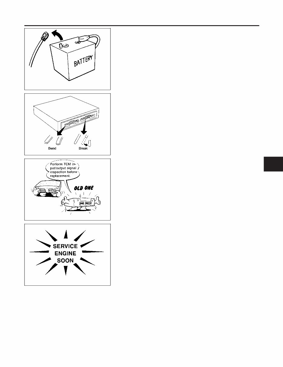
SEF289H Precautions NEAT0003 I Before connecting or disconnecting the TCM harness connector, turn ignition switch OFF and disconnect nega- tive battery terminal. Failure to do so may damage the TCM. Because battery voltage is applied to TCM even if ignition switch is turned off. AAT470A I When connecting or disconnecting pin connectors into or from TCM, take care not to damage pin terminals (bend or break). Make sure that there are not any bends or breaks on TCM pin terminal, when connecting pin connectors. MEF040DA I Before replacing TCM, perform TCM input/output signal inspection and make sure whether TCM functions prop- erly or not. (See page AT-92.) SAT964I I After performing each TROUBLE DIAGNOSIS, perform “DTC (Diagnostic Trouble Code) CONFIRMATION PROCE- DURE”. The DTC should not be displayed in the “DTC CONFIRMA- TION PROCEDURE” if the repair is completed. I Before proceeding with disassembly, thoroughly clean the out- side of the transmission. It is important to prevent the internal parts from becoming contaminated by dirt or other foreign mat- ter. I Disassembly should be done in a clean work area. I Use lint-free cloth or towels for wiping parts clean. Common shop rags can leave fibers that could interfere with the opera- tion of the transmission. I Place disassembled parts in order for easier and proper assembly. I All parts should be carefully cleaned with a general purpose, GI MA EM LC EC FE CL MT AT TF PD FA RA BR ST RS BT HA EL IDX PRECAUTIONS Precautions AT-7
non-flammable solvent before inspection or reassembly. I Gaskets, seals and O-rings should be replaced any time the transmission is disassembled. I It is very important to perform functional tests whenever they are indicated. I The valve body contains precision parts and requires extreme care when parts are removed and serviced. Place disas- sembled valve body parts in order for easier and proper assembly. Care will also prevent springs and small parts from becoming scattered or lost. I Properly installed valves, sleeves, plugs, etc. will slide along bores in valve body under their own weight. I Before assembly, apply a coat of recommended ATF to all parts. Apply petroleum jelly to protect O-rings and seals, or hold bearings and washers in place during assembly. Do not use grease. I Extreme care should be taken to avoid damage to O-rings, seals and gaskets when assembling. I Replace ATF cooler if excessive foreign material is found in oil pan or clogging strainer. Refer to “ATF COOLER SERVICE” (Refer to AT-9). I After overhaul, refill the transmission with new ATF. I When the A/T drain plug is removed, only some of the fluid is drained. Old A/T fluid will remain in torque converter and ATF cooling system. Always follow the procedures under “Changing A/T Fluid” in the MA section when changing A/T fluid. Service Notice or Precautions NEAT0004 FAIL-SAFE NEAT0004S01 The TCM has an electronic Fail-Safe (limp home mode). This allows the vehicle to be driven even if a major electrical input/output device circuit is damaged. Under Fail-Safe, the vehicle always runs in third gear, even with a shift lever position of “1”, “2” or “D”. The customer may complain of sluggish or poor acceleration. When the ignition key is turned “ON” following Fail-Safe operation, O/D OFF indicator lamp blinks for about 8 seconds. (For “TCM SELF-DIAGNOSTIC PROCEDURE (No Tools)”, refer toAT-46.) Fail-Safe may occur without electrical circuit damage if the vehicle is driven under extreme conditions (such as excessive wheel spin followed by sudden braking). To recover normal shift pattern, turn the ignition key “OFF” for 5 seconds, then “ON”. The blinking of the O/D OFF indicator lamp for about 8 seconds will appear only once and be cleared. The customer may resume normal driving conditions. Always follow the “WORK FLOW” (Refer to AT-57). The SELF-DIAGNOSIS results will be as follows: The first SELF-DIAGNOSIS will indicate damage to the vehicle speed sensor or the revolution sensor. During the next SELF-DIAGNOSIS, performed after checking the sensor, no damages will be indicated. TORQUE CONVERTER SERVICE NEAT0004S04 The torque converter should be replaced under any of the following conditions: I External leaks in the hub weld area. I Converter hub is scored or damaged. I Converter pilot is broken, damaged or fits poorly into crankshaft. PRECAUTIONS Precautions (Cont’d) AT-8
I Steel particles are found after flushing the cooler and cooler lines. I Pump is damaged or steel particles are found in the converter. I Vehicle has TCC shudder and/or no TCC apply. Replace only after all hydraulic and electrical diagnoses have been made. (Converter clutch material may be glazed.) I Converter is contaminated with engine coolant containing antifreeze. I Internal failure of stator roller clutch. I Heavy clutch debris due to overheating (blue converter). I Steel particles or clutch lining material found in fluid filter or on magnet when no internal parts in unit are worn or damaged — indicates that lining material came from converter. The torque converter should not be replaced if: I The fluid has an odor, is discolored, and there is no evidence of metal or clutch facing particles. I The threads in one or more of the converter bolt holes are damaged. I Transmission failure did not display evidence of damaged or worn internal parts, steel particles or clutch plate lining material in unit and inside the fluid filter. I Vehicle has been exposed to high mileage (only). The exception may be where the torque converter clutch dampener plate lining has seen excess wear by vehicles operated in heavy and/or constant traffic, such as taxi, delivery or police use. ATF COOLER SERVICE NEAT0004S02 Replace ATF cooler if excessive foreign material is found in oil pan or clogging strainer. Replace radiator lower tank (which includes ATF cooler) with a new one and flush cooler line using cleaning solvent and compressed air. OBD-II SELF-DIAGNOSIS NEAT0004S03 I A/T self-diagnosis is performed by the TCM in combination with the ECM. The results can be read through the blinking pattern of the O/D OFF indicator or the malfunction indicator lamp (MIL). Refer to the table on AT-38 for the indicator used to display each self-diagnostic result. I The self-diagnostic results indicated by the MIL are automatically stored in both the ECM and TCM memories. Always perform the procedure “HOW TO ERASE DTC” on AT-35 to complete the repair and avoid unnecessary blinking of the MIL. I The following self-diagnostic items can be detected using ECM self-diagnostic results mode* only when the O/D OFF indicator lamp does not indicate any malfunctions. - Park/neutral position (PNP) switch - A/T 1st, 2nd, 3rd, or 4th gear function - A/T TCC S/V function (lock-up) *: For details of OBD-II, refer to EC section (“ON BOARD DIAGNOSTIC SYSTEM DESCRIPTION”). I Certain systems and components, especially those related to OBD, may use a new style slide- locking type harness connector. For description and how to disconnect, refer to EL section, “Description”, “HARNESS CONNECTOR”. Wiring Diagrams and Trouble Diagnosis NEAT0005 When you read wiring diagrams, refer to the followings: I “HOW TO READ WIRING DIAGRAMS” in GI section I “POWER SUPPLY ROUTING” for power distribution circuit in EL section When you perform trouble diagnosis, refer to the followings: I “HOW TO FOLLOW TEST GROUP IN TROUBLE DIAGNOSIS” in GI section I “HOW TO PERFORM EFFICIENT DIAGNOSIS FOR AN ELECTRICAL INCIDENT” in GI section GI MA EM LC EC FE CL MT AT TF PD FA RA BR ST RS BT HA EL IDX PRECAUTIONS Service Notice or Precautions (Cont’d) AT-9
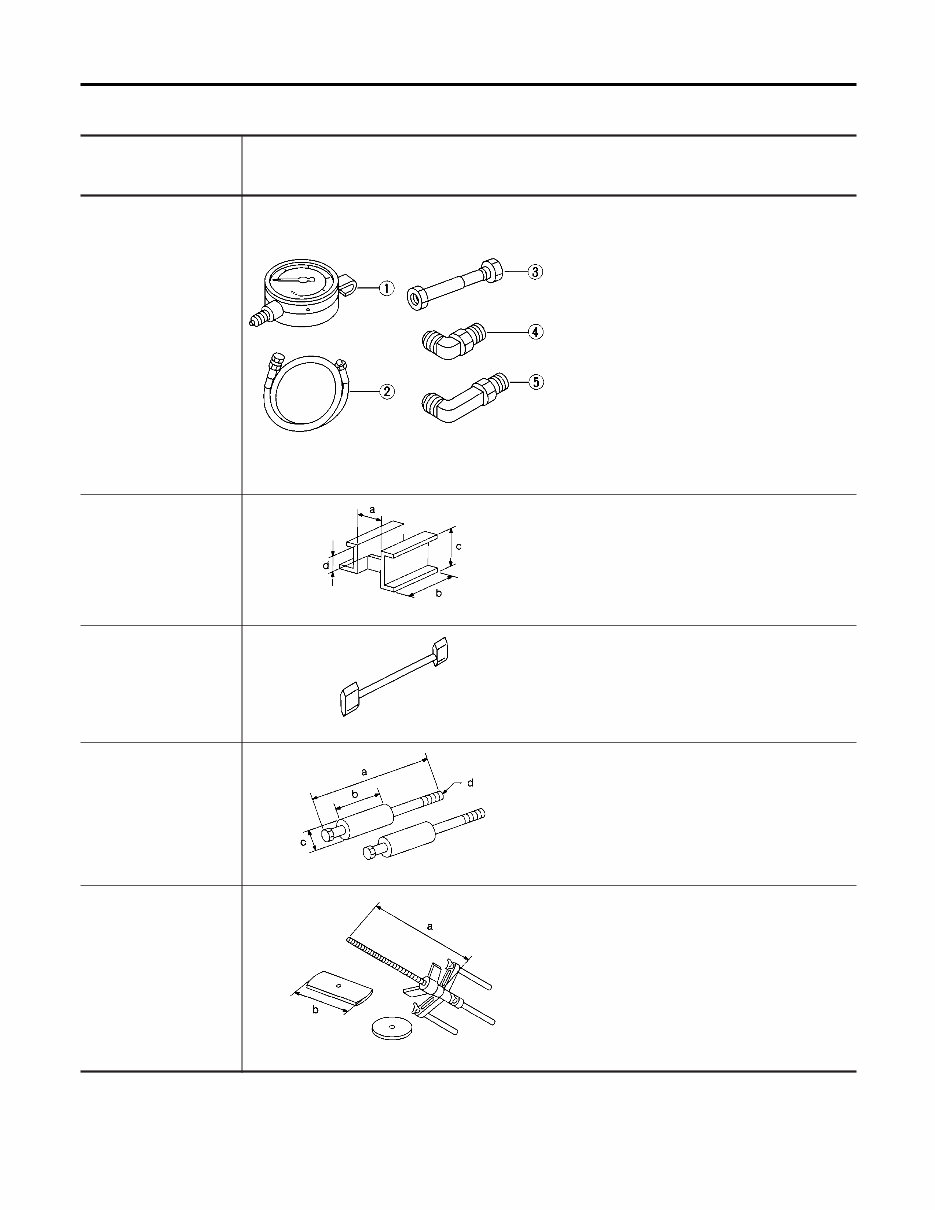
Special Service Tools NEAT0006 The actual shapes of Kent-Moore tools may differ from those of special service tools illustrated here. Tool number (Kent-Moore No.) Tool name Description ST2505S001 (J34301-C) Oil pressure gauge set 1 ST25051001 ( — ) Oil pressure gauge 2 ST25052000 ( — ) Hose 3 ST25053000 ( — ) Joint pipe 4 ST25054000 ( — ) Adapter 5 ST25055000 ( — ) Adapter NT097 Measuring line pressure ST07870000 (J37068) Transmission case stand NT421 Disassembling and assembling A/T a: 182 mm (7.17 in) b: 282 mm (11.10 in) c: 230 mm (9.06 in) d: 100 mm (3.94 in) KV31102100 (J37065) Torque converter one- way clutch check tool NT098 Checking one-way clutch in torque converter ST25850000 (J25721-A) Sliding hammer NT422 Removing oil pump assembly a: 179 mm (7.05 in) b: 70 mm (2.76 in) c: 40 mm (1.57 in) dia. d: M12 x 1.75P KV31102400 (J34285 and J34285-87) Clutch spring compres- sor NT423 Removing and installing clutch return springs a: 320 mm (12.60 in) b: 174 mm (6.85 in) PREPARATION Special Service Tools AT-10
The 2000 Nissan Frontier 3.3L VG Service & Repair Manual (VINs up to 343314) is the perfect guide for any DIY vehicle owner. With step-by-step instructions, clear images, and exploded-view illustrations provided by the manufacturer, this manual makes troubleshooting and replacement procedures a breeze.
Regular maintenance is essential for the durability of your vehicle, and with this manual, you'll have all the necessary information at your fingertips. No more flipping through hundreds of pages or dealing with greasy, torn, or lost pages. You can easily access the manual on any electronic device and even print it out if you prefer a physical copy.
This manual covers all models of the 2000 Nissan Frontier with a 3.3L VG engine and VINs up to 343314. Whether you have a PC or Mac computer, an Android or Apple smartphone or tablet, this manual is compatible with pretty much any electronic device. All you need is Adobe Reader (free) to access the manual.
Don't let vehicle repairs drain your wallet or leave you stranded. With the 2000 Nissan Frontier 3.3L VG Service & Repair Manual, you can save on repairs, increase your vehicle's reliability, and keep the repair shop at bay. Get your copy today and have peace of mind knowing you have all the necessary information to keep your vehicle running smoothly.
Recently Viewed
5,521,897Happy Clients
2,594,462eManuals
1,120,453Trusted Sellers
15Years in Business
Price:
Actual Price:
2000 Nissan Frontier 33L VG Service & Repair Manual