HAC-1 VENTILATION, HEATER & AIR CONDITIONER C D E F G H J K L M SECTION HAC A B HAC N O P CONTENTS HEATER & AIR CONDITIONING CONTROL SYSTEM AUTOMATIC AIR CONDITIONING BASIC INSPECTION ................................... 5 DIAGNOSIS AND REPAIR WORK FLOW ........ 5 Work Flow ................................................................ 5 INSPECTION ...................................................... 8 Description & Inspection .......................................... 8 AUXILIARY MECHANISM ................................10 Temperature Setting Trimmer ................................ 10 Inlet Port Memory Function .................................... 11 SYSTEM DESCRIPTION ............................ 12 COMPRESSOR CONTROL FUNCTION ...........12 Description ............................................................. 12 Component Parts Location ..................................... 13 Component Description .......................................... 13 AUTOMATIC AIR CONDITIONING SYSTEM ....15 System Diagram ..................................................... 15 System Description ................................................ 15 Component Parts Location ..................................... 24 Component Description .......................................... 24 DIAGNOSIS SYSTEM (A/C AUTO AMP.) ........26 Diagnosis Description ............................................ 26 DIAGNOSIS SYSTEM (BCM) (WITH INTELLI- GENT KEY SYSTEM) ........................................30 COMMON ITEM ........................................................ 30 COMMON ITEM : CONSULT-III Function (BCM - COMMON ITEM) .................................................... 30 AIR CONDITIONER .................................................. 31 AIR CONDITIONER : CONSULT-III Function (BCM - AUTO AIR CONDITIONER) ...................... 31 DIAGNOSIS SYSTEM (BCM) (WITHOUT IN- TELLIGENT KEY SYSTEM) ..............................33 COMMON ITEM ........................................................33 COMMON ITEM : CONSULT-III Function (BCM - COMMON ITEM) ....................................................33 AIR CONDITIONER ..................................................33 AIR CONDITIONER : CONSULT-III Function (BCM - AUTO AIR CONDITIONER) .......................34 DTC/CIRCUIT DIAGNOSIS ........................ 35 AMBIENT SENSOR .......................................... 35 Description ..............................................................35 Diagnosis Procedure ..............................................35 Component Inspection ............................................36 IN-VEHICLE SENSOR ...................................... 38 Description ..............................................................38 Diagnosis Procedure ..............................................38 Component Inspection ............................................39 INTAKE SENSOR ............................................. 41 Description ..............................................................41 Diagnosis Procedure ..............................................41 Component Inspection ............................................42 SUNLOAD SENSOR ......................................... 43 Description ..............................................................43 Diagnosis Procedure ..............................................43 Component Inspection ............................................44 AIR MIX DOOR MOTOR ................................... 46 Description ..............................................................46 Diagnosis Procedure ..............................................46 Component Inspection ............................................47 MODE DOOR MOTOR ...................................... 49 Description ..............................................................49 Diagnosis Procedure ..............................................49 Component Inspection ............................................50 INTAKE DOOR MOTOR ................................... 52 Description ..............................................................52 Diagnosis Procedure ..............................................52 Revision: 2009 October 2010 Z12
HAC-2 Component Inspection ........................................... 55 BLOWER MOTOR ............................................ 56 Description ............................................................. 56 Component Function Check .................................. 56 Diagnosis Procedure ............................................. 56 Component Inspection ........................................... 59 MAGNET CLUTCH ........................................... 61 Description ............................................................. 61 Component Function Check .................................. 61 Diagnosis Procedure ............................................. 61 A/C ON SIGNAL ............................................... 62 Component Function Check .................................. 62 Diagnosis Procedure ............................................. 62 BLOWER FAN ON SIGNAL ............................. 64 Component Function Check .................................. 64 Diagnosis Procedure ............................................. 64 POWER SUPPLY AND GROUND CIRCUIT .... 66 A/C AUTO AMP. ...................................................... 66 A/C AUTO AMP. : Diagnosis Procedure ............... 66 BCM (BODY CONTROL SYSTEM) (WITH INTEL- LIGENT KEY SYSTEM) ........................................... 67 BCM (BODY CONTROL SYSTEM) (WITH INTEL- LIGENT KEY SYSTEM) : Diagnosis Procedure .... 67 BCM (BODY CONTROL SYSTEM) (WITHOUT IN- TELLIGENT KEY SYSTEM) .................................... 68 BCM (BODY CONTROL SYSTEM) (WITHOUT INTELLIGENT KEY SYSTEM) : Diagnosis Proce- dure ....................................................................... 68 A/C AUTO AMP. ............................................... 70 Description ............................................................. 70 Component Function Check .................................. 70 Diagnosis Procedure ............................................. 70 ECU DIAGNOSIS INFORMATION ............. 71 A/C AUTO AMP. ............................................... 71 Reference Value .................................................... 71 Wiring Diagram - AUTOMATIC AIR CONDITION- ING SYSTEM - ...................................................... 74 BCM (BODY CONTROL MODULE) ................. 82 BCM (BODY CONTROL SYSTEM) (WITH INTEL- LIGENT KEY SYSTEM) ........................................... 82 BCM (BODY CONTROL SYSTEM) (WITH INTEL- LIGENT KEY SYSTEM) : Reference Value ........... 82 BCM (BODY CONTROL SYSTEM) (WITH INTEL- LIGENT KEY SYSTEM) : Wiring Diagram - BCM - .. 102 BCM (BODY CONTROL SYSTEM) (WITH INTEL- LIGENT KEY SYSTEM) : Fail-safe ....................... 107 BCM (BODY CONTROL SYSTEM) (WITH INTEL- LIGENT KEY SYSTEM) : DTC Inspection Priority Chart ............................ 109 BCM (BODY CONTROL SYSTEM) (WITH INTEL- LIGENT KEY SYSTEM) : DTC Index .................. 111 BCM (BODY CONTROL SYSTEM) (WITHOUT IN- TELLIGENT KEY SYSTEM) ................................... 112 BCM (BODY CONTROL SYSTEM) (WITHOUT INTELLIGENT KEY SYSTEM) : Reference Value . 112 BCM (BODY CONTROL SYSTEM) (WITHOUT INTELLIGENT KEY SYSTEM) : Wiring Diagram - BCM - ................................................................... 127 BCM (BODY CONTROL SYSTEM) (WITHOUT INTELLIGENT KEY SYSTEM) : Fail-safe ............ 131 BCM (BODY CONTROL SYSTEM) (WITHOUT INTELLIGENT KEY SYSTEM) : DTC Inspection Priority Chart ............................ 132 BCM (BODY CONTROL SYSTEM) (WITHOUT INTELLIGENT KEY SYSTEM) : DTC Index ........ 132 SYMPTOM DIAGNOSIS ........................... 134 AUTOMATIC AIR CONDITIONING SYSTEM .. 134 Diagnosis Chart By Symptom .............................. 134 INSUFFICIENT COOLING ............................... 135 Description ........................................................... 135 Diagnosis Procedure ............................................ 135 INSUFFICIENT HEATING ............................... 137 Description ........................................................... 137 Diagnosis Procedure ............................................ 137 COMPRESSOR DOSE DOT OPERATE ......... 138 Description ........................................................... 138 Diagnosis Procedure ............................................ 138 MEMORY FUNCTION DOES NOT OPERATE .. 140 Description ........................................................... 140 Inspection Procedure ........................................... 140 PRECAUTION ........................................... 141 PRECAUTIONS ............................................... 141 Precaution for Supplemental Restraint System (SRS) "AIR BAG" and "SEAT BELT PRE-TEN- SIONER" .............................................................. 141 Precaution Necessary for Steering Wheel Rota- tion after Battery Disconnect ................................ 141 REMOVAL AND INSTALLATION ............. 143 A/C CONTROL (A/C AUTO AMP.) ................. 143 Exploded View ..................................................... 143 Removal and Installation ...................................... 143 AMBIENT SENSOR ......................................... 144 Exploded View ..................................................... 144 Removal and Installation ...................................... 144 IN-VEHICLE SENSOR ..................................... 145 Exploded View ..................................................... 145 Removal and Installation ...................................... 145 Revision: 2009 October 2010 Z12
HAC-3 C D E F G H J K L M A B HAC N O P SUNLOAD SENSOR ....................................... 146 Exploded View ..................................................... 146 Removal and Installation ...................................... 146 INTAKE SENSOR ........................................... 147 Exploded View ..................................................... 147 Removal and Installation ...................................... 147 REFRIGERANT PRESSURE SENSOR .......... 148 Exploded View ..................................................... 148 Removal and Installation ...................................... 148 POWER TRANSISTOR ................................... 150 Exploded View ..................................................... 150 Removal and Installation ...................................... 150 DOOR MOTOR ................................................ 151 Exploded View ..................................................... 151 INTAKE DOOR MOTOR ......................................... 152 INTAKE DOOR MOTOR : Removal and Installa- tion ....................................................................... 152 MODE DOOR MOTOR ........................................... 152 MODE DOOR MOTOR : Removal and Installation .. 153 AIR MIX DOOR MOTOR ........................................ 153 AIR MIX DOOR MOTOR : Removal and Installa- tion ....................................................................... 153 MANUAL AIR CONDITIONING BASIC INSPECTION ................................ 154 DIAGNOSIS AND REPAIR WORKFLOW ...... 154 Work Flow ............................................................ 154 INSPECTION ................................................... 156 Description & Inspection ...................................... 156 SYSTEM DESCRIPTION .......................... 158 COMPRESSOR CONTROL FUNCTION ......... 158 Description ........................................................... 158 Component Part Location .................................... 159 Component Description ........................................ 159 MANUAL AIR CONDITIONING SYSTEM ....... 161 System Diagram ................................................... 161 System Description .............................................. 161 Component Part Location .................................... 165 Component Description ........................................ 165 DIAGNOSIS SYSTEM (BCM) ......................... 167 COMMON ITEM ...................................................... 167 COMMON ITEM : CONSULT-III Function (BCM - COMMON ITEM) .................................................. 167 AIR CONDITIONER ................................................ 167 AIR CONDITIONER : CONSULT-III Function ...... 168 DTC/CIRCUIT DIAGNOSIS ...................... 169 POWER SUPPLY AND GROUND CIRCUIT .. 169 BCM ........................................................................ 169 BCM : Diagnosis Procedure ................................. 169 INTAKE DOOR MOTOR ................................. 170 Description ............................................................ 170 Diagnosis Procedure ............................................ 170 Component Inspection .......................................... 171 THERMO CONTROL AMPLIFIER .................. 172 Description ............................................................ 172 Component Function Check ................................. 172 Diagnosis Procedure ............................................ 172 BLOWER MOTOR .......................................... 175 Description ............................................................ 175 Diagnosis Procedure ............................................ 175 Component Inspection .......................................... 177 MAGNET CLUTCH ......................................... 179 Description ............................................................ 179 Component Function Check ................................. 179 Diagnosis Procedure ............................................ 179 A/C SWITCH ................................................... 180 Description ............................................................ 180 Component Function Check ................................. 180 Diagnosis Procedure ............................................ 180 DEFROSTER POSITION SIGNAL .................. 182 Description ............................................................ 182 Component Function Check ................................. 182 Diagnosis Procedure ............................................ 182 A/C INDICATOR .............................................. 184 Component Function Check ................................. 184 Diagnosis Procedure ............................................ 184 BLOWER FAN ON SIGNAL ........................... 186 Component Function Check ................................. 186 Diagnosis Procedure ............................................ 186 MANUAL AIR CONDITIONING SYSTEM ....... 188 Wiring Diagram — MANUAL AIR CONDITION- ING SYSTEM — ................................................... 188 ECU DIAGNOSIS INFORMATION ........... 194 BCM (BODY CONTROL MODULE) ............... 194 Reference Value ................................................... 194 Wiring Diagram - BCM - ....................................... 209 Fail-safe ................................................................ 212 DTC Inspection Priority Chart ............................ 213 DTC Index ............................................................ 213 SYMPTOM DIAGNOSIS ........................... 215 MANUAL AIR CONDITIONING SYSTEM ....... 215 Diagnosis Chart By Symptom ............................... 215 INSUFFICIENT COOLING .............................. 217 Revision: 2009 October 2010 Z12
HAC-4 Description ............................................................ 217 Diagnosis Procedure ............................................ 217 INSUFFICIENT HEATING .............................. 218 Description ............................................................ 218 Diagnosis Procedure ............................................ 218 COMPRESSOR DOSE DOT OPERATE ........ 219 Description ............................................................ 219 Diagnosis Procedure ............................................ 219 PRECAUTION ........................................... 221 PRECAUTIONS .............................................. 221 Precaution for Supplemental Restraint System (SRS) "AIR BAG" and "SEAT BELT PRE-TEN- SIONER" ............................................................... 221 Precaution Necessary for Steering Wheel Rota- tion after Battery Disconnect ................................ 221 REMOVAL AND INSTALLATION ............. 223 A/C CONTROL ............................................... 223 Exploded View ...................................................... 223 Removal and Installation ...................................... 223 THERMO CONTROL AMPLIFIER .................. 225 Exploded View ..................................................... 225 Removal and Installation ...................................... 225 REFRIGERANT PRESSURE SENSOR .......... 226 Exploded View ..................................................... 226 Removal and Installation ...................................... 226 BLOWER FAN RESISTOR ............................. 228 Exploded View ..................................................... 228 Removal and Installation ...................................... 228 INTAKE DOOR MOTOR .................................. 229 Exploded View ..................................................... 229 Removal and Installation ...................................... 229 DOOR CABLE ................................................. 230 Exploded View ..................................................... 230 MODE DOOR CABLE ............................................ 231 MODE DOOR CABLE : Removal and Installation . 231 AIR MIX DOOR CABLE ......................................... 231 AIR MIX DOOR CABLE : Removal and Installation . 231 Revision: 2009 October 2010 Z12
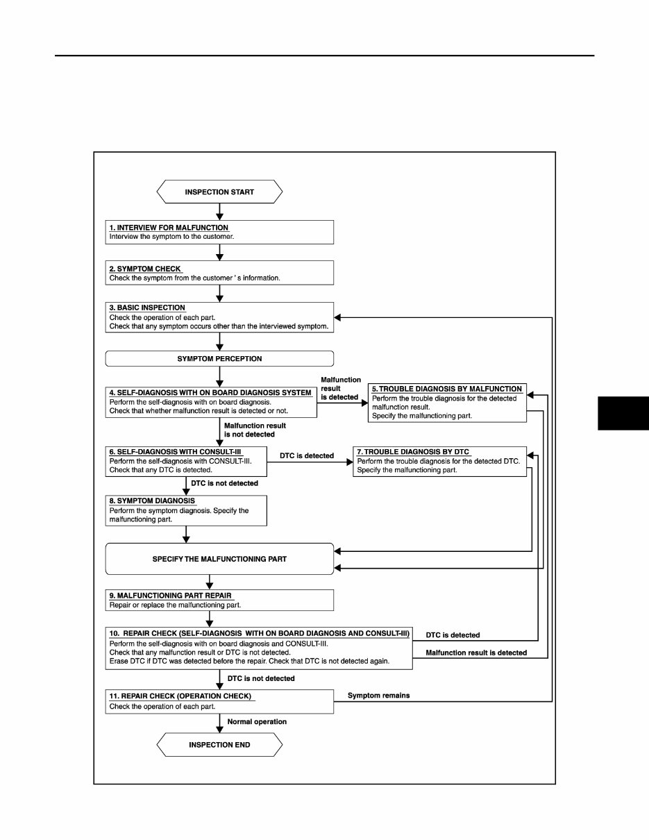
DIAGNOSIS AND REPAIR WORK FLOW HAC-5 < BASIC INSPECTION > [AUTOMATIC AIR CONDITIONING] C D E F G H J K L M A B HAC N O P BASIC INSPECTION DIAGNOSIS AND REPAIR WORK FLOW Work Flow INFOID:0000000005490026 OVERALL SEQUENCE DETAILED FLOW JPIIA1650GB Revision: 2009 October 2010 Z12
HAC-6 < BASIC INSPECTION > [AUTOMATIC AIR CONDITIONING] DIAGNOSIS AND REPAIR WORK FLOW 1.INTERVIEW FOR MALFUNCTION Interview the symptom to the customer. >> GO TO 2. 2.SYMPTOM CHECK Check the symptom from the customer's information. >> GO TO 3. 3.BASIC INSPECTION Check the operation of each part. Check that any symptom occurs other than the interviewed symptom. >> GO TO 4. 4.SELF-DIAGNOSIS WITH ON BOARD DIAGNOSIS SYSTEM Perform the self-diagnosis with on board diagnosis. Check that whether malfunction result is detected or not. Refer to HAC-26, " Diagnosis Description " . Is any malfunction result detected? YES >> GO TO 5. NO >> GO TO 6. 5.TROUBLE DIAGNOSIS BY MALFUNCTION Perform the trouble diagnosis for the detected malfunction result. Specify the malfunction part. >> GO TO 6. 6.SELF-DIAGNOSIS WITH CONSULT-III Perform the self-diagnosis with CONSULT-III. Check that any DTC is detected. Is any DTC detected? YES >> GO TO 7. NO >> GO TO 8. 7.TROUBLE DIAGNOSIS BY DTC Perform the trouble diagnosis for the detected DTC. Specify the malfunctioning part. >> GO TO 8. 8.SYMPTOM DIAGNOSIS Perform the symptom diagnosis. Specify the malfunctioning part. >> GO TO 9. 9.MALFUNCTION PART REPAIR Repair or replace the malfunctioning part. >> GO TO 10. 10.REPAIR CHECK (SELF-DIAGNOSIS WITH ON BOARD DIAGNOSIS AND CONSULT-III) Perform the self-diagnoses with on board diagnosis and CONSULT-III. Check that any DTC or malfunction result is not detected. Erase DTC if DTC is detected before the repair. Check that DTC is not detected again. Is any or malfunction result or DTC detected? YES-1 >> If malfunction result is detected, GO TO 5. YES-2 >> If DTC is detected, GO TO 7. NO >> GO TO 11. Revision: 2009 October 2010 Z12
DIAGNOSIS AND REPAIR WORK FLOW HAC-7 < BASIC INSPECTION > [AUTOMATIC AIR CONDITIONING] C D E F G H J K L M A B HAC N O P 11.REPAIR CHECK (OPERATION CHECK) Check the operation of each part. Does it operate normally? YES >> INSPECTION END NO >> GO TO 3. Revision: 2009 October 2010 Z12
HAC-8 < BASIC INSPECTION > [AUTOMATIC AIR CONDITIONING] INSPECTION INSPECTION Description & Inspection INFOID:0000000005490027 DESCRIPTION The purpose of the operational check is to check that the individual system operates normally. 1.CHECK MEMORY FUNCTION 1. Start the engine. 2. Set the temperature to 32°C (90°F) by operating the temperature control switch. 3. Press OFF switch. 4. Turn ignition switch OFF. 5. Turn ignition switch ON. 6. Press AUTO switch. 7. Check that the set temperature is maintained. Is the inspection result normal? YES >> GO TO 2. NO >> Memory function malfunction. Refer to HAC-140, " Inspection Procedure " . 2.CHECK BLOWER MOTOR 1. Start the engine. 2. Operate the fan control switch. Check that the fan speed changes. Check the operation for all fan speeds. 3. Leave blower on maximum speed. Is the inspection result normal? YES >> GO TO 3. NO >> Blower motor system malfunction. Refer to HAC-56, " Diagnosis Procedure " . 3.CHECK DISCHARGE AIR 1. Operate MODE switch and DEF switch to each position. 2. Check that the air outlets change according to each indicated air outlet by placing a hand in front of the outlets. Refer to VTL-2, " System Description " . Is the inspection result normal? YES >> GO TO 4. NO >> Mode door system malfunction. Refer to HAC-49, " Diagnosis Procedure " . 4.CHECK INTAKE AIR 1. Press REC switch to set the air outlet to recirculation. 2. The REC indicator turns ON. 3. Listen to intake sound and confirm air inlets change. 4. Press FRE switch again to set the air outlet to fresh air intake. 5. The FRE indicator turns ON. 6. Listen to intake sound and confirm air inlets change. Is the inspection result normal? YES >> GO TO 5. NO >> Intake door system malfunction. Refer to HAC-52, " Diagnosis Procedure " . 5.CHECK A/C SWITCH 1. Press the A/C switch. 2. Check that the indicator of the A/C switch turns ON. Check visually and by sound that the compressor operates. 3. Press the A/C switch again. 4. Check that the indicator of the A/C switch turns OFF. Check that the compressor stops. Is the inspection result normal? YES >> GO TO 6. NO >> Magnet clutch system malfunction. Refer to HAC-61, " Diagnosis Procedure " . Check condition : Engine running at normal operating temperature. Revision: 2009 October 2010 Z12
INSPECTION HAC-9 < BASIC INSPECTION > [AUTOMATIC AIR CONDITIONING] C D E F G H J K L M A B HAC N O P 6.CHECK DISCHARGE AIR TEMPERATURE Operate the temperature control switch. Check that the discharge air temperature changes. Is the inspection result normal? YES >> GO TO 7. NO >> Air mix door system malfunction. Refer to HAC-46, " Diagnosis Procedure " . 7.CHECK TEMPERATURE DECREASE 1. Operate the compressor. 2. Operate the temperature control switch to lower temperature setting at 18°C (60°F). 3. Check that the cool air blows from the outlets. Is the inspection result normal? YES >> GO TO 8. NO >> Insufficient cooling. Refer to HAC-135, " Diagnosis Procedure " . 8.CHECK TEMPERATURE INCREASE 1. Turn temperature control switch to raise temperature setting at 32°C (90°F) after warming up the engine. 2. Check that warm air blows from outlets. Is the inspection result normal? YES >> GO TO 9. NO >> Insufficient heating. Refer to HAC-137, " Diagnosis Procedure " . 9.CHECK AUTO MODE 1. Press AUTO switch to confirm that “AUTO” is indicated on the display. 2. Operate the temperature control switch to check that the fan speed or air outlet changes (the air flow tem- perature or fan speed varies depending on the ambient temperature, in-vehicle temperature, and set tem- perature). Is the inspection result normal? YES >> INSPECTION END NO >> Refer to HAC-134, " Diagnosis Chart By Symptom " and perform the appropriate diagnosis. Revision: 2009 October 2010 Z12
HAC-10 < BASIC INSPECTION > [AUTOMATIC AIR CONDITIONING] AUXILIARY MECHANISM AUXILIARY MECHANISM Temperature Setting Trimmer INFOID:0000000005490028 DESCRIPTION If the temperature felt by the customer is different than the air flow temperature controlled by the temperature setting, the A/C auto amp. control temperature can be adjusted to compensate for the temperature setting. OPERATING PROCEDURES 1. Begin self-diagnosis STEP 5 mode. Refer to HAC-26, " Diagnosis Description " . 2. Press fan control switch (up: +) to enter the set temperature setting trimmer mode from STEP 5, and then display shows “0°C (0°F)”. 3. The indication temperature will be changed by 1°C (1°F) in range of −3°C (−6°F) to +3°C (+6°F) by press- ing the temperature control switch each time. USA models Canada models NOTE: • When −3°C (−6°F) is corrected on the temperature setting set as 25°C (75°F), the temperature controlled by A/C auto amp. is 25°C (75°F) − 3°C (6°F) = 22.0°C (69°F) and the temperature becomes lower than the tem- perature setting. • When the battery cable is disconnected from the negative terminal or when the battery voltage becomes 10 V or less, the setting of the difference between the set temperature and control temperature may be can- celled. Temperature control switch operation Display Correction (°F) 6 time pressing 6 +6 5 time pressing 5 +5 4 time pressing 4 +4 3 time pressing 3 +3 2 time pressing 2 +2 1 time pressing 1 +1 Initial status 0 0 1 time pressing AUTO 1 −1 2 time pressing AUTO 2 −2 3 time pressing AUTO 3 −3 4 time pressing AUTO 4 −4 5 time pressing AUTO 5 −5 6 time pressing AUTO 6 −6 Temperature control switch operation Display Correction (°C) 3 time pressing 3 +3 2 time pressing 2 +2 1 time pressing 1 +1 Initial status 0 0 1 time pressing AUTO 1 −1 2 time pressing AUTO 2 −2 3 time pressing AUTO 3 −3 Revision: 2009 October 2010 Z12
If you are in need of a repair manual for your 2010 Nissan Cube, look no further. Our accessible repair manual is the perfect resource for both professional mechanics and DIY enthusiasts. In the past, traditional paper repair manuals were the norm, but our digital format offers a more cost-effective and convenient alternative.
Whether you are tackling brake repairs, suspension component replacements, engine troubleshooting, or standard maintenance tasks, this repair manual has you covered. It provides comprehensive service information for the brakes, engine, suspension, steering, drivetrain, electrical systems, heating, air conditioning, and more.
By utilizing this 2010 Nissan Cube repair manual , you can save a significant amount of money on vehicle maintenance. Mechanics often charge high fees for their services, making a DIY approach a cost-effective solution. The is compatible with Windows, Mac computers, smartphones, and tablets, ensuring ease of use for all users.