

2017 Nissan Armada (Y62) Service & Repair Manual
What's Included?
Fast Download Speeds
Offline Viewing
Access Contents & Bookmarks
Full Search Facility
Print one or all pages of your manual

ACC-1
ENGINE
C
D
E
F
G
H
I
J
K
L
M
SECTION ACC
A
ACC
N
O
P
CONTENTS
ACCELERATOR CONTROL SYSTEM
PRECAUTION .............................................. 2
PRECAUTIONS .................................................. 2
Precautions for Removing Battery Terminal ............ 2
Precaution for Supplemental Restraint System
(SRS) "AIR BAG" and "SEAT BELT PRE-TEN-
SIONER" .................................................................. 2
REMOVAL AND INSTALLATION ............... 4
ACCELERATOR CONTROL SYSTEM .............. 4
MODELS WITHOUT DISTANCE CONTROL AS-
SIST SYSTEM ............................................................ 4
MODELS WITHOUT DISTANCE CONTROL AS-
SIST SYSTEM : Exploded View .............................. 4
MODELS WITHOUT DISTANCE CONTROL AS-
SIST SYSTEM : Removal and Installation .............. 4
MODELS WITHOUT DISTANCE CONTROL AS-
SIST SYSTEM : Inspection ..................................... 4
MODELS WITH DISTANCE CONTROL ASSIST
SYSTEM ..................................................................... 5
MODELS WITH DISTANCE CONTROL ASSIST
SYSTEM : Exploded View ....................................... 5
MODELS WITH DISTANCE CONTROL ASSIST
SYSTEM : Removal and Installation ....................... 5
MODELS WITH DISTANCE CONTROL ASSIST
SYSTEM : Inspection .............................................. 5
Revision: June 2016 2017 Armada
ACC-2
< PRECAUTION >
PRECAUTIONS
PRECAUTION
PRECAUTIONS
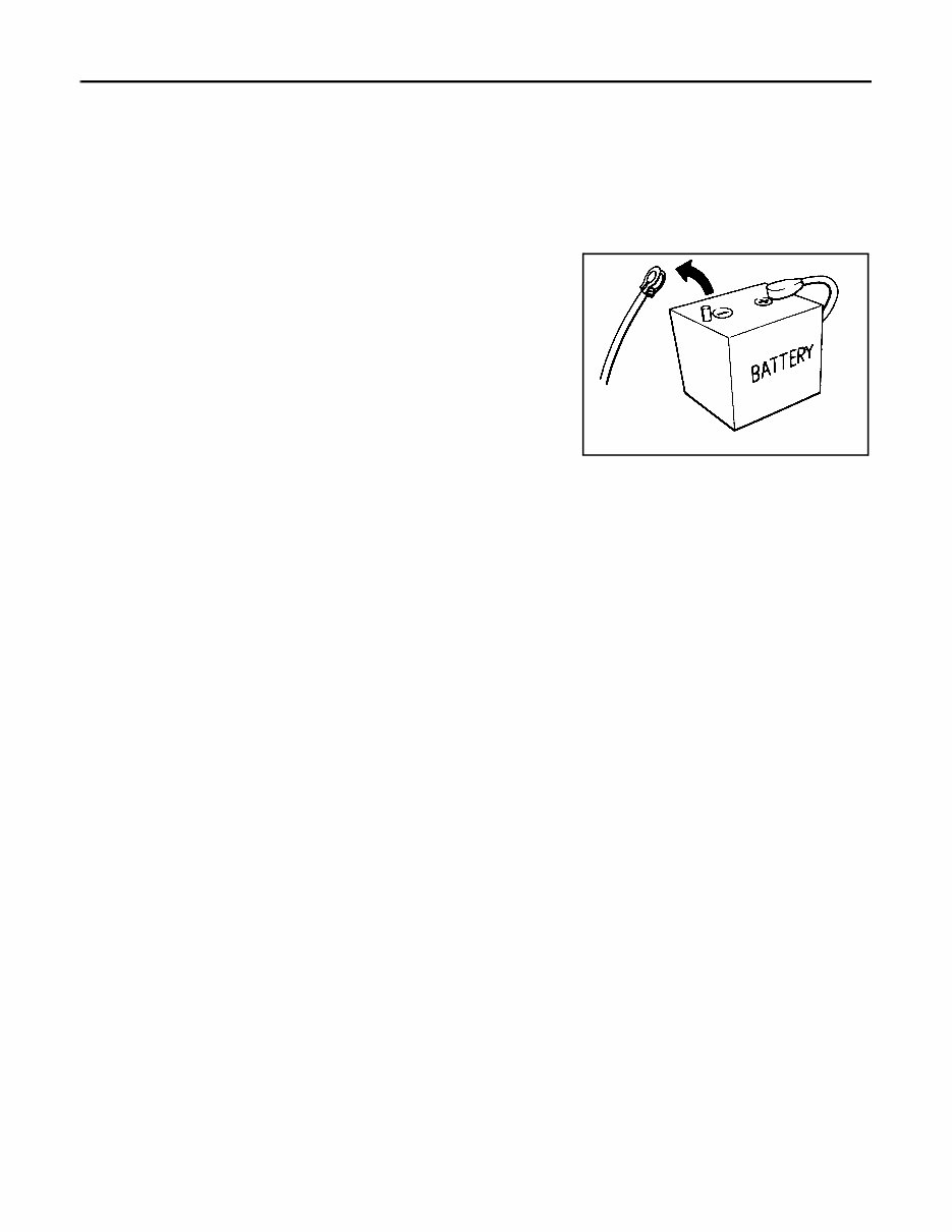
Precautions for Removing Battery Terminal INFOID:0000000013728536
When disconnecting the battery terminal, pay attention to the following.
• Always use a 12V battery as power source.
• Never disconnect battery terminal while engine is running.
• When removing the 12V battery terminal, turn OFF the ignition
switch and wait at least 30 seconds.
• For vehicles with the engine listed below, remove the battery termi-
nal after a lapse of the specified time:
NOTE:
ECU may be active for several tens of seconds after the ignition switch is turned OFF. If the battery terminal
is removed before ECU stops, then a DTC detection error or ECU data corruption may occur.
• After high-load driving, if the vehicle is equipped with the V9X engine, turn the ignition switch OFF and wait
for at least 15 minutes to remove the battery terminal.
NOTE:
• Turbocharger cooling pump may operate in a few minutes after the ignition switch is turned OFF.
• Example of high-load driving
- Driving for 30 minutes or more at 140 km/h (86 MPH) or more.
- Driving for 30 minutes or more on a steep slope.
• For vehicles with the 2-batteries, be sure to connect the main battery and the sub battery before turning ON
the ignition switch.
NOTE:
If the ignition switch is turned ON with any one of the terminals of main battery and sub battery discon-
nected, then DTC may be detected.
• After installing the 12V battery, always check "Self Diagnosis Result" of all ECUs and erase DTC.
NOTE:
The removal of 12V battery may cause a DTC detection error.
Precaution for Supplemental Restraint System (SRS) "AIR BAG" and "SEAT BELT
PRE-TENSIONER" INFOID:0000000013728537
The Supplemental Restraint System such as “AIR BAG” and “SEAT BELT PRE-TENSIONER”, used along
with a front seat belt, helps to reduce the risk or severity of injury to the driver and front passenger for certain
types of collision. Information necessary to service the system safely is included in the “SRS AIR BAG” and
“SEAT BELT” of this Service Manual.
WARNING:
Always observe the following items for preventing accidental activation.
• To avoid rendering the SRS inoperative, which could increase the risk of personal injury or death in
the event of a collision that would result in air bag inflation, it is recommended that all maintenance
and repair be performed by an authorized NISSAN/INFINITI dealer.
• Improper repair, including incorrect removal and installation of the SRS, can lead to personal injury
caused by unintentional activation of the system. For removal of Spiral Cable and Air Bag Module,
see “SRS AIR BAG”.
• Never use electrical test equipment on any circuit related to the SRS unless instructed to in this Ser-
vice Manual. SRS wiring harnesses can be identified by yellow and/or orange harnesses or harness
connectors.
PRECAUTIONS WHEN USING POWER TOOLS (AIR OR ELECTRIC) AND HAMMERS
BR08DE : 4 minutes YD25DDTi : 2 minutes
D4D engine : 20 minutes YS23DDT : 4 minutes
HRA2DDT : 12 minutes YS23DDTT : 4 minutes
K9K engine : 4 minutes ZD30DDTi : 60 seconds
M9R engine : 4 minutes ZD30DDTT : 60 seconds
R9M engine : 4 minutes
V9X engine : 4 minutes
SEF289H
Revision: June 2016 2017 Armada

PRECAUTIONS
ACC-3
< PRECAUTION >
C
D
E
F
G
H
I
J
K
L
M
A
ACC
N
P
O
WARNING:
Always observe the following items for preventing accidental activation.
• When working near the Air Bag Diagnosis Sensor Unit or other Air Bag System sensors with the
ignition ON or engine running, never use air or electric power tools or strike near the sensor(s) with
a hammer. Heavy vibration could activate the sensor(s) and deploy the air bag(s), possibly causing
serious injury.
• When using air or electric power tools or hammers, always switch the ignition OFF, disconnect the
battery or batteries, and wait at least 3 minutes before performing any service.
Revision: June 2016 2017 Armada
ACC-4
< REMOVAL AND INSTALLATION >
ACCELERATOR CONTROL SYSTEM
REMOVAL AND INSTALLATION
ACCELERATOR CONTROL SYSTEM
MODELS WITHOUT DISTANCE CONTROL ASSIST SYSTEM
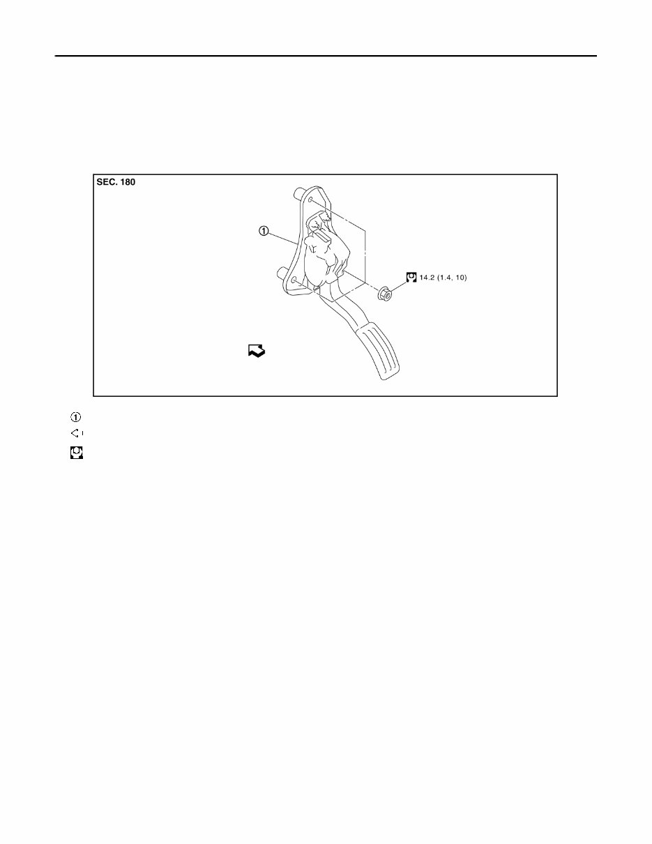
MODELS WITHOUT DISTANCE CONTROL ASSIST SYSTEM : Exploded View
INFOID:0000000013728538
MODELS WITHOUT DISTANCE CONTROL ASSIST SYSTEM : Removal and Instal-
lation INFOID:0000000013728539
REMOVAL
1. Remove the inside mounting nuts.
2. Remove accelerator pedal assembly.
3. Disconnect accelerator pedal position sensor harness connector.
CAUTION:
• Never disassemble accelerator pedal assembly.
• Never remove accelerator pedal position sensor from accelerator pedal assembly.
• Avoid impact from dropping etc. during handling.
• Be careful to keep accelerator lever away from water.
INSTALLATION
Installation is the reverse order of removal.
MODELS WITHOUT DISTANCE CONTROL ASSIST SYSTEM : Inspection
INFOID:0000000013728540
INSPECTION AFTER INSTALLATION
• Check accelerator pedal moves smoothly within the whole operation range when it is fully depressed and
released.
• Check accelerator pedal securely returns to the fully released position.
• For the electrical inspection of accelerator pedal position sensor, refer to the following:
Accelerator pedal assembly
: Vehicle front
: N·m (kg-m, ft-lb)
JSBIA3158GB
Revision: June 2016 2017 Armada
ACCELERATOR CONTROL SYSTEM
ACC-5
< REMOVAL AND INSTALLATION >
C
D
E
F
G
H
I
J
K
L
M
A
ACC
N
P
O
CAUTION:
When harness connector of accelerator pedal position sensor is disconnected, perform “Accelerator
Pedal Released Position Learning”. Refer to EC-174, "Description" .
MODELS WITH DISTANCE CONTROL ASSIST SYSTEM
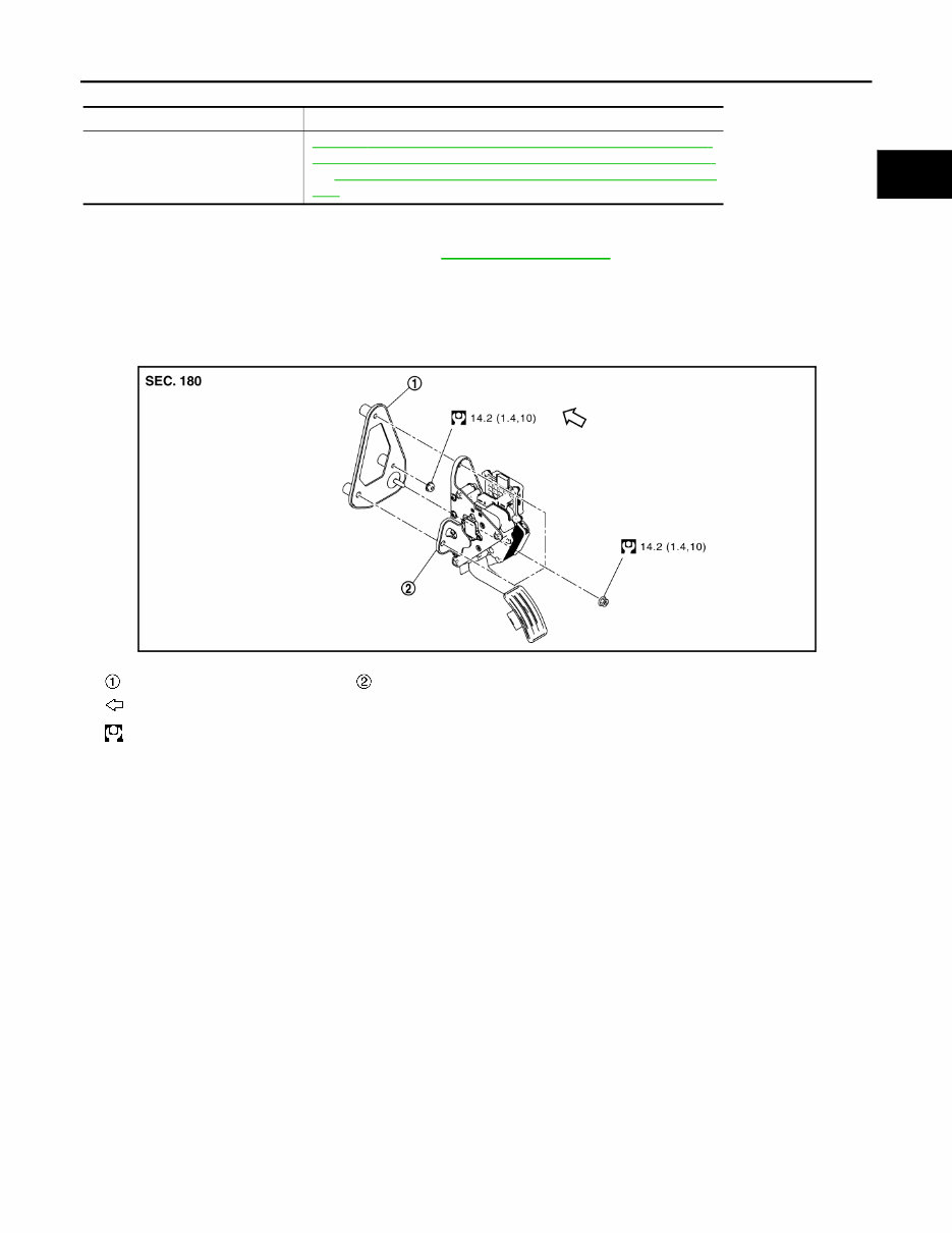
MODELS WITH DISTANCE CONTROL ASSIST SYSTEM : Exploded View
INFOID:0000000013728541
MODELS WITH DISTANCE CONTROL ASSIST SYSTEM : Removal and Installation
INFOID:0000000013728542
REMOVAL
1. Remove the inside mounting nuts.
2. Remove accelerator pedal assembly.
3. Disconnect accelerator pedal actuator harness connector and accelerator pedal position sensor harness
connector.
CAUTION:
• Never disassemble accelerator pedal assembly.
• Never remove accelerator pedal position sensor from accelerator pedal assembly.
• Avoid impact from dropping etc. during handling.
• Be careful to keep accelerator pedal assembly away from water.
4. Remove accelerator pedal bracket, if necessary.
INSTALLATION
Installation is the reverse order of removal.
MODELS WITH DISTANCE CONTROL ASSIST SYSTEM : Inspection INFOID:0000000013728543
INSPECTION AFTER INSTALLATION
Engine Reference page
VK56VD
EC-590, " Component Inspection (Accelerator Pedal Position Sensor) " ,
EC-593, " Component Inspection (Accelerator Pedal Position Sensor) "
andEC-599, " Component Inspection (Accelerator Pedal Position Sen-
sor) " .
Accelerator pedal bracket Accelerator pedal assembly
Vehicle front
: N·m (kg-m, ft-lb)
JPBIA6417GB
Revision: June 2016 2017 Armada

ACC-6
< REMOVAL AND INSTALLATION >
ACCELERATOR CONTROL SYSTEM
• Check accelerator pedal moves smoothly within the whole operation range when it is fully depressed and
released.
• Check accelerator pedal securely returns to the fully released position.
• For the electrical inspection of accelerator pedal position sensor, refer to the following:
CAUTION:
When harness connector of accelerator pedal position sensor is disconnected, perform “Accelerator
Pedal Released Position Learning”. Refer to EC-174, "Description" .
Engine Reference page
VK56VD
EC-590, " Component Inspection (Accelerator Pedal Position Sensor) " ,
EC-593, " Component Inspection (Accelerator Pedal Position Sensor) "
and EC-599, " Component Inspection (Accelerator Pedal Position Sen-
sor) " .
Revision: June 2016 2017 Armada
You're Reading a Preview
What's Included?
Fast Download Speeds
Offline Viewing
Access Contents & Bookmarks
Full Search Facility
Print one or all pages of your manual
$35.99
Viewed 40 Times Today


Secure transaction
What's Included?
Fast Download Speeds
Offline Viewing
Access Contents & Bookmarks
Full Search Facility
Print one or all pages of your manual
$35.99
This workshop manual contains maintenance and repair procedures for the 2017 Nissan Armada Y62. It also includes a wiring diagram.
Size: 213 MB
Format: .PDF


