CHG CHG-1 ELECTRICAL & POWER CONTROL C D E F G H I J K L B SECTION CHG A O P N CONTENTS CHARGING SYSTEM PRECAUTION .............................................. 2 PRECAUTIONS .................................................. 2 Precaution for Supplemental Restraint System (SRS) "AIR BAG" and "SEAT BELT PRE-TEN- SIONER" .................................................................. 2 Precaution Necessary for Steering Wheel Rota- tion After Battery Disconnect .................................... 2 Precaution for Power Generation Variable Voltage Control System ......................................................... 3 PREPARATION ........................................... 4 PREPARATION .................................................. 4 Special Service Tool ................................................ 4 Commercial Service Tool ......................................... 4 BASIC INSPECTION ................................... 5 DIAGNOSIS AND REPAIR WORKFLOW ......... 5 Work Flow (With EXP-800 NI or GR8-1200 NI) ....... 5 Work Flow (Without EXP-800 NI or GR8-1200 NI) ...... 8 SYSTEM DESCRIPTION ............................ 11 CHARGING SYSTEM ........................................11 System Diagram ..................................................... 11 System Description ................................................ 11 Component Description ......................................... 11 POWER GENERATION VOLTAGE VARI- ABLE CONTROL SYSTEM ...............................12 System Diagram ..................................................... 12 System Description ................................................ 12 Component Description .......................................... 12 DTC/CIRCUIT DIAGNOSIS ........................ 13 CHARGING SYSTEM PRELIMINARY IN- SPECTION .........................................................13 Inspection Procedure ............................................. 13 POWER GENERATION VOLTAGE VARI- ABLE CONTROL SYSTEM OPERATION IN- SPECTION ........................................................ 14 Inspection Procedure ..............................................14 B TERMINAL CIRCUIT ..................................... 16 Description ..............................................................16 Diagnosis Procedure ..............................................16 L TERMINAL CIRCUIT (OPEN) ........................ 17 Description ..............................................................17 Diagnosis Procedure ..............................................17 L TERMINAL CIRCUIT (SHORT) ..................... 19 Description ..............................................................19 Diagnosis Procedure ..............................................19 S TERMINAL CIRCUIT ..................................... 20 Description ..............................................................20 Diagnosis Procedure ..............................................20 WIRING DIAGRAM ..................................... 21 CHARGING SYSTEM ....................................... 21 Wiring Diagram .......................................................21 SYMPTOM DIAGNOSIS ............................. 27 CHARGING SYSTEM ....................................... 27 Symptom Table ......................................................27 REMOVAL AND INSTALLATION .............. 28 GENERATOR .................................................... 28 Removal and Installation ........................................28 SERVICE DATA AND SPECIFICATIONS (SDS) ........................................................... 29 GENERATOR .................................................... 29 Generator ...............................................................29 Revision: July 2012 2012 Armada
CHG-2 < PRECAUTION > PRECAUTIONS PRECAUTION PRECAUTIONS Precaution for Supplemental Restraint System (SRS) "AIR BAG" and "SEAT BELT PRE-TENSIONER" INFOID:0000000007316509 The Supplemental Restraint System such as “AIR BAG” and “SEAT BELT PRE-TENSIONER”, used along with a front seat belt, helps to reduce the risk or severity of injury to the driver and front passenger for certain types of collision. This system includes seat belt switch inputs and dual stage front air bag modules. The SRS system uses the seat belt switches to determine the front air bag deployment, and may only deploy one front air bag, depending on the severity of a collision and whether the front occupants are belted or unbelted. Information necessary to service the system safely is included in the SR and SB section of this Service Man- ual. WARNING: • To avoid rendering the SRS inoperative, which could increase the risk of personal injury or death in the event of a collision which would result in air bag inflation, all maintenance must be performed by an authorized NISSAN/INFINITI dealer. • Improper maintenance, including incorrect removal and installation of the SRS, can lead to personal injury caused by unintentional activation of the system. For removal of Spiral Cable and Air Bag Module, see the SR section. • Do not use electrical test equipment on any circuit related to the SRS unless instructed to in this Service Manual. SRS wiring harnesses can be identified by yellow and/or orange harnesses or har- ness connectors. PRECAUTIONS WHEN USING POWER TOOLS (AIR OR ELECTRIC) AND HAMMERS WARNING: • When working near the Airbag Diagnosis Sensor Unit or other Airbag System sensors with the Igni- tion ON or engine running, DO NOT use air or electric power tools or strike near the sensor(s) with a hammer. Heavy vibration could activate the sensor(s) and deploy the air bag(s), possibly causing serious injury. • When using air or electric power tools or hammers, always switch the Ignition OFF, disconnect the battery, and wait at least 3 minutes before performing any service. Precaution Necessary for Steering Wheel Rotation After Battery Disconnect INFOID:0000000007316510 NOTE: • This Procedure is applied only to models with Intelligent Key system and NATS (NISSAN ANTI-THEFT SYSTEM). • Remove and install all control units after disconnecting both battery cables with the ignition knob in the ″LOCK″ position. • Always use CONSULT to perform self-diagnosis as a part of each function inspection after finishing work. If DTC is detected, perform trouble diagnosis according to self-diagnostic results. For models equipped with the Intelligent Key system and NATS, an electrically controlled steering lock mech- anism is adopted on the key cylinder. For this reason, if the battery is disconnected or if the battery is discharged, the steering wheel will lock and steering wheel rotation will become impossible. If steering wheel rotation is required when battery power is interrupted, follow the procedure below before starting the repair operation. OPERATION PROCEDURE 1. Connect both battery cables. NOTE: Supply power using jumper cables if battery is discharged. 2. Use the Intelligent Key or mechanical key to turn the ignition switch to the ″ACC″ position. At this time, the steering lock will be released. 3. Disconnect both battery cables. The steering lock will remain released and the steering wheel can be rotated. 4. Perform the necessary repair operation. Revision: July 2012 2012 Armada
CHG PRECAUTIONS CHG-3 < PRECAUTION > C D E F G H I J K L B A O P N 5. When the repair work is completed, return the ignition switch to the ″LOCK″ position before connecting the battery cables. (At this time, the steering lock mechanism will engage.) 6. Perform a self-diagnosis check of all control units using CONSULT. Precaution for Power Generation Variable Voltage Control System INFOID:0000000007316511 CAUTION: For this model, the battery current sensor that is installed to the negative battery cable measures the charging/discharging current of the battery and performs various engine controls. If an electrical com- ponent is connected directly to the negative battery terminal, the current flowing through that compo- nent will not be measured by the battery current sensor. This condition may cause a malfunction of the engine control system and battery discharge may occur. Do not connect an electrical component or ground wire directly to the battery terminal. Revision: July 2012 2012 Armada
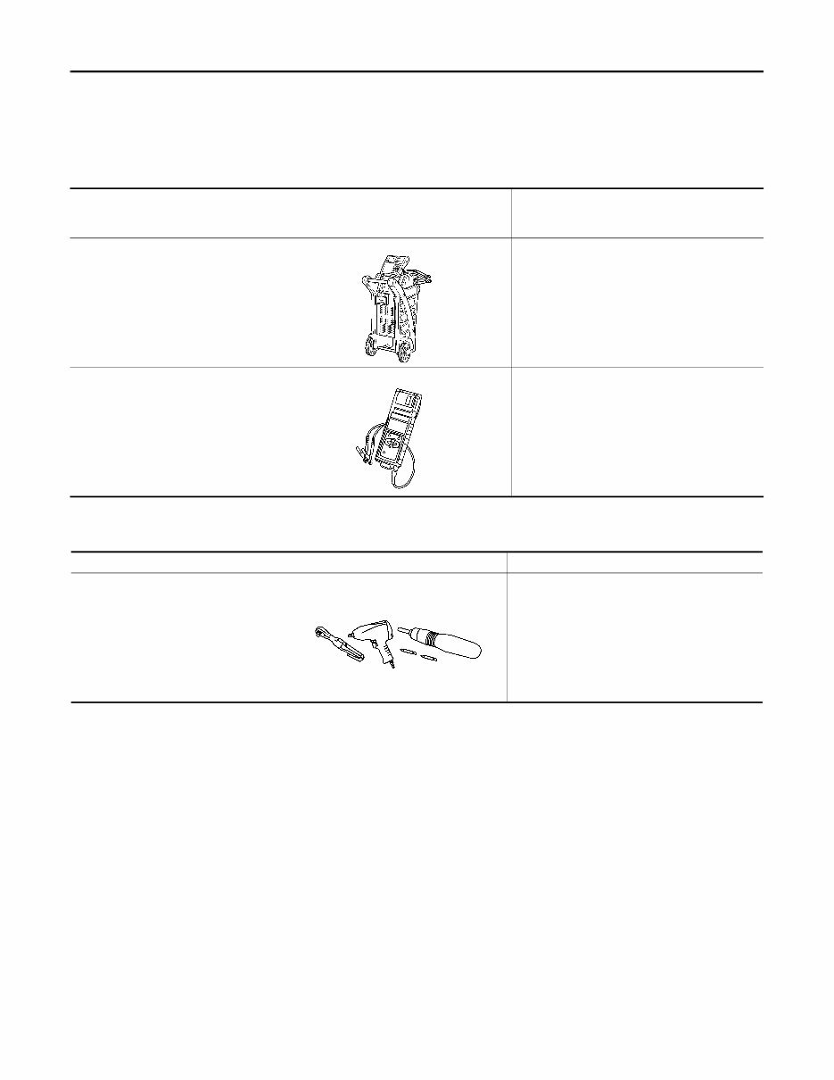
CHG-4 < PREPARATION > PREPARATION PREPARATION PREPARATION Special Service Tool INFOID:0000000007316512 The actual shapes of Kent-Moore tools may differ from those of special service tools illustrated here. Commercial Service Tool INFOID:0000000007316513 Tool number (Kent-Moore No.) Tool name Description — (—) Model GR8-1200 NI Multitasking battery and electrical di- agnostic station Tests batteries, starting and charging sys- tems and charges batteries. For operating instructions, refer to diagnostic station instruction manual. — (—) Model EXP-800 NI Battery and electrical diagnostic ana- lyzer Tests batteries and charging systems. For operating instructions, refer to diagnostic analyzer instruction manual. AWIIA1239ZZ JSMIA0806ZZ Tool name Description Power tool Loosening nuts, screws and bolts PIIB1407E Revision: July 2012 2012 Armada
CHG DIAGNOSIS AND REPAIR WORKFLOW CHG-5 < BASIC INSPECTION > C D E F G H I J K L B A O P N BASIC INSPECTION DIAGNOSIS AND REPAIR WORKFLOW Work Flow (With EXP-800 NI or GR8-1200 NI) INFOID:0000000007316514 CHARGING SYSTEM DIAGNOSIS WITH EXP-800 NI OR GR8-1200 NI To test the charging system, use the following special service tools: • EXP-800 NI Battery and electrical diagnostic analyzer • GR8-1200 NI Multitasking battery and electrical diagnostic station NOTE: Refer to the applicable Instruction Manual for proper charging system diagnosis procedures. Revision: July 2012 2012 Armada
The 2012 Nissan Armada Service & Repair Manual is the ultimate guide for those looking to maintain and repair their vehicle on their own. This comprehensive manual provides all the necessary troubleshooting and replacement procedures recommended by the manufacturer, complete with step-by-step instructions, exploded-view illustrations, and clear images.
Whether you are a seasoned mechanic or a novice car owner, this manual is a valuable tool to have. Regular maintenance is crucial for the durability of your vehicle, and with the help of this manual, you can easily keep up with it. And when it's time for parts to be replaced, the manual will guide you through the process to ensure your vehicle remains reliable and in top condition.
Gone are the days of flipping through hundreds of pages to find the information you need. With this electronic manual, you can easily search for specific information, bookmark pages, and even take screenshots for future reference. No more worrying about greasy, torn, or lost pages - the manual can be carried around on any electronic device, whether it's a PC, Mac, smartphone, or tablet.
But if you prefer a physical copy, you can easily print out the manual as well. It's compatible with pretty much any electronic device, making it easily accessible for anyone. All you need is Adobe Reader, which is free to download.
Invest in the 2012 Nissan Armada Service & Repair Manual and take control of maintaining and repairing your vehicle. With this manual by your side, you can save on repairs, increase your vehicle's reliability, and keep the repair shop at bay. Don't wait any longer - get your hands on this essential manual today!