HAC-1 VENTILATION, HEATER & AIR CONDITIONER C D E F G H J K L M SECTION HAC A B HAC N O P CONTENTS HEATER & AIR CONDITIONING CONTROL SYSTEM AUTOMATIC AIR CONDITIONER BASIC INSPECTION ................................... 3 DIAGNOSIS AND REPAIR WORKFLOW ......... 3 How to Perform Trouble Diagnosis For Quick And Accurate Repair ....................................................... 3 INSPECTION AND ADJUSTMENT .................... 4 Operational Check (Front) ........................................ 4 Operational Check (Rear) ........................................ 5 SYSTEM DESCRIPTION ............................. 7 FUNCTION INFORMATION ............................... 7 Component Part Location ........................................ 7 Symptom Table ........................................................ 9 REFRIGERATION SYSTEM .............................11 Refrigerant Cycle ................................................... 11 Refrigerant System Protection ............................... 11 AUTOMATIC AIR CONDITIONER SYSTEM ....13 Control System Diagram ........................................ 13 Control System Description .................................... 13 Discharge Air Flow (Front) ..................................... 16 Discharge Air Flow (Rear) ...................................... 16 Switches And Their Control Function (Front) ......... 18 Switches And Their Control Function (Rear) .......... 19 DIAGNOSIS SYSTEM (HVAC) .........................20 CONSULT-III Function (HVAC) .............................. 20 DIAGNOSIS SYSTEM (BCM) ...........................21 CONSULT-III Function (BCM - COMMON ITEM) .... 21 CONSULT-III Function (BCM - AIR CONDITION- ER) ......................................................................... 22 SELF-DIAGNOSIS FUNCTION .........................23 A/C Auto Amp. Self-Diagnosis ............................... 23 A/C and AV Switch Assembly Self-Diagnosis ........ 23 A/C System Self-Diagnosis Code Chart ................. 24 DTC/CIRCUIT DIAGNOSIS ........................ 25 MODE DOOR MOTOR ...................................... 25 System Description .................................................25 Mode Door Motor (Front) Component Function Check .....................................................................26 Mode Door Motor (Front) Diagnosis Procedure .....26 AIR MIX DOOR MOTOR ................................... 30 System Description .................................................30 Air Mix Door Motor (Driver) Component Function Check .....................................................................31 Air Mix Door Motor (Driver) Diagnosis Procedure ....31 Air Mix Door Motor (Passenger) Component Function Check .......................................................34 Air Mix Door Motor (Passenger) Diagnosis Proce- dure ........................................................................35 INTAKE DOOR MOTOR ................................... 39 System Description .................................................39 Intake Door Motor Component Function Check .....40 Intake Door Motor Diagnosis Procedure ................40 DEFROSTER DOOR MOTOR CIRCUIT ........... 42 System Description .................................................42 Defroster Door Motor Component Function Check ....43 Defroster Door Motor Diagnosis Procedure ...........43 BLOWER MOTOR CONTROL SYSTEM .......... 47 System Description .................................................47 Front Blower Motor Component Function Check .... 48 Front Blower Motor Diagnosis Procedure ...............48 Front Blower Motor Component Inspection ............52 Rear Blower Motor Description ...............................52 Rear Blower Motor Component Function Check ....53 Rear Air Control (Front) Diagnosis Procedure #1....54 Rear Air Control (Rear) Diagnosis Procedure #2 ....55 Rear Blower Motor Component Inspection .............56 REAR AIR CONTROL SYSTEM ....................... 58 Rear Air Control System Description ......................58 Revision: July 2010 2011 Armada
HAC-2 Rear Air Control Component Function Check ....... 58 Air Mix Door Motor (Rear) Diagnosis Procedure ... 59 Mode Door Motor (Rear) Diagnosis Procedure ..... 63 MAGNET CLUTCH ........................................... 67 System Description ................................................ 67 Magnet Clutch Component Function Check .......... 67 Magnet Clutch Diagnosis Procedure ..................... 67 WATER VALVE CIRCUIT ................................. 72 Description ............................................................. 72 Water Valve Diagnosis Procedure ......................... 72 AMBIENT SENSOR .......................................... 74 Component Description ......................................... 74 Ambient Sensor Diagnosis Procedure ................... 74 Ambient Sensor Component Inspection ................ 75 IN-VEHICLE SENSOR ...................................... 77 Component Description ......................................... 77 In-Vehicle Sensor Diagnosis Procedure ................ 77 In-Vehicle Sensor Component Inspection ............. 79 OPTICAL SENSOR .......................................... 80 Component Description ......................................... 80 Optical Sensor Diagnosis Procedure ..................... 80 INTAKE SENSOR ............................................. 82 System Description ................................................ 82 Intake Sensor Diagnosis Procedure ...................... 82 Intake Sensor Component Inspection ................... 83 POWER SUPPLY AND GROUND CIRCUIT FOR CONTROLLER ......................................... 85 Component Description ......................................... 85 A/C Auto Amp. Component Function Check ......... 85 A/C Auto Amp Power and Ground Diagnosis Pro- cedure .................................................................... 86 ECU DIAGNOSIS INFORMATION ............. 88 AIR CONDITIONER CONTROL ....................... 88 A/C Auto Amp. Terminals Reference Values ......... 88 WIRING DIAGRAM .................................... 90 AIR CONDITIONER CONTROL ....................... 90 Wiring Diagram ...................................................... 90 SYMPTOM DIAGNOSIS ........................... 106 AIR CONDITIONER CONTROL ...................... 106 Symptom Matrix Chart ........................................ 106 INSUFFICIENT COOLING ............................... 107 Component Function Check ................................ 107 Diagnostic Work Flow .......................................... 108 Performance Chart ............................................... 111 Trouble Diagnoses for Abnormal Pressure .......... 112 INSUFFICIENT HEATING ............................... 115 Component Function Check ................................ 115 NOISE .............................................................. 117 Component Function Check ................................ 117 MEMORY FUNCTION DOES NOT OPERATE .. 119 Memory Function Check ...................................... 119 PRECAUTION ........................................... 120 PRECAUTIONS ............................................... 120 Precaution for Supplemental Restraint System (SRS) "AIR BAG" and "SEAT BELT PRE-TEN- SIONER" .............................................................. 120 Precaution Necessary for Steering Wheel Rota- tion After Battery Disconnect ............................... 120 Working with HFC-134a (R-134a) ........................ 121 Precaution for Service Equipment ....................... 121 Revision: July 2010 2011 Armada
DIAGNOSIS AND REPAIR WORKFLOW HAC-3 < BASIC INSPECTION > [AUTOMATIC AIR CONDITIONER] C D E F G H J K L M A B HAC N O P BASIC INSPECTION DIAGNOSIS AND REPAIR WORKFLOW How to Perform Trouble Diagnosis For Quick And Accurate Repair INFOID:0000000006145402 WORK FLOW 1.LISTEN TO CUSTOMER COMPLAINT Listen to customer complaint. Get detailed information about the conditions and environment when the symp- tom occurs. >> GO TO 2 2.CHECK FOR SERVICE BULLETINS Check for any service bulletins. >> GO TO 3. 3.VERIFY THE SYMPTOM WITH OPERATIONAL CHECK Verify the symptom with operational check. Refer to HAC-4, " Operational Check (Front) " . Can a symptom be duplicated? YES >> GO TO 4 NO >> GO TO 5 4.GO TO APPROPRIATE TROUBLE DIAGNOSIS Go to appropriate trouble diagnosis. Refer to HAC-106, " Symptom Matrix Chart " . Can a symptom be duplicated? >> GO TO 5. 5.PERFORM THE A/C AUTO AMP SELF-DIAGNOSIS Perform A/C auto amp. self-diagnosis. Refer to HAC-23, " A/C Auto Amp. Self-Diagnosis " . >> If any diagnostic trouble codes set. Refer to HAC-24, " A/C System Self-Diagnosis Code Chart " . >> Confirm the repair by performing operational check. Refer to HAC-4, " Operational Check (Front) " . Revision: July 2010 2011 Armada
HAC-4 < BASIC INSPECTION > [AUTOMATIC AIR CONDITIONER] INSPECTION AND ADJUSTMENT INSPECTION AND ADJUSTMENT Operational Check (Front) INFOID:0000000006145403 The purpose of the operational check is to confirm that the system operates properly. CHECKING MEMORY FUNCTION 1. Set the temperature to 32° (90°F). 2. Press the OFF switch. 3. Turn ignition switch OFF. 4. Turn ignition switch ON. 5. Press the AUTO switch. 6. Confirm that the set temperature remains at previous temperature. 7. Press the OFF switch. If NG, go to trouble diagnosis procedure for HAC-119, " Memory Function Check " . If OK, continue with next check. CHECKING BLOWER 1. Press the blower speed control switch (+) once, blower should operate on low speed. The fan display should have one bar lit (on display). 2. Press the blower speed control switch (+) again, and continue checking blower speed and fan display until all speeds are checked. 3. Leave blower on maximum speed. If NG, go to trouble diagnosis procedure for HAC-48, " Front Blower Motor Diagnosis Procedure " . If OK, continue with next check. CHECKING DISCHARGE AIR 1. Press MODE switch four times and the DEF switch. 2. Each position indicator should change shape (on display). 3. Confirm that discharge air comes out according to the air distribution table. Refer to HAC-16, " Discharge Air Flow (Front) " . Mode door position is checked in the next step. If NG, go to trouble diagnosis procedure for HAC-26, " Mode Door Motor (Front) Diagnosis Procedure " . If OK, continue the check. NOTE: Confirm that the compressor clutch is engaged (sound or visual inspection) and intake door position is at fresh when the DEF or D/F is selected. CHECKING RECIRCULATION ( , ONLY) 1. Press recirculation ( ) switch one time. Recirculation indicator should illuminate. 2. Press recirculation ( ) switch one more time. Recirculation indicator should go off. 3. Listen for intake door position change (blower sound should change slightly). If NG, go to trouble diagnosis procedure for HAC-40, " Intake Door Motor Diagnosis Procedure " . If OK, continue the check. NOTE: Confirm that the compressor clutch is engaged (sound or visual inspection) and intake door position is at fresh when the DEF or D/F is selected. REC ( ) is not allowed in DEF ( ) D/F ( ) or FOOT ( ). CHECKING TEMPERATURE DECREASE 1. Rotate temperature control dial (drive or passenger) counterclockwise until 18°C (60°F) is displayed. 2. Check for cold air at appropriate discharge air outlets. Conditions : Engine running and at normal operating temperature Revision: July 2010 2011 Armada
INSPECTION AND ADJUSTMENT HAC-5 < BASIC INSPECTION > [AUTOMATIC AIR CONDITIONER] C D E F G H J K L M A B HAC N O P If NG, listen for sound of air mix door motor operation. If OK, go to trouble diagnosis procedure for HAC-107, " Component Function Check " . If air mix door motor appears to be malfunctioning, go to HAC-31, " Air Mix Door Motor (Driver) Component Function Check " . If OK, continue the check. CHECKING TEMPERATURE INCREASE 1. Rotate temperature control dial clockwise (drive or passenger) until 32°C (90°F) is displayed. 2. Check for hot air at appropriate discharge air outlets. If NG, listen for sound of air mix door motor operation. If OK, go to trouble diagnosis procedure for HAC-115, " Component Function Check " . If air mix door motor appears to be malfunctioning, go to HAC-31, " Air Mix Door Motor (Driver) Component Function Check " . If OK, continue with next check. CHECK A/C SWITCH 1. Press A/C switch when AUTO switch is ON, or in manual mode. 2. A/C switch indicator will turn ON. • Confirm that the compressor clutch engages (sound or visual inspection). NOTE: If current mode setting is DEF or D/F, compressor clutch will already be engaged and cannot be turned off. If NG, go to trouble diagnosis procedure for HAC-67, " Magnet Clutch Diagnosis Procedure " . If OK, continue with next check. CHECKING AUTO MODE 1. Press AUTO switch. 2. Display should indicate AUTO. • If ambient temperature is warm, and selected temperature is cool, confirm that the compressor clutch engages (sound or visual inspection). (Discharge air and blower speed will depend on ambient, in-vehi- cle, and set temperatures.) If NG, go to trouble diagnosis procedure for HAC-86, " A/C Auto Amp Power and Ground Diagnosis Proce- dure " , then if necessary, trouble diagnosis procedure for HAC-67, " Magnet Clutch Diagnosis Procedure " . If all operational checks are OK (symptom cannot be duplicated), go to malfunction Simulation Tests in HAC- 3, " How to Perform Trouble Diagnosis For Quick And Accurate Repair " and perform tests as outlined to simu- late driving conditions environment. If symptom appears. Refer to HAC-106, " Symptom Matrix Chart " , and perform applicable trouble diagnosis procedures. Operational Check (Rear) INFOID:0000000006145404 The purpose of the operational check is to confirm that the system operates properly. CHECKING REAR BLOWER MOTOR 1. Turn the ignition switch ON. 2. Rotate rear air control (front) blower control dial to low speed. 3. Rotate the blower control dial clockwise and continue checking blower speed until all speeds are checked. 4. Leave blower on maximum speed. 5. Press the REAR CTRL switch from the rear air control (front). 6. Rotate rear air control (rear) blower control dial to low speed. 7. Rotate the blower control dial clockwise and continue checking blower speed until all speeds are checked. 8. Leave blower on maximum speed. If NG, go to trouble diagnosis procedure for HAC-53, " Rear Blower Motor Component Function Check " . If OK, continue with next check. CHECKING REAR DISCHARGE AIR Conditions : Engine running and at normal operating temperature Revision: July 2010 2011 Armada
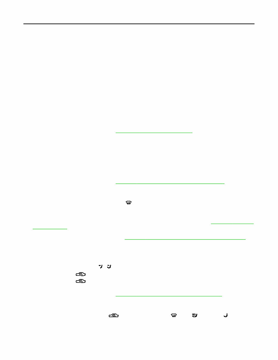
HAC-6 < BASIC INSPECTION > [AUTOMATIC AIR CONDITIONER] INSPECTION AND ADJUSTMENT 1. The REAR CTRL indicator must be off. Press each rear air con- trol (front) mode door switches and confirm the discharge air comes out relative to the icon on each switch and according to the air distribution table. Refer to HAC-16, " Discharge Air Flow (Rear) " . 2. Press the REAR CTRL switch (indicator on) from the rear air control (front). 3. Press each rear air control (rear) mode door switches and con- firm the discharge air comes out relative to the icon on each switch and according to the air distribution table. Refer to HAC- 16, " Discharge Air Flow (Rear) " . Air mix door position is checked in the next step. If NG, go to HAC-31, " Air Mix Door Motor (Driver) Component Func- tion Check " . If OK, continue with next check. CHECKING REAR TEMPERATURE DECREASE 1. Press the REAR CTRL switch (indicator off). 2. Rotate the rear air control (front) temperature control dial counterclockwise to maximum cold. 3. Check for cold air at appropriate discharge air outlets. 4. Press the REAR CTRL switch (indicator on) from the rear air control (front). 5. Rotate the rear air control (rear) temperature control dial counterclockwise to maximum cold. 6. Check for cold air at appropriate discharge air outlets. If NG, listen for sound of air mix door motor operation. If OK, go to trouble diagnosis procedure for HAC-31, " Air Mix Door Motor (Driver) Component Function Check " . If air mix door motor appears to be malfunctioning, go to HAC-59, " Air Mix Door Motor (Rear) Diagnosis Procedure " . If OK, continue with next check. CHECKING REAR TEMPERATURE INCREASE 1. Press the REAR CTRL switch (indicator off). 2. Rotate the rear air control (front) temperature control dial clockwise to maximum heat. 3. Check for hot air at appropriate discharge air outlets. 4. Press the REAR CTRL switch (indictor on) from the rear air control (front). 5. Rotate the rear air control (rear) temperature control dial clockwise to maximum heat. 6. Check for hot air at appropriate discharge air outlets. If NG, listen for sound of air mix door motor operation. If OK, go to trouble diagnosis procedure for HAC-31, " Air Mix Door Motor (Driver) Component Function Check " . If air mix door motor appears to be malfunctioning, go to HAC-59, " Air Mix Door Motor (Rear) Diagnosis Procedure " . If NG, go to trouble diagnosis procedure for HAC-115, " Component Function Check " . If all operational checks are OK (symptom cannot be duplicated), go to HAC-3, " How to Perform Trouble Diag- nosis For Quick And Accurate Repair " and perform tests as outlined. If symptom appears, refer to HAC-106, " Symptom Matrix Chart " and perform applicable trouble diagnosis procedures. WJIA0541E Revision: July 2010 2011 Armada
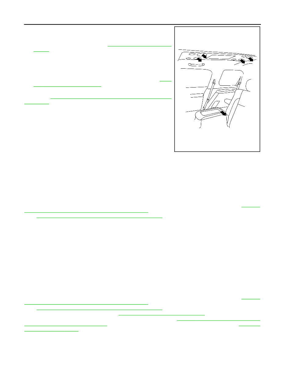
FUNCTION INFORMATION HAC-7 < SYSTEM DESCRIPTION > [AUTOMATIC AIR CONDITIONER] C D E F G H J K L M A B HAC N O P SYSTEM DESCRIPTION FUNCTION INFORMATION Component Part Location INFOID:0000000006145405 ENGINE COMPARTMENT AWIIA0274ZZ 1. Horn (view with grille removed) 2. Refrigerant pressure sensor E48 3. A/C compressor F3 4. Ambient sensor E1 (view with grille removed) 5. Water valve F68 Revision: July 2010 2011 Armada
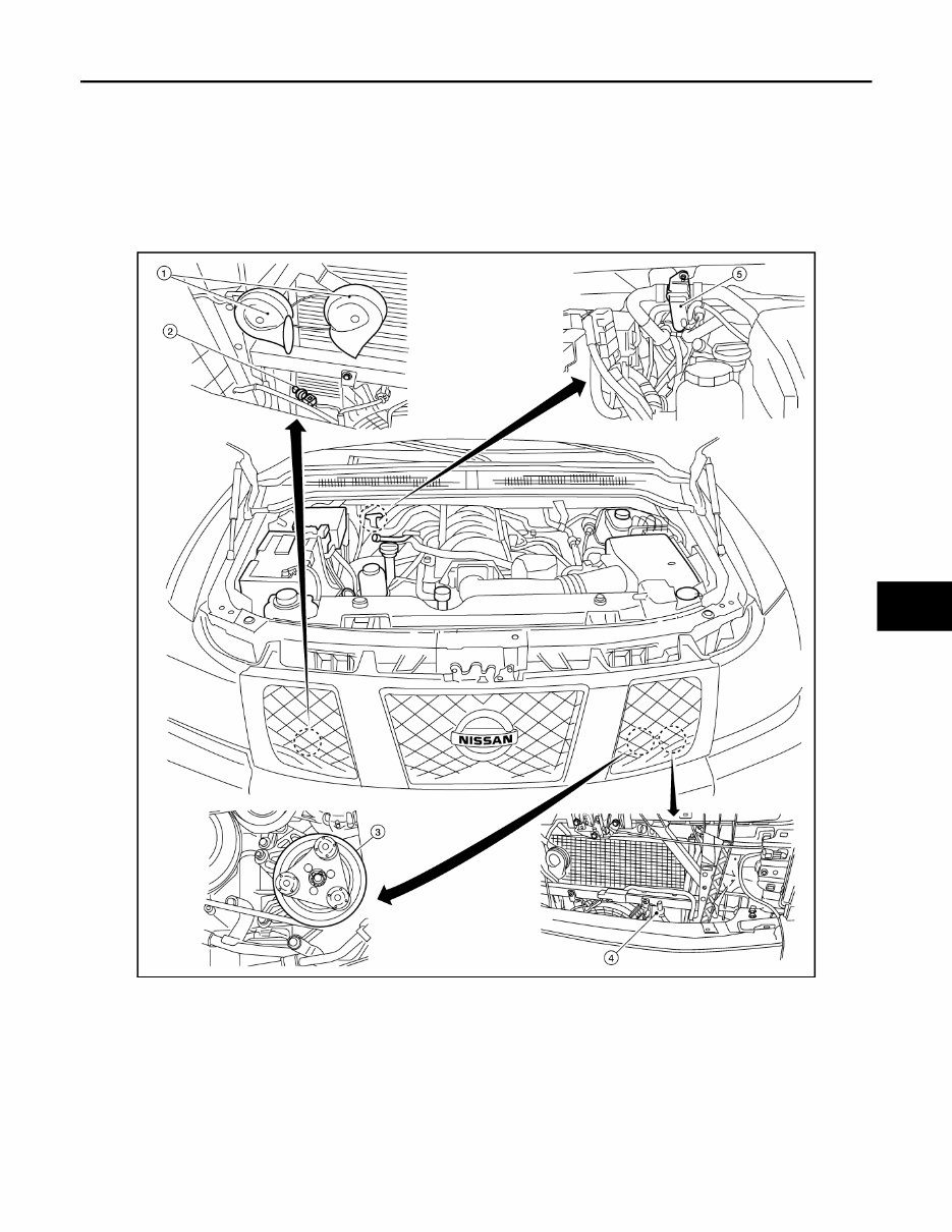
HAC-8 < SYSTEM DESCRIPTION > [AUTOMATIC AIR CONDITIONER] FUNCTION INFORMATION PASSENGER COMPARTMENT 1. A/C auto amp. M49, M50 2. In-vehicle sensor M32 3. Intake sensor M146 4. Intake door motor M58 5. Variable blower control (front) M122 6. Air mix door motor (passenger) M143 7. Mode door motor (front) M142 8. Defroster door motor M144 9. Air mix door motor (driver) M147 10. Optical sensor M302 ⇐ :Front AWIIA0079ZZ Revision: July 2010 2011 Armada
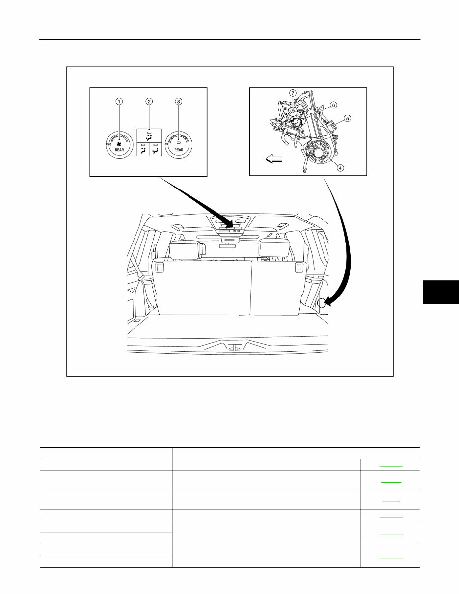
FUNCTION INFORMATION HAC-9 < SYSTEM DESCRIPTION > [AUTOMATIC AIR CONDITIONER] C D E F G H J K L M A B HAC N O P REAR PASSENGER COMPARTMENT Symptom Table INFOID:0000000006145406 1. Rear blower control (rear) 2. Rear mode switch (rear) 3. Rear temperature control (rear) 4. Rear blower motor B134 5. Variable blower control (rear) B133 6. Air mix door motor (rear) B155 7. Mode door motor (rear) B156 ⇐ : Front AWIIA0080ZZ Symptom Reference Page A/C system does not come on. Go to Trouble Diagnosis Procedure for A/C System. HAC-85 A/C system display is malfunctioning (with NAVI). Go to Navigation System. AV-324 A/C system display is malfunctioning (without NAVI). Go to Base Audio System. AV-31 A/C system cannot be controlled. Go to Self-diagnosis Function. HAC-23 Air outlet does not change. Go to Trouble Diagnosis Procedure for Mode Door Motor. HAC-26 Mode door motor is malfunctioning. Discharge air temperature does not change. Go to Trouble Diagnosis Procedure for Air Mix Door Motor. HAC-31 Air mix door motor is malfunctioning. Revision: July 2010 2011 Armada
HAC-10 < SYSTEM DESCRIPTION > [AUTOMATIC AIR CONDITIONER] FUNCTION INFORMATION Intake door does not change. Go to Trouble Diagnosis Procedure for Intake Door Motor. HAC-40 Intake door motor is malfunctioning. Defroster door motor is malfunctioning. Go to Trouble Diagnosis Procedure for Defroster Door Motor. HAC-43 Front blower motor operation is malfunction- ing. Go to Trouble Diagnosis Procedure for Front Blower Motor. HAC-48 Rear blower motor operation is malfunction- ing. Go to Trouble Diagnosis Procedure for Rear Blower Motor. HAC-53 Rear air discharge outlet does not change. Go to Trouble Diagnosis Procedure for Mode Door Motor (rear). HAC-58 Rear air temperature does not change. Go to Trouble Diagnosis Procedure for Air Mix Door Motor (rear). HAC-58 Magnet clutch does not engage. Go to Trouble Diagnosis Procedure for Magnet Clutch. HAC-67 Insufficient cooling Go to Trouble Diagnosis Procedure for Insufficient Cooling. HAC-107 Insufficient heating Go to Trouble Diagnosis Procedure for Insufficient Heating. HAC-115 Noise Go to Trouble Diagnosis Procedure for Noise. HAC-117 Self-diagnosis cannot be performed. Go to Trouble Diagnosis Procedure for Self-diagnosis. HAC-85 Memory function does not operate. Go to Trouble Diagnosis Procedure for Memory Function. HAC-119 Symptom Reference Page Revision: July 2010 2011 Armada
If you are in need of a repair manual for your 2011 Nissan Armada, look no further. Our accessible repair manual is the perfect resource for both professional mechanics and DIY enthusiasts. In the past, traditional paper repair manuals were the norm, but our digital format offers a more cost-effective and convenient alternative.
Whether you are tackling brake repairs, suspension component replacements, engine troubleshooting, or standard maintenance tasks, this repair manual has you covered. It provides comprehensive service information for the brakes, engine, suspension, steering, drivetrain, electrical systems, heating, air conditioning, and more.
By utilizing this 2011 Nissan Armada repair manual , you can save a significant amount of money on vehicle maintenance. Mechanics often charge high fees for their services, making a DIY approach a cost-effective solution. The is designed for easy use and is compatible with Windows, Mac computers, smartphones, and tablets.