ACC-1 ACCELERATOR CONTROL SYSTEM B ENGINE CONTENTS C D E F G H I J K L M SECTION ACC A ACC Revision: July 2007 2006 Armada PRECAUTIONS ......................................................... 2 Precautions for Supplemental Restraint System (SRS) “AIR BAG” and “SEAT BELT PRE-TEN- SIONER” ................................................................. 2 ACCELERATOR CONTROL SYSTEM ...................... 3 Removal and Installation ......................................... 3 REMOVAL ............................................................ 3 INSTALLATION .................................................... 4 INSPECTION AFTER INSTALLATION ................. 4 SERVICE DATA AND SPECIFICATIONS (SDS) ....... 5 Accelerator Control .................................................. 5 ADJUSTABLE ACCELERATOR PEDAL .............. 5
ACC-2 Revision: July 2007 PRECAUTIONS 2006 Armada PRECAUTIONS PFP:00001 Precautions for Supplemental Restraint System (SRS) “AIR BAG” and “SEAT BELT PRE-TENSIONER” EBS00QUP The Supplemental Restraint System such as “AIR BAG” and “SEAT BELT PRE-TENSIONER”, used along with a front seat belt, helps to reduce the risk or severity of injury to the driver and front passenger for certain types of collision. This system includes seat belt switch inputs and dual stage front air bag modules. The SRS system uses the seat belt switches to determine the front air bag deployment, and may only deploy one front air bag, depending on the severity of a collision and whether the front occupants are belted or unbelted. Information necessary to service the system safely is included in the SRS and SB section of this Service Man- ual. WARNING: ● To avoid rendering the SRS inoperative, which could increase the risk of personal injury or death in the event of a collision which would result in air bag inflation, all maintenance must be per- formed by an authorized NISSAN/INFINITI dealer. ● Improper maintenance, including incorrect removal and installation of the SRS, can lead to per- sonal injury caused by unintentional activation of the system. For removal of Spiral Cable and Air Bag Module, see the SRS section. ● Do not use electrical test equipment on any circuit related to the SRS unless instructed to in this Service Manual. SRS wiring harnesses can be identified by yellow and/or orange harnesses or harness connectors.
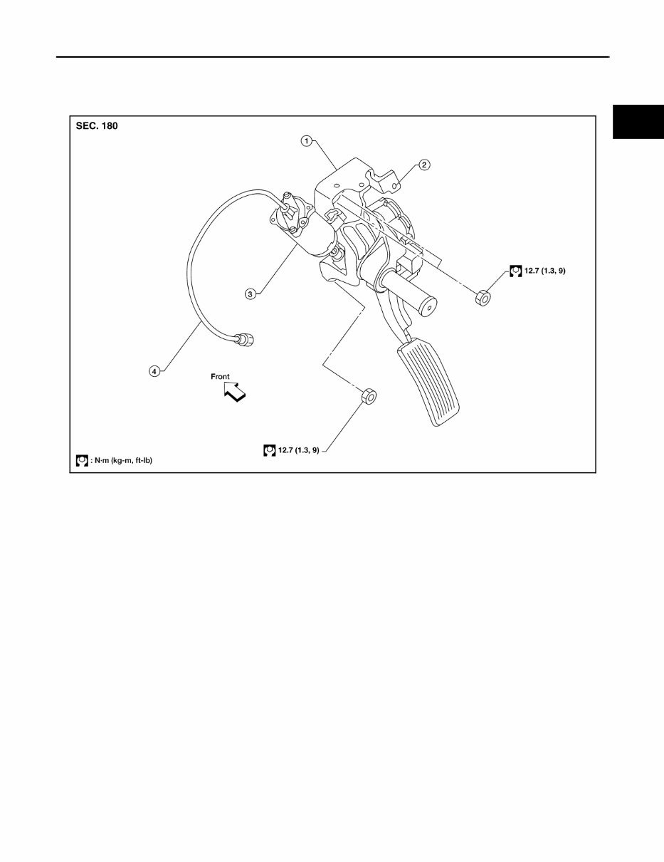
ACCELERATOR CONTROL SYSTEM ACC-3 C D E F G H I J K L M A ACC Revision: July 2007 2006 Armada ACCELERATOR CONTROL SYSTEM PFP:18005 Removal and Installation EBS00LLC Adjustable Accelerator Pedal CAUTION: ● Before removal and installation the accelerator and brake pedals must be in the frontmost posi- tion. This is to align the base position of the accelerator and brake pedals. ● Do not disassemble the accelerator pedal assembly. ● Do not remove the accelerator pedal position sensor from the accelerator pedal bracket. ● Do not disassemble the accelerator pedal adjusting mechanism. ● Avoid damage from dropping the accelerator pedal assembly during handling. ● Keep the accelerator pedal assembly away from water. REMOVAL 1. Move the accelerator and brake pedals to the frontmost position. 2. Turn the ignition switch OFF and disconnect the negative battery terminal. 3. Disconnect the adjustable brake pedal cable from the adjustable brake pedal. ● Unlock, then pull the adjustable brake pedal cable to disconnect it from the adjustable brake pedal. LBIA0379E 1. Adjustable accelerator pedal assem- bly 2. A/T control cable mounting bracket (part of the accelerator pedal assembly) 3. Adjustable pedal electric motor (part of the accelerator pedal assembly) 4. Adjustable brake pedal cable (part of the accelerator pedal assembly)
ACC-4 Revision: July 2007 ACCELERATOR CONTROL SYSTEM 2006 Armada 4. Disconnect the adjustable pedal electric motor electrical connec- tor. 5. Disconnect the adjustable pedal electric motor memory electri- cal connector, if equipped. 6. Disconnect the accelerator position sensor electrical connector. 7. Remove the two upper and one lower accelerator pedal nuts. 8. Remove the adjustable accelerator pedal assembly. CAUTION: ● Do not disassemble the accelerator pedal assembly. ● Do not remove the accelerator pedal position sensor from the accelerator pedal bracket. ● Do not disassemble the accelerator pedal adjusting mechanism. ● Avoid damage from dropping the accelerator pedal assembly during handling. ● Keep the accelerator pedal assembly away from water. INSTALLATION Installation is in the reverse order of removal. INSPECTION AFTER INSTALLATION ● Check that the accelerator pedal moves smoothly within the specified ranges. ● Depress and release the accelerator pedal to check that it returns smoothly to the original released posi- tion. ● Perform an electrical inspection of the accelerator pedal position sensor. Refer to EC-546, " DTC P2138 APP SENSOR " . CAUTION: When the harness connector of the accelerator pedal position sensor is disconnected, perform ″Accelerator Pedal Released Position Learning″. Refer to EC-78, " Accelerator Pedal Released Position Learning " . LBIA0380E Adjustable accelerator pedal – total pedal applied stroke : 48.3 mm (1.90 in) Adjustable accelerator pedal – total pedal adjustment travel : 73.2 mm (2.88 in)
SERVICE DATA AND SPECIFICATIONS (SDS) ACC-5 C D E F G H I J K L M A ACC Revision: July 2007 2006 Armada SERVICE DATA AND SPECIFICATIONS (SDS) PFP:00030 Accelerator Control EBS00LLD ADJUSTABLE ACCELERATOR PEDAL Unit: mm (in) Adjustable accelerator pedal - total pedal applied stroke 48.3 (1.90) Adjustable accelerator pedal - total pedal adjustment travel 73.2 (2.88)
The 2006 Nissan Armada Service & Repair Manual is a comprehensive repair guide that provides all the necessary troubleshooting and replacement procedures recommended by the manufacturer. With step-by-step instructions, clear images, and exploded-view illustrations, this manual makes it easy for car owners to fix problems on their own.
While the durability of the Nissan Armada is unquestionable, regular maintenance is still essential. And with time, certain parts may wear out and need to be replaced. This is where the repair manual comes in handy, providing all the necessary information to keep your vehicle in top shape.
The manual includes troubleshooting charts and replacement procedures recommended by the manufacturer, making it a valuable resource for any car owner. No need to flip through hundreds of pages to find specific information, as it is all easily accessible in this manual. Say goodbye to greasy, torn, or lost pages, as this digital manual can be carried around, searched, bookmarked, and even printed out for a physical copy.
The 2006 Nissan Armada Service & Repair Manual is compatible with various electronic devices, including PC and Mac computers, smartphones, and tablets. All you need is Adobe Reader, which is available for free. Whether you prefer a digital or physical copy, this repair manual is a must-have for every Nissan Armada owner to save on repairs, increase reliability, and keep your vehicle running smoothly for years to come.






 Lifetime Access




