Precaution for Supplemental Restraint System (SRS) "AIR BAG" and "SEAT BELT PRE-TENSIONER" The Supplemental Restraint System such as “AIR BAG” and “SEAT BELT PRE-TENSIONER”, used along with a front seat belt, helps to reduce the risk or severity of injury to the driver and front passenger for certain types of collision. Information necessary to service the system safely is included in the SR and SB section of this Service Manual. WARNING: To avoid rendering the SRS inoperative, which could increase the risk of personal injury or death in the event of a collision which would result in air bag inflation, all maintenance must be performed by an authorized NISSAN/INFINITI dealer. Improper maintenance, including incorrect removal and installation of the SRS, can lead to personal injury caused by unintentional activation of the system. For removal of Spiral Cable and Air Bag Module, see the SR section. Do not use electrical test equipment on any circuit related to the SRS unless instructed to in this Service Manual. SRS wiring harnesses can be identified by yellow and/or orange harnesses or harness connectors. PRECAUTIONS WHEN USING POWER TOOLS (AIR OR ELECTRIC) AND HAMMERS WARNING: When working near the Airbag Diagnosis Sensor Unit or other Airbag System sensors with the Ignition ON or engine running, DO NOT use air or electric power tools or strike near the sensor(s) with a hammer. Heavy vibration could activate the sensor(s) and deploy the air bag(s), possibly causing serious injury. When using air or electric power tools or hammers, always switch the Ignition OFF, disconnect the battery and wait at least 3 minutes before performing any service.
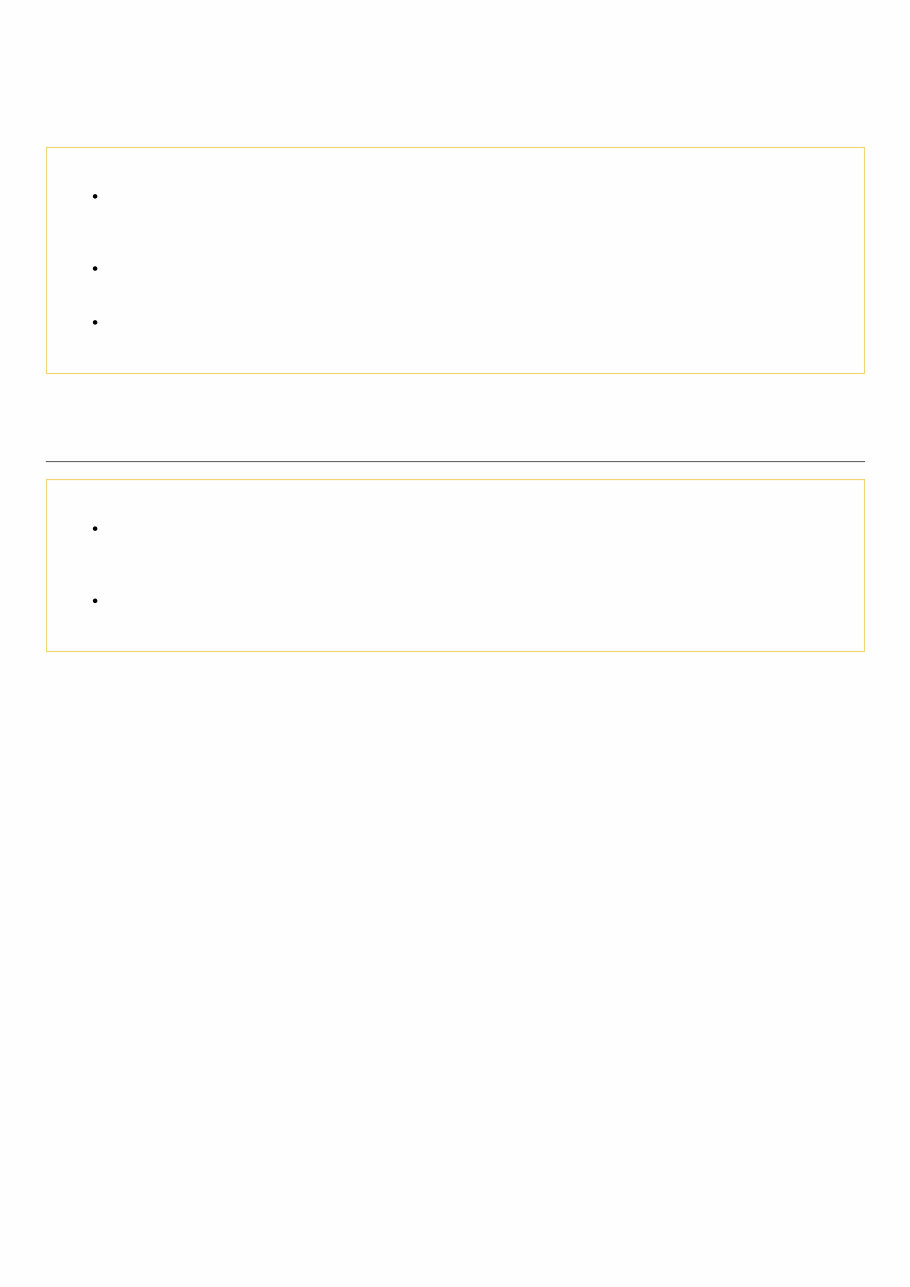
Precaution for Procedure without Cowl Top Cover When performing the procedure after removing cowl top cover, cover the lower end of windshield with urethane, etc. NISA0000000007988978-01-PIIB3706J
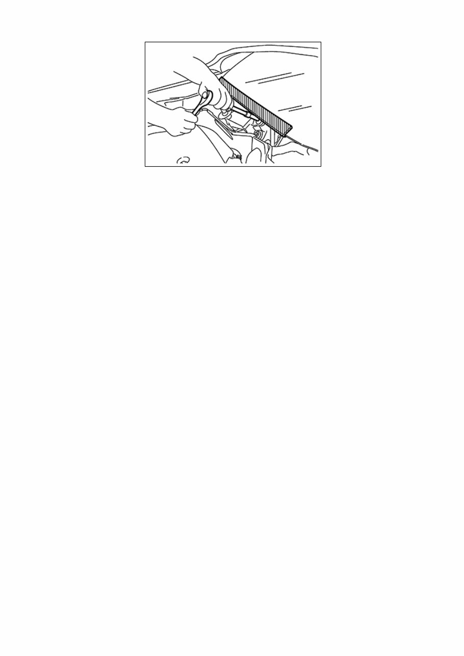
Precaution for Brake System WARNING: Clean any dust from the front brake and rear brake with a vacuum dust collector. Never blow with compressed air. CAUTION: Brake fluid use refer to Fluids and Lubricants. Do not reuse drained brake fluid. Do not spill or splash brake fluid on painted surfaces. Brake fluid may seriously damage paint. Wipe it off immediately and wash with water if it gets on a painted surface. Always clean with new brake fluid when cleaning the master cylinder, brake caliper and other components. Do not use mineral oils such as gasoline or light oil to clean. They may damage rubber parts and cause improper operation. Always loosen the brake tube flare nut with a flare nut wrench. Tighten the brake tube flare nut to the specified torque with crowfoot (A) and torque wrench (B). NISA0000000008599603-01-JPFIA0001ZZ Always confirm the specified tightening torque when installing the brake pipes. Turn the ignition switch OFF and disconnect the ABS actuator and electric unit (control unit) connector or the battery negative terminal before performing the work. Check that no brake fluid leakage is present after replacing the parts. Burnish the brake contact surfaces after refinishing or replacing rotors, after replacing pads, or if a soft pedal occurs at very low mileage. Front brake: refer to Brake Burnishing. Rear brake: refer to Brake Burnishing.
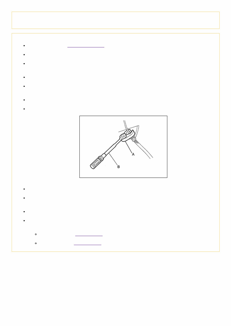
Special Service Tool The actual shape of the tools may differ from those illustrated here. Tool number (TechMate No.) Tool name Description ( — ) (J-46532) Brake and clutch pedal height measurement tool NISA0000000007988980-01- LFIA0227E Measuring brake pedal height 38-PFM90.5 ( — ) Pro-Cut PFM 90 On-Car Brake Lathe NISA0000000007988980-02- ALFIA0092ZZ Refinishing rotors
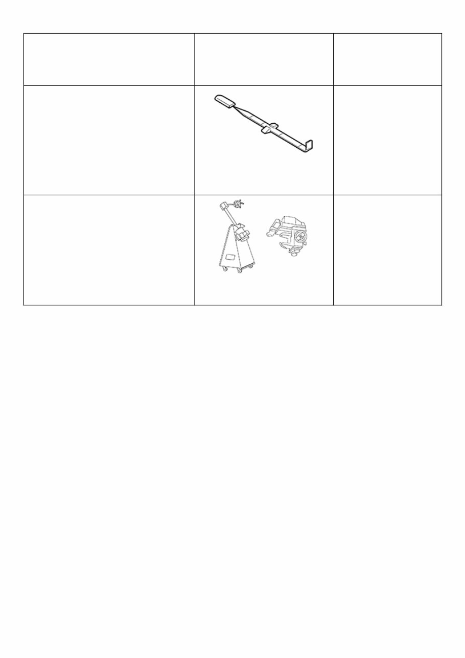
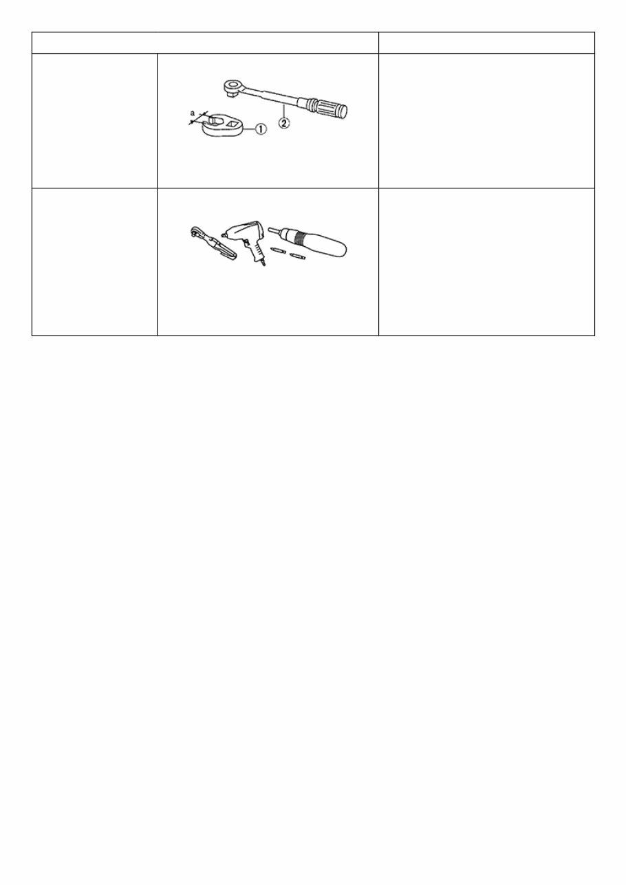
Commercial Service Tool Tool name Description 1. Flare nut crowfoot 2. Torque wrench NISA0000000007988981-01-NT360 Removing and installing brake piping a: 10mm (0.39 in)/12mm (0.47 in) Power tool NISA0000000007988981-02- PIIB1407E Loosening nuts, screws and bolts
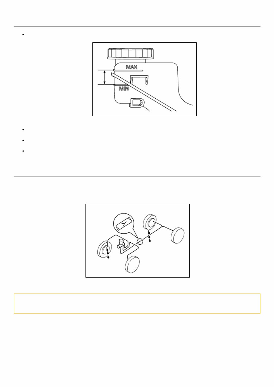
Inspection BRAKE FLUID LEVEL Make sure that the brake fluid level in the reservoir tank is between the MAX and MIN lines. NISA0000000008571547-01-ALFIA0273ZZ Visually check around the reservoir tank for brake fluid leakage. If the brake fluid level is excessively low, check the brake system for leakage. If brake warning lamp remains illuminated after parking brake pedal is released, check the brake system for brake fluid leakage. BRAKE LINE 1 Check brake line (tubes and hoses) for cracks, deterioration or other damage. Replace any damaged parts. 2 Check for brake fluid leakage by depressing brake pedal under a force of 785 N (80 kg-f, 177 lb-f) for approximately 5 seconds while engine is running. NISA0000000008571547-02-SBR389C CAUTION: If brake fluid leakage occurs around joints, retighten or replace damaged parts as necessary.
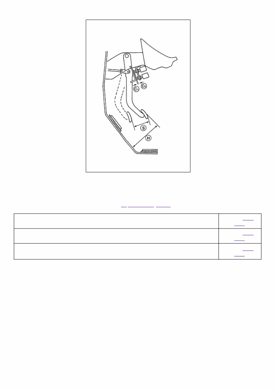
Inspection 1 Inspect the brake pedal height (H) from the floor using Tool at a 90° angle to the floor. NISA0000000008571543-01-AWFIA0913ZZ Tool number : — (J-46532) 2 Adjust the brake pedal height to specifications. Refer to Inspection and Adjustment. Brake Pedal Specifications Brake pedal height (H) (from dash lower panel top surface) Refer to Brake Pedal. Brake pedal full stroke (S) Refer to Brake Pedal. Clearance between stopper bracket (C 1 ) and threaded end of the stop lamp switch and ASCD cancel switch (C 2 ) Refer to Brake Pedal.
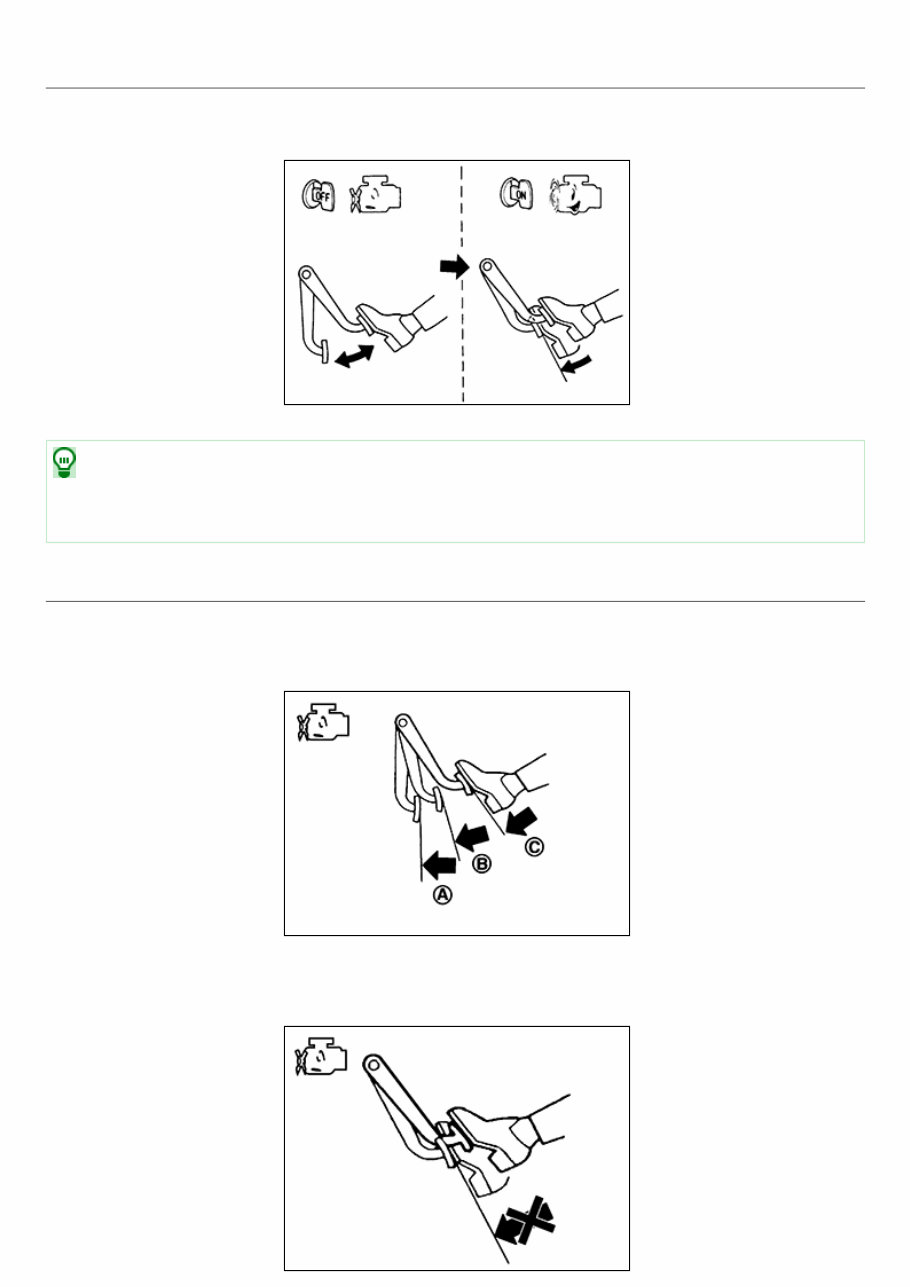
Inspection OPERATION Depress the brake pedal several times at five second intervals with the engine stopped. Start the engine with the brake pedal fully depressed. Check that the clearance between brake pedal and dash lower panel decreases. NISA0000000008571551-01-BRA0037D NOTE: A slight impact with a small click may be felt on the pedal when the brake pedal is fully depressed. This is normal brake system operation. VACUUM INSPECTION Idle the engine for one minute to apply vacuum to the brake booster. Stop the engine. Depress the brake pedal several times at five second intervals until the accumulated vacuum is released to atmospheric pressure. Check that the clearance between brake pedal and dash lower panel gradually increases (A → B → C) each time the brake pedal is depressed during this operation. NISA0000000008571551-02-JPFIA0043ZZ Depress the brake pedal with the engine running. Then stop the engine while holding down the brake pedal. Check that the brake pedal stroke does not change after holding down the brake pedal for 30 seconds or more.
NISA0000000008571551-03-JPFIA0044ZZ NOTE: A slight impact with a small click may be felt on the pedal when the brake pedal is fully depressed. This is normal brake system operation.
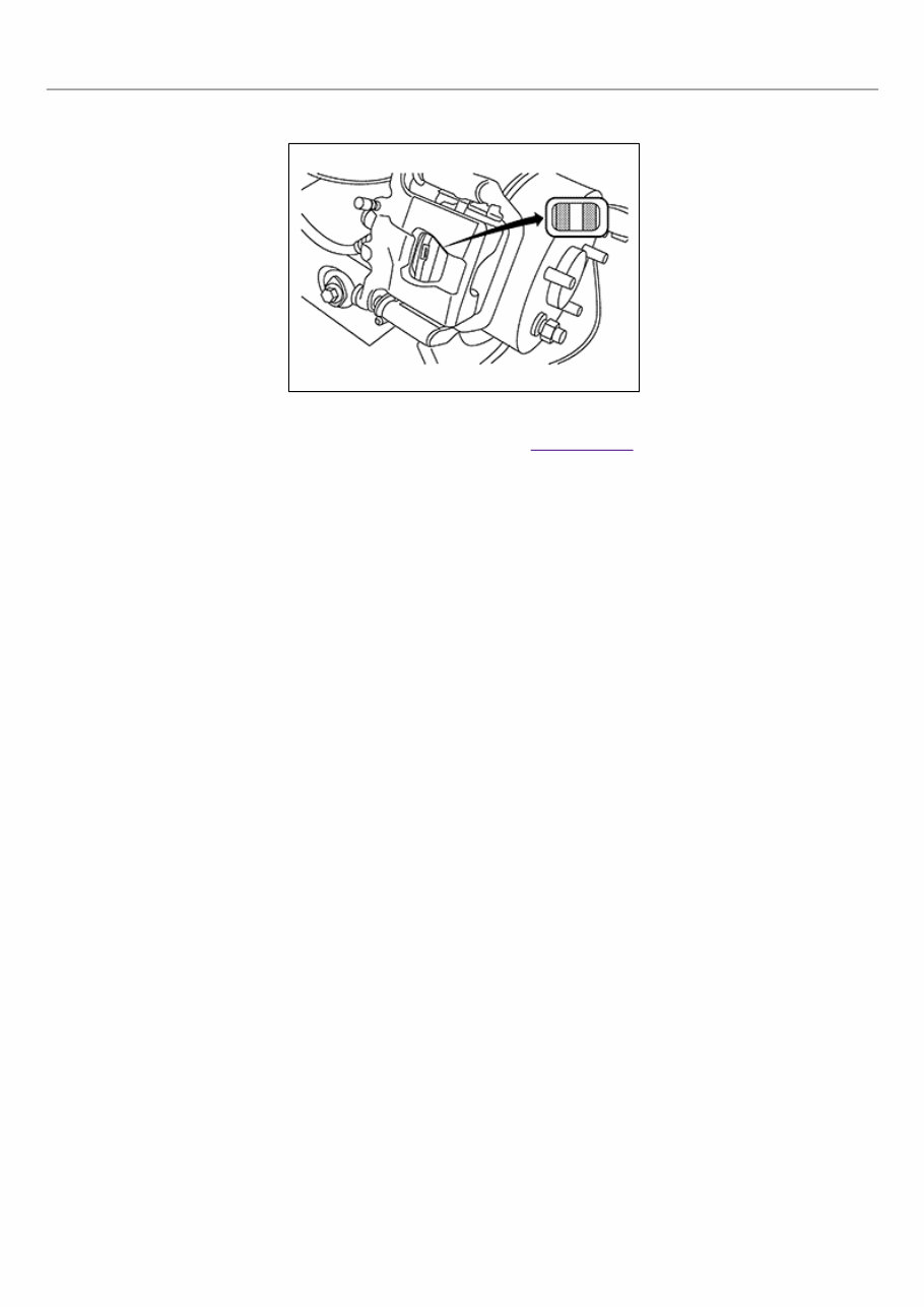
Inspection PAD WEAR Check pad thickness from an inspection hole on caliper body. Check using a scale if necessary. NISA0000000007988985-01-ALFIA0272ZZ Wear limit thickness : Refer to Rear Disc Brake.
The 2013 Nissan Altima OEM Service & Repair Manual gives you full dealer-grade procedures for maintaining and repairing both the 2.5L QR25DE I4 and the 3.5L VQ35DE V6 models. Whether you're working at a professional shop or just taking care of your own car at home, this manual lays out the steps clearly and without the extra fluff.
It covers engine service, transmission maintenance, cooling system repairs, suspension tuning, brake work, and troubleshooting for common drivability problems. Every procedure follows factory-approved methods, broken down into simple, step-by-step instructions that even first-timers can follow without feeling lost.
If you're planning to keep your Altima running smoothly for years — whether it's daily commutes, long trips, or just weekend errands — this service & repair manual puts the right technical info in your hands, exactly when you need it.
Printable: Yes Language: English Compatibility: Pretty much any electronic device, incl. PC & Mac computers, Android and Apple smartphones & tablet, etc. Requirements: Adobe Reader (free)