Revision History Revision History Date Revision Contents 2005.10.25 • Portions of “14.2 Diagnostic Trouble Code Datails" revised. (See P1-37, 38, 39, 40, 41) • "15.1 Engine ECU Externa Wring Diagram”illustration (Applicable Illust. code: Q001257E, Q001258E) replaced. (See P1-42, 43) • Portions of the "15.2 Engine ECU Connector Diagram” Terminal Connections (1), (2), (3) replaced . (See P1-43, 44, 45)
Table of Contents Operation Section 1. PRODUCT APPILCATION INFOR- MATION 1.1 Application .................................................. 1-1 1.2 System Components Part Number ............. 1-1 2. OUTLINE OF SYSTEM 2.1 Common Rail System Characteristics ........ 1-2 2.2 Features of Injection Control ....................... 1-2 2.3 Comparison to the Conventional System.... 1-3 2.4 Composition ................................................ 1-3 2.5 Operation .................................................... 1-4 2.6 Fuel System ................................................ 1-4 2.7 Control System ........................................... 1-4 3. SUPPLY PUMP 3.1 Outline......................................................... 1-6 3.2 Exterior View Diagram ................................ 1-7 3.3 Supply Pump Internal Fuel Flow ................. 1-7 3.4 Construction of Supply Pump ..................... 1-8 3.5 Operation of the Supply Pump .................... 1-9 4. SUPPLY PUMP COMPONENT PARTS 4.1 Feed Pump ................................................1-11 4.2 SCV ( Suction Control Valve ) ....................1-11 4.3 Fuel Temperature Sensor ......................... 1-13 5. RAIL 5.1 Outline....................................................... 1-14 6. RAIL COMPONENTS PARTS 6.1 Rail Pressure Sensor (Pc Sensor) ............ 1-15 6.2 Pressure limiter ......................................... 1-15 7. INJECTOR (G2 TYPE) 7.1 Outline....................................................... 1-16 7.2 Characteristics .......................................... 1-16 7.3 Exterior View Diagram .............................. 1-17 7.4 Construction .............................................. 1-18 7.5 Operation .................................................. 1-18 7.6 QR Codes ................................................. 1-19 7.7 Injector Actuation Circuit ........................... 1-21 8. OPERATION OF CONTROL SYS- TEM COMPONENTS 8.1 Engine Control System Diagram............... 1-22 8.2 Engine ECU (Electronic Control Unit) ....... 1-22 8.3 Cylinder Recognition Sensor (TDC) .......... 1-23 8.4 Turbo Pressure Sensor ............................. 1-23 8.5 Mass Air Flow Sensor ............................... 1-24 8.6 Electronic Control Throttle ........................ 1-25 9. VARIOUS TYPES OF CONTROL 9.1 Outline....................................................... 1-27 9.2 Fuel Injection Rate Control Function......... 1-27 9.3 Fuel Injection Quantity Control Function ... 1-27 9.4 Fuel Injection Timing Control Function...... 1-27 9.5 Fuel Injection Pressure Control Function (Rail Pressure Control Function) ............. 1-27 10. FUEL INJECTION QUANTITY CONTROL 10.1 Outline....................................................... 1-28 10.2 Injection Quantity Calculation Method ...... 1-28 10.3 Set Injection Quantities ............................. 1-28
Table of Contents 11. FUEL INJECTION TIMING CON- TROL 11.1 Ouline........................................................ 1-32 11.2 Main and Pilot Injection Timing Control..... 1-32 11.3 Microinjection Quantity Learning Control .. 1-33 12. FUEL INJECTION RATE CON- TROL 12.1 Outline....................................................... 1-35 13. FUEL INJECTION PRESSURE CONTROL 13.1 Fuel Injection Pressure ............................. 1-36 14. DIAGNOSTIC TROUBLE CODES (DTC) 14.1 About the Codes Shown in the Table ........ 1-37 14.2 Diagnostic Trouble Code Details............... 1-37 15. EXTERNAL WIRING DIAGRAM 15.1 Engine ECU External Wiring Diagram ...... 1-42 15.2 Engine ECU Connector Diagram .............. 1-43
Operation Section 1 – 1 1. PRODUCT APPILCATION INFORMATION 1.1 Application 1.2 System Components Part Number Vehicle Manufac- ture Vehicle Name Engine Model Specification Destination (Vol- ume) Line Off Period MITSUBISHI TRITON 4D56 2WD (MT/AT) Thailand June, 2005 4WD (MT) 4M41 4WD (MT/AT) Parts Name DENSO P/N Manufacturer P/N Remarks Supply pump SM294000-0331 1460A001 For 4D56 Engine Model SM294000-0341 1460A003 For 4M41 Engine Model Injector SM095000-5600 1465A041 For 4D56 Engine Model SM095000-5760 1465A054 For 4M41 Engine Model Rail SM095440-0640 1465A034 ALL Engine ECU MA275800-425# 1860A392 For 4D56 Engine Model (4WD) MA275800-431# 1860A523 For 4D56 Engine Model (2WD MT) MA275800-432# 1860A524 For 4D56 Engine Model (2WD AT) MA275800-357# 1860A390 For 4M41 Engine Model (4WD) Turbo pressure sensor 079800-5960 MR577031 ALL Cylinder recognition sensor (TDC) 949979-1590 1865A074 For 4M41 Engine Model Electronic control throttle 197920-0020 1450A033 For 4M41, 4D56 Engine Model (4WD) Fuel temperature sensor 179730-0020 MR547077 ALL Mass air flow meter VN197400-4030 1460A001 ALL
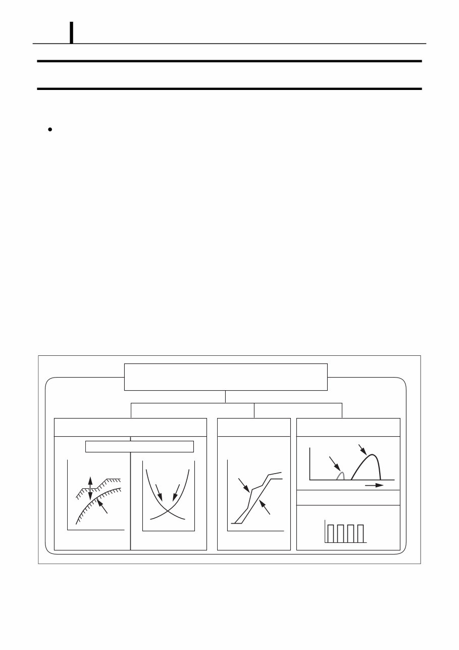
Operation Section 1 – 2 2. OUTLINE OF SYSTEM 2.1 Common Rail System Characteristics The common rail system uses a type of accumulation chamber called a rail to store pressurized fuel, and injectors that contain elec- tronically controlled solenoid valves to inject the pressurized fuel into the cylinders. Because the engine ECU controls the injection system (injection pressure, injection rate, and injection timing), the injection system is independent, and thus unaffected by the engine speed or load. This ensures a stable injection pressure at all times, particularly in the low engine speed range, and dramatically de- creases the amount of black smoke ordinarily emitted by a diesel engine during start-up and acceleration. As a result, exhaust gas emis- sions are cleaner and reduced, and higher power output is achieved. 2.2 Features of Injection Control (1) Injection Pressure Control • Enables high-pressure injection even at low engine speeds. • Optimizes control to minimize particulate matter and NOx emissions. (2) Injection Timing Control • Enables finely tuned optimized control in accordance with driving conditions. (3) Injection Rate Control • Pilot injection control injects a small amount of fuel before the main injection. Q001223E Common Rail System Injection Pressure Control Injection Timing Control Injection Rate Control Optimization, High Pressurization Common Rail System Conventional Pump Conventional Pump Speed Speed Injection Pressure Optimization Common Rail System Particulate NOx Injection Timing Speed Injection Quantity Control Cylinder Injection Quantity Correction Pre-Injection Main Injection Crankshaft Angle Injection Rate Injection Pressure 1 3 4 2
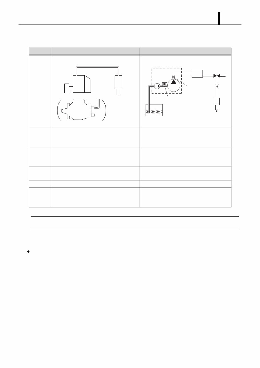
Operation Section 1 – 3 2.3 Comparison to the Conventional System < NOTE > *1 : TWV: Two Way Valve *2 : SCV: Suction Control Valve 2.4 Composition The common rail system consists primarily of a supply pump, rail, injectors, and engine ECU. In-line, VE Pump Common Rail System System Injection Quantity Control Pump (Governor) Engine ECU, Injector (TWV) *1 Injection Timing Control Pump (Timer) Engine ECU, Injector (TWV) *1 Rising Pressure Pump Engine ECU, Supply Pump Distributor Pump Engine ECU, Rail Injection Pressure Control Dependent upon Speed and Injection Quantity Engine ECU, Supply Pump (SCV) *2 Q001224E High-pressure Pipe Momentary High Pressure Nozzle Governor Timer In-line Pump VE Pump Q001225E Rail Usually High Pressure Supply Pump Injector Feed Pump SCV (Suction Control Valve) Delivery Valve Fuel Tank
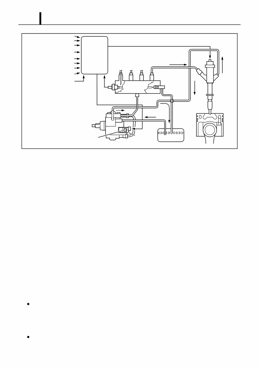
Operation Section 1 – 4 2.5 Operation (1) Supply Pump (HP3) • The supply pump draws fuel from the fuel tank, and pumps the high pressure fuel to the rail. The quantity of fuel discharged from the supply pump controls the pressure in the rail. The SCV (Suction Control Valve) in the supply pump effects this control in accordance with commands received from the engine ECU. (2) Rail • The rail is mounted between the supply pump and the injector, and stores the high-pressure fuel. (3) Injector (G2 type) • This injector replaces the conventional injection nozzle, and achieves optimal injection by effecting control in accordance with signals from the engine ECU. Signals from the engine ECU determine the duration and timing in which current is applied the injector. This in turn, determines the quantity, rate and timing of the fuel that is injected from the injector. (4) Engine ECU • The engine ECU calculates data received from the sensors to comprehensively control the injection quantity, timing and pressure, as well as the EGR (exhaust gas recirculation). 2.6 Fuel System This system comprises the route through which diesel fuel flows from the fuel tank via the rail to the supply pump, and is injected through the injector, as well as the route through which the fuel returns to the tank via the overflow pipe. 2.7 Control System In this system, the engine ECU controls the fuel injection system in accordance with signals received from various sensors. The com- ponents of this system can be broadly divided into the following three types: (1) sensors; (2) ECU; and (3) actuators. Fuel Temperature Accelerator Opening Turbo Pressure, Atmospheric Air Pressure Intake Airflow Rate Rail Pressure Sensor Rail Engine ECU Fuel Temperature Sensor Supply Pump Fuel Tank Injector Pressure Limiter SCV (Suction Control Valve) Intake Air Temperature Coolant Temperature Crankshaft position Cylinder Recognition Position Q001226E Engine Speed
Operation Section 1 – 5 (1) Sensors • Detect the engine and driving conditions, and convert them into electrical signals. (2) Engine ECU • Performs calculations based on the electrical signals received from the sensors, and sends them to the actuators in order to achieve optimal conditions. (3) Actuators • Operate in accordance with electrical signals received from the ECU. Injection system control is undertaken by electronically control- ling the actuators. The injection quantity and timing are determined by controlling the duration and timing in which current is applied to the TWV (Two-Way Valve) in the injector. Injection pressure is determined by controlling the SCV (Suction Control Valve) in the supply pump. Q001227E Crankshaft Position Sensor (NE) Accelerator Position Sensor Engine Speed Cylider Recognition Sensor (TDC) Cylinder Recognition Load Injector Supply Pump (SCV) •Injection Quantity Control •Injection Timing Control •Fuel Pressure Control Other Sensors and Switches EGR, Air Intake Control Relay, Light Sensor Actuator Engine ECU
The Mitsubishi 4D56, 4M41 Common Rail Diesel Fuel System Manual is a technical guide dedicated to the DENSO common rail injection system used in Mitsubishi's turbo diesel engines from the mid-2000s to early 2010s. This manual is intended for advanced technicians and experienced diesel mechanics needing detailed reference material specific to fuel delivery, injection timing, and diagnostic routines.
It provides full coverage of fuel system components including supply pumps, injectors, sensors, and engine control modules, as well as diagnostic flowcharts and ECU input/output checks. This manual is essential for troubleshooting hard-start conditions, poor fuel economy, misfires, or injector performance issues in vehicles equipped with 4D56 or 4M41 engines.
Manual Coverage:
System Overview and Operating Principles
Internal Structure and Component Specifications
DENSO HP3 High-Pressure Supply Pump
Common Rail Fuel System and G2-Type Injectors
Suction Control Valve (SCV) Inspection and Calibration
Fuel System Schematics and Flow Logic
Fuel Rail Pressure Sensor and Regulator Functions
Pressure Regulation and Feedback Control Systems
Injector Return Flow and Leak Testing
Fuel Line Removal, Torque Specs, and Reinstallation
Priming Procedures and Fuel Bleeding Techniques
ECU Input/Output Signal Logic for Fuel Management
Diagnostic Routines and Scan Tool Parameters
Wiring Diagrams for Injectors, ECU, and Fuel Sensors
This manual is a valuable asset for in-depth troubleshooting and repair of the Mitsubishi common rail diesel injection system — particularly for workshop technicians and diesel performance specialists.
Printable: Yes Language: English Compatibility: Windows, macOS, Linux Requirements: PDF reader software
Recently Viewed
5,521,897Happy Clients
2,594,462eManuals
1,120,453Trusted Sellers
15Years in Business
Price:
Actual Price:
2008-2013 Mitsubishi Triton L200 Service & Repair Manual